Tool/software: Code Composer Studio
I am tasked with reading an AD4001 ADC (Analog Devices) at 4kHz. I appear to be reading data from the ADC but it is not reliable. Does anyone have experience with this device?
I have the TM4C123G Launchpad connected to the ADC:
SSIOTX is NC
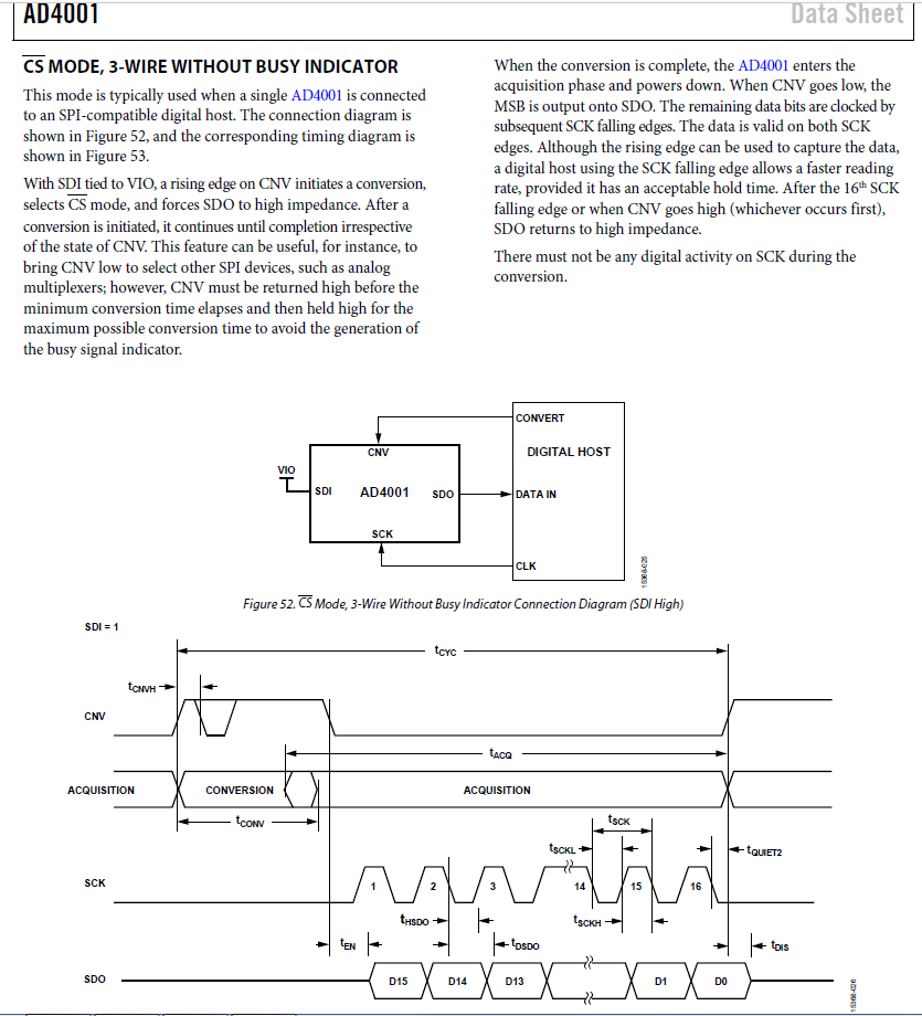
SSIORX is connected to the SDO pin
SSIOCLK is connected to the SCK clock pin.
I am using a GPIO to control the CNV pin.
SDI on the ADC is pulled high to VIO.
I'm looking at the SPI on the scope and it looks like on some occasions, there is data on the line before the clock starts?
Here is the code snippets:
(INITIALIZATION)
void SpiInit_SSI0(void) {
// The SSI0 peripheral must be enabled for use.
SysCtlPeripheralEnable(SYSCTL_PERIPH_SSI0);
// For the TM4C123G, SSI0 is used with PortA[5:2].
SysCtlPeripheralEnable(SYSCTL_PERIPH_GPIOA);
// Configure the pin muxing for SSI0 functions on port A2, A3, A4, and A5.
GPIOPinConfigure(GPIO_PA2_SSI0CLK); // Configure PA2 for the clock
// GPIOPinConfigure(GPIO_PA3_SSI0FSS); // Use a GPIO for the *CS function.
GPIOPinConfigure(GPIO_PA4_SSI0RX); // Configure PA4 for the Master Receive
GPIOPinConfigure(GPIO_PA5_SSI0TX); // Configure PA5 for the Master Transmit
GPIOPinTypeGPIOOutput(GPIO_PORTA_BASE, GPIO_PIN_3); // Configure PA3 as a GPIO for *CS
// Configure the GPIO settings for the SSI pins. This function also gives
// control of these pins to the SSI hardware. Consult the data sheet to
// see which functions are allocated per pin.
// The pins are assigned as follows:
// PA5 - SSI0Tx
// PA4 - SSI0Rx
// PA3 - SSI0Fss - Not Used
// PA2 - SSI0CLK
GPIOPinTypeSSI(GPIO_PORTA_BASE, GPIO_PIN_5 | GPIO_PIN_4 | GPIO_PIN_2);
GPIOPinWrite(GPIO_PORTA_BASE, GPIO_PIN_3, 0); // Enable the GPIO pin for *CS
// Configure and enable the SSI port for SPI master mode. Use SSI0,
// system clock supply, idle clock level low and active low clock in
// freescale SPI mode, master mode, 1MHz SSI frequency, and 8-bit data.
// For SPI mode, you can set the polarity of the SSI clock when the SSI
// unit is idle. You can also configure what clock edge you want to
// capture data on. Please reference the datasheet for more information on
// the different SPI modes.
SSIConfigSetExpClk(SSI0_BASE, 80000000, SSI_FRF_MOTO_MODE_0,
SSI_MODE_MASTER, 20000000, 16);
// Enable the SSI0 module.
SSIEnable(SSI0_BASE);
uint32_t pui32DataRx[2];
// Read any present data from the SSI port. This makes sure the receive
// FIFOs are empty, so we don't read any unwanted junk. This is done here
// because the SPI SSI mode is full-duplex, which allows you to send and
// receive at the same time. The SSIDataGetNonBlocking function returns
// "true" when data was returned, and "false" when no data was returned.
// The "non-blocking" function checks if there is any data in the receive
// FIFO and does not "hang" if there isn't.
while(SSIDataGetNonBlocking(SSI0_BASE, &pui32DataRx[0])){ }
}
GPIO_PORTA_DATA_R |= 0xFF;
SysCtlDelay(4);
GPIO_PORTA_DATA_R &= 0xF7;
SSIDataPut(argSsiBase, 0x1400); //0x1406); //pui32DataTx[ui32Index]);
// Wait until SSI0 is done transferring all the data in the transmit FIFO.
// while(SSIBusy(argSsiBase)){}
uint32_t data = 0xCCCCCCCC;
SSIDataGet(argSsiBase, &data);
// while(SSIBusy(argSsiBase)){}
return convertToVoltage((int16_t)(data & 0xFFFF));