Part Number: EK-TM4C1294XL
Hi all,
I have been developing an application where TIVA board will send a command to other Microcontroller(STM32F4) over SPI. Upon receiving the command STM32F4 Will send processed data back to TIVA board over SPI. (Here TIVA board is SPI master and STM32F4 is slave).
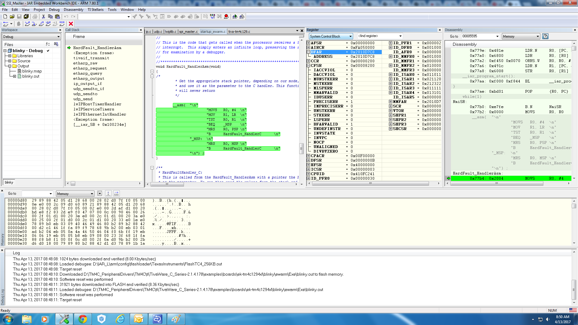
This received data by TIVA board will be sent to the PC over Ethernet. I've developed these applications individually but when i try to merge the two codes, the merged code after sometime jumps to Fault ISR. I don't understand what exactly is happening and why the code is jumping to fault ISR.
Help would be really appreciated.
I'm Posting the code below. Please refer it. and i'll post the Fault address as well.(Note: I'm using IAR as my toolchain).
//*****************************************************************************
//
// spi_master.c - Example demonstrating how to configure SSI0 in SPI master
//                mode.
//
// Copyright (c) 2010-2017 Texas Instruments Incorporated.  All rights reserved.
// Software License Agreement
//
//   Redistribution and use in source and binary forms, with or without
//   modification, are permitted provided that the following conditions
//   are met:
//
//   Redistributions of source code must retain the above copyright
//   notice, this list of conditions and the following disclaimer.
//
//   Redistributions in binary form must reproduce the above copyright
//   notice, this list of conditions and the following disclaimer in the
//   documentation and/or other materials provided with the
//   distribution.
//
//   Neither the name of Texas Instruments Incorporated nor the names of
//   its contributors may be used to endorse or promote products derived
//   from this software without specific prior written permission.
//
// THIS SOFTWARE IS PROVIDED BY THE COPYRIGHT HOLDERS AND CONTRIBUTORS
// "AS IS" AND ANY EXPRESS OR IMPLIED WARRANTIES, INCLUDING, BUT NOT
// LIMITED TO, THE IMPLIED WARRANTIES OF MERCHANTABILITY AND FITNESS FOR
// A PARTICULAR PURPOSE ARE DISCLAIMED. IN NO EVENT SHALL THE COPYRIGHT
// OWNER OR CONTRIBUTORS BE LIABLE FOR ANY DIRECT, INDIRECT, INCIDENTAL,
// SPECIAL, EXEMPLARY, OR CONSEQUENTIAL DAMAGES (INCLUDING, BUT NOT
// LIMITED TO, PROCUREMENT OF SUBSTITUTE GOODS OR SERVICES; LOSS OF USE,
// DATA, OR PROFITS; OR BUSINESS INTERRUPTION) HOWEVER CAUSED AND ON ANY
// THEORY OF LIABILITY, WHETHER IN CONTRACT, STRICT LIABILITY, OR TORT
// (INCLUDING NEGLIGENCE OR OTHERWISE) ARISING IN ANY WAY OUT OF THE USE
// OF THIS SOFTWARE, EVEN IF ADVISED OF THE POSSIBILITY OF SUCH DAMAGE.
//
// This is part of revision 2.1.4.178 of the Tiva Firmware Development Package.
//
//*****************************************************************************

#include <stdbool.h>
#include <stdint.h>
#include "inc/hw_ints.h"
#include "inc/hw_memmap.h"
#include "driverlib/flash.h"
#include "driverlib/interrupt.h"
#include "driverlib/gpio.h"
#include "driverlib/pin_map.h"
#include "driverlib/ssi.h"
#include "driverlib/sysctl.h"
#include "driverlib/systick.h"
#include "utils/locator.h"
#include "utils/lwiplib.h"
#include "utils/ustdlib.h"
#include "driverlib/uart.h"
#include "utils/uartstdio.h"
#include "driverlib/rom.h"
#include "driverlib/rom_map.h"
#include "driverlib/pinout.h"
//*****************************************************************************
//
//! \addtogroup ssi_examples_list
//! <h1>SPI Master (spi_master)</h1>
//!
//! This example shows how to configure the SSI0 as SPI Master.  The code will
//! send three characters on the master Tx then polls the receive FIFO until
//! 3 characters are received on the master Rx.
//!
//! This example uses the following peripherals and I/O signals.  You must
//! review these and change as needed for your own board:
//! - SSI0 peripheral
//! - GPIO Port A peripheral (for SSI0 pins)
//! - SSI0Clk - PA2
//! - SSI0Fss - PA3
//! - SSI0Rx  - PA4
//! - SSI0Tx  - PA5
//!
//! The following UART signals are configured only for displaying console
//! messages for this example.  These are not required for operation of SSI0.
//! - UART0 peripheral
//! - GPIO Port A peripheral (for UART0 pins)
//! - UART0RX - PA0
//! - UART0TX - PA1
//!
//! This example uses the following interrupt handlers.  To use this example
//! in your own application you must add these interrupt handlers to your
//! vector table.
//! - None.
//
//*****************************************************************************

//*****************************************************************************
//
// Defines for setting up the system clock.
//
//*****************************************************************************
#define SYSTICKHZ               500
#define SYSTICKMS               (1000 / SYSTICKHZ)

//*****************************************************************************
//
// Interrupt priority definitions.  The top 3 bits of these values are
// significant with lower values indicating higher priority interrupts.
//
//*****************************************************************************
#define SYSTICK_INT_PRIORITY    0x80
#define ETHERNET_INT_PRIORITY   0xC0

uint16_t port = 12;
uint8_t  ui8_Flag = 0;
struct udp_pcb *udp_1;
struct pbuf *pbuf1;

//*****************************************************************************
//
// The current IP address.
//
//*****************************************************************************
uint32_t g_ui32IPAddress;

//*****************************************************************************
//
// Number of bytes to send and receive.
//
//*****************************************************************************
#define NUM_SSI_DATA            3
uint32_t g_ui32SysClock;
uint32_t dummy = 0;
uint32_t pui32DataTx[3];
uint32_t pui32DataRx[16];

void
DisplayIPAddress(uint32_t ui32Addr)
{
    char pcBuf[16];

    //
    // Convert the IP Address into a string.
    //
    usprintf(pcBuf, "%d.%d.%d.%d", ui32Addr & 0xff, (ui32Addr >> 8) & 0xff,
            (ui32Addr >> 16) & 0xff, (ui32Addr >> 24) & 0xff);

    //
    // Display the string.
    //
    UARTprintf(pcBuf);
}

void
lwIPHostTimerHandler(void)
{
    uint32_t ui32NewIPAddress;

    //
    // Get the current IP address.
    //
    ui32NewIPAddress = lwIPLocalIPAddrGet();

    //
    // See if the IP address has changed.
    //
    if(ui32NewIPAddress != g_ui32IPAddress)
    {
        //
        // See if there is an IP address assigned.
        //
        if(ui32NewIPAddress == 0xffffffff)
        {
            //
            // Indicate that there is no link.
            //
            UARTprintf("Waiting for link.\n");
        }
        else if(ui32NewIPAddress == 0)
        {
            //
            // There is no IP address, so indicate that the DHCP process is
            // running.
            //
            UARTprintf("Waiting for IP address.\n");
        }
        else
        {
            //
            // Display the new IP address.
            //
            UARTprintf("IP Address: ");
            DisplayIPAddress(ui32NewIPAddress);
            UARTprintf("\nOpen a browser and enter the IP address.\n");
        }

        //
        // Save the new IP address.
        //
        g_ui32IPAddress = ui32NewIPAddress;
    }

    //
    // If there is not an IP address.
    //
    if((ui32NewIPAddress == 0) || (ui32NewIPAddress == 0xffffffff))
    {
        //
        // Do nothing and keep waiting.
        //
    }

    else
    {
      UARTprintf("I Have an IP");
      pbuf1 = pbuf_alloc(PBUF_TRANSPORT, 100, PBUF_RAM);
      pbuf1->payload = (void*) pui32DataRx;
      pbuf1->tot_len = 16;
      pbuf1->len = 16;
      udp_send(udp_1, pbuf1);
      pbuf_free(pbuf1);
    }

    ui8_Flag = 1;
}

//*****************************************************************************
//
// This function sets up UART0 to be used for a console to display information
// as the example is running.
//
//*****************************************************************************
void
InitConsole(void)
{

    //
    // Enable GPIO port A which is used for UART0 pins.
    // TODO: change this to whichever GPIO port you are using.
    //
    SysCtlPeripheralEnable(SYSCTL_PERIPH_GPIOA);

    //
    // Configure the pin muxing for UART0 functions on port A0 and A1.
    // This step is not necessary if your part does not support pin muxing.
    // TODO: change this to select the port/pin you are using.
    //
    GPIOPinConfigure(GPIO_PA0_U0RX);
    GPIOPinConfigure(GPIO_PA1_U0TX);

    //
    // Enable UART0 so that we can configure the clock.
    //
    SysCtlPeripheralEnable(SYSCTL_PERIPH_UART0);

    //
    // Use the internal 16MHz oscillator as the UART clock source.
    //
    UARTClockSourceSet(UART0_BASE, UART_CLOCK_PIOSC);

    //
    // Select the alternate (UART) function for these pins.
    // TODO: change this to select the port/pin you are using.
    //
    GPIOPinTypeUART(GPIO_PORTA_BASE, GPIO_PIN_0 | GPIO_PIN_1);

    //
    // Initialize the UART for console I/O.
    //
    UARTStdioConfig(0, 115200, 16000000);
}

void
SysTickIntHandler(void)
{
    //
    // Call the lwIP timer handler.
    //
    lwIPTimer(SYSTICKMS);


}

//*****************************************************************************
//
// Configure SSI0 in master Freescale (SPI) mode.  This example will send out
// 3 bytes of data, then wait for 3 bytes of data to come in.  This will all be
// done using the polling method.
//
//*****************************************************************************
int
main(void)
{
    uint32_t ui32Index;


    uint32_t ui32User0, ui32User1;
    uint8_t pui8MACArray[8];
    struct ip_addr ip_remote;
    //
    // Make sure the main oscillator is enabled because this is required by
    // the PHY.  The system must have a 25MHz crystal attached to the OSC
    // pins. The SYSCTL_MOSC_HIGHFREQ parameter is used when the crystal
    // frequency is 10MHz or higher.
    //
    SysCtlMOSCConfigSet(SYSCTL_MOSC_HIGHFREQ);

    //
    // Run from the PLL at 120 MHz.
    //
    g_ui32SysClock = MAP_SysCtlClockFreqSet((SYSCTL_XTAL_25MHZ |
                                             SYSCTL_OSC_MAIN |
                                             SYSCTL_USE_PLL |
                                             SYSCTL_CFG_VCO_480), 120000000);

    //
    // Configure the device pins.
    //
    PinoutSet(true, false);

    //
    // Set up the serial console to use for displaying messages.  This is
    // just for this example program and is not needed for SSI operation.
    //
    InitConsole();

    //
    // Display the setup on the console.
    //
    UARTprintf("SSI ->\n");
    UARTprintf("  Mode: SPI\n");
    UARTprintf("  Data: 8-bit\n\n");

    //
    // The SSI0 peripheral must be enabled for use.
    //
    SysCtlPeripheralEnable(SYSCTL_PERIPH_SSI0);

    //
    // For this example SSI0 is used with PortA[5:2].  The actual port and pins
    // used may be different on your part, consult the data sheet for more
    // information.  GPIO port A needs to be enabled so these pins can be used.
    // TODO: change this to whichever GPIO port you are using.
    //
    SysCtlPeripheralEnable(SYSCTL_PERIPH_GPIOA);

    //
    // Configure the pin muxing for SSI0 functions on port A2, A3, A4, and A5.
    // This step is not necessary if your part does not support pin muxing.
    // TODO: change this to select the port/pin you are using.
    //
    //
    // Configure Port N1 for as an output for the animation LED.
    //
    MAP_GPIOPinTypeGPIOOutput(GPIO_PORTN_BASE, GPIO_PIN_1);

    //
    // Initialize LED to OFF (0)
    //
    MAP_GPIOPinWrite(GPIO_PORTN_BASE, GPIO_PIN_1, ~GPIO_PIN_1);
    //
    // Configure SysTick for a periodic interrupt.
    //
    MAP_SysTickPeriodSet(g_ui32SysClock / SYSTICKHZ);
    MAP_SysTickEnable();
    MAP_SysTickIntEnable();

    MAP_FlashUserGet(&ui32User0, &ui32User1);
    if((ui32User0 == 0xffffffff) || (ui32User1 == 0xffffffff))
    {
        //
        // We should never get here.  This is an error if the MAC address has
        // not been programmed into the device.  Exit the program.
        // Let the user know there is no MAC address
        //
        UARTprintf("No MAC programmed!\n");
        while(1)
        {
        }
    }

        //
    // Tell the user what we are doing just now.
    //
    UARTprintf("Waiting for IP.\n");

    //
    // Convert the 24/24 split MAC address from NV ram into a 32/16 split MAC
    // address needed to program the hardware registers, then program the MAC
    // address into the Ethernet Controller registers.
    //
    pui8MACArray[0] = ((ui32User0 >>  0) & 0xff);
    pui8MACArray[1] = ((ui32User0 >>  8) & 0xff);
    pui8MACArray[2] = ((ui32User0 >> 16) & 0xff);
    pui8MACArray[3] = ((ui32User1 >>  0) & 0xff);
    pui8MACArray[4] = ((ui32User1 >>  8) & 0xff);
    pui8MACArray[5] = ((ui32User1 >> 16) & 0xff);

    //
    // Initialize the lwIP library, using DHCP.
    //
    //lwIPInit(g_ui32SysClock, pui8MACArray, 0, 0, 0, IPADDR_USE_DHCP);
    // I.P. Address: 169.254.19.65 = 0xA9FE1341
    // Gateway: 169.254.68.215  = 0xA9FE44D7
    // subnet mask: 255.255.0.0 = 0xFFFF0000

    lwIPInit(g_ui32SysClock, pui8MACArray, 0xA9FE1341, 0xFFFF0000, 0, IPADDR_USE_STATIC);

    //
    // Setup the device locator service.
    //
    LocatorInit();
    LocatorMACAddrSet(pui8MACArray);
    LocatorAppTitleSet("EK-TM4C1294XL enet_io");

        //
    // Initialize a sample httpd server.
    //
    udp_init();

    IP4_ADDR(&ip_remote, 169, 254, 19, 64);

    udp_1 = udp_new();

    if(udp_1 ==  NULL)
    {
      UARTprintf("UDP failed\n");
    }

    else
    {
      UARTprintf("UDP up\n");
    }

    if(udp_bind(udp_1, IP_ADDR_ANY, port) != ERR_OK)
    {
      UARTprintf("Failed to bind");
    }

    if(udp_connect(udp_1, &ip_remote, port) != ERR_OK)
    {
      UARTprintf("Failed to connect");
    }

    //
    // Set the interrupt priorities.  We set the SysTick interrupt to a higher
    // priority than the Ethernet interrupt to ensure that the file system
    // tick is processed if SysTick occurs while the Ethernet handler is being
    // processed.  This is very likely since all the TCP/IP and HTTP work is
    // done in the context of the Ethernet interrupt.
    //
    MAP_IntPrioritySet(INT_EMAC0, ETHERNET_INT_PRIORITY);
    MAP_IntPrioritySet(FAULT_SYSTICK, SYSTICK_INT_PRIORITY);

    GPIOPinTypeGPIOOutput(GPIO_PORTA_BASE, GPIO_PIN_3);
    GPIOPinWrite(GPIO_PORTA_BASE, GPIO_PIN_3, GPIO_PIN_3);

    GPIOPinConfigure(GPIO_PA2_SSI0CLK);
    GPIOPinConfigure(GPIO_PA4_SSI0XDAT0);
    GPIOPinConfigure(GPIO_PA5_SSI0XDAT1);

    //
    // Configure the GPIO settings for the SSI pins.  This function also gives
    // control of these pins to the SSI hardware.  Consult the data sheet to
    // see which functions are allocated per pin.
    // The pins are assigned as follows:
    //      PA5 - SSI0Tx
    //      PA4 - SSI0Rx
    //      PA3 - SSI0Fss
    //      PA2 - SSI0CLK
    // TODO: change this to select the port/pin you are using.
    //
    GPIOPinTypeSSI(GPIO_PORTA_BASE, GPIO_PIN_5 | GPIO_PIN_4 | GPIO_PIN_2);
    //
    // Configure and enable the SSI port for SPI master mode.  Use SSI0,
    // system clock supply, idle clock level low and active low clock in
    // freescale SPI mode, master mode, 1MHz SSI frequency, and 8-bit data.
    // For SPI mode, you can set the polarity of the SSI clock when the SSI
    // unit is idle.  You can also configure what clock edge you want to
    // capture data on.  Please reference the datasheet for more information on
    // the different SPI modes.
    //

    SSIConfigSetExpClk(SSI0_BASE, g_ui32SysClock, SSI_FRF_MOTO_MODE_0,
                       SSI_MODE_MASTER, 1000000, 8);


    //
    // Enable the SSI0 module.
    //
    SSIEnable(SSI0_BASE);

    //
    // Read any residual data from the SSI port.  This makes sure the receive
    // FIFOs are empty, so we don't read any unwanted junk.  This is done here
    // because the SPI SSI mode is full-duplex, which allows you to send and
    // receive at the same time.  The SSIDataGetNonBlocking function returns
    // "true" when data was returned, and "false" when no data was returned.
    // The "non-blocking" function checks if there is any data in the receive
    // FIFO and does not "hang" if there isn't.
    //
    while(SSIDataGetNonBlocking(SSI0_BASE, &pui32DataRx[0]))
    {
    }

    //
    // Initialize the data to send.
    //
    pui32DataTx[0] = 0xC1;
    pui32DataTx[1] = 0xC2;
    pui32DataTx[2] = 0xC3;

    //
    // Display indication that the SSI is transmitting data.
    //
    UARTprintf("Sent:\n  ");


     GPIOPinWrite(GPIO_PORTA_BASE, GPIO_PIN_3, 0);
     SysCtlDelay(1);
    //
    // Send 3 bytes of data.
    //
    for(ui32Index = 0; ui32Index < 3; ui32Index++)
    {
        //
        // Display the data that SSI is transferring.
        //
        UARTprintf("'%c' ", pui32DataTx[ui32Index]);

        //
        // Send the data using the "blocking" put function.  This function
        // will wait until there is room in the send FIFO before returning.
        // This allows you to assure that all the data you send makes it into
        // the send FIFO.
        //
        SSIDataPut(SSI0_BASE, pui32DataTx[ui32Index]);
    }

     SysCtlDelay(1);
     GPIOPinWrite(GPIO_PORTA_BASE, GPIO_PIN_3, GPIO_PIN_3);

    //
    // Wait until SSI0 is done transferring all the data in the transmit FIFO.
    //
    while(SSIBusy(SSI0_BASE))
    {
    }

    //
    // Display indication that the SSI is receiving data.
    //
    UARTprintf("\nReceived:\n  ");

    //
    // Receive 3 bytes of data.
    //
    while(1)
    {
    while(ui8_Flag)
    {
      SysCtlDelay(10000);
     GPIOPinWrite(GPIO_PORTA_BASE, GPIO_PIN_3, 0);                              // ~CS - set it to logic LOW - start of transmission
      SysCtlDelay(1);

    for(ui32Index = 0; ui32Index < 16; ui32Index++)
    {
        //
        // Receive the data using the "blocking" Get function. This function
        // will wait until there is data in the receive FIFO before returning.
        //

          SSIDataPut(SSI0_BASE, dummy);
          while(SSIBusy(SSI0_BASE));

          SSIDataGet(SSI0_BASE, &pui32DataRx[ui32Index]);
          while(SSIBusy(SSI0_BASE));

          //
          // SINCE WE'RE USING ONLY 8-BIT DATA MASK-OFF THE MSB
          //
          pui32DataRx[ui32Index] &= 0x00FF;

          UARTprintf("'%c' ", pui32DataRx[ui32Index]);

    }
      SysCtlDelay(1);
      GPIOPinWrite(GPIO_PORTA_BASE, GPIO_PIN_3, GPIO_PIN_3);
    }
    }
}
Startup file-
//*****************************************************************************
//
// startup_ewarm.c - Startup code for use with IAR's Embedded Workbench,
//                   version 5.
//
// Copyright (c) 2013-2017 Texas Instruments Incorporated.  All rights reserved.
// Software License Agreement
//
// Texas Instruments (TI) is supplying this software for use solely and
// exclusively on TI's microcontroller products. The software is owned by
// TI and/or its suppliers, and is protected under applicable copyright
// laws. You may not combine this software with "viral" open-source
// software in order to form a larger program.
//
// THIS SOFTWARE IS PROVIDED "AS IS" AND WITH ALL FAULTS.
// NO WARRANTIES, WHETHER EXPRESS, IMPLIED OR STATUTORY, INCLUDING, BUT
// NOT LIMITED TO, IMPLIED WARRANTIES OF MERCHANTABILITY AND FITNESS FOR
// A PARTICULAR PURPOSE APPLY TO THIS SOFTWARE. TI SHALL NOT, UNDER ANY
// CIRCUMSTANCES, BE LIABLE FOR SPECIAL, INCIDENTAL, OR CONSEQUENTIAL
// DAMAGES, FOR ANY REASON WHATSOEVER.
//
// This is part of revision 2.1.4.178 of the EK-TM4C1294XL Firmware Package.
//
//*****************************************************************************

#include <stdint.h>
#include "inc/hw_nvic.h"
#include "inc/hw_types.h"

//*****************************************************************************
//
// Enable the IAR extensions for this source file.
//
//*****************************************************************************
#pragma language=extended

//*****************************************************************************
//
// Forward declaration of the default fault handlers.
//
//*****************************************************************************
void ResetISR(void);
static void NmiSR(void);
void HardFault_HandlerAsm(void);
static void IntDefaultHandler(void);

extern void lwIPEthernetIntHandler(void);
extern void SysTickIntHandler(void);
//*****************************************************************************
//
// The entry point for the application startup code.
//
//*****************************************************************************
extern void __iar_program_start(void);

//*****************************************************************************
//
// Reserve space for the system stack.
//
//*****************************************************************************
static uint32_t pui32Stack[128] @ ".noinit";

//*****************************************************************************
//
// A union that describes the entries of the vector table.  The union is needed
// since the first entry is the stack pointer and the remainder are function
// pointers.
//
//*****************************************************************************
typedef union
{
    void (*pfnHandler)(void);
    uint32_t ui32Ptr;
}
uVectorEntry;

//*****************************************************************************
//
// The vector table.  Note that the proper constructs must be placed on this to
// ensure that it ends up at physical address 0x0000.0000.
//
//*****************************************************************************
__root const uVectorEntry __vector_table[] @ ".intvec" =
{
    { .ui32Ptr = (uint32_t)pui32Stack + sizeof(pui32Stack) },
                                            // The initial stack pointer
    ResetISR,                               // The reset handler
    NmiSR,                                  // The NMI handler
    HardFault_HandlerAsm,                               // The hard fault handler
    IntDefaultHandler,                      // The MPU fault handler
    IntDefaultHandler,                      // The bus fault handler
    IntDefaultHandler,                      // The usage fault handler
    0,                                      // Reserved
    0,                                      // Reserved
    0,                                      // Reserved
    0,                                      // Reserved
    IntDefaultHandler,                      // SVCall handler
    IntDefaultHandler,                      // Debug monitor handler
    0,                                      // Reserved
    IntDefaultHandler,                      // The PendSV handler
    SysTickIntHandler,                      // The SysTick handler
    IntDefaultHandler,                      // GPIO Port A
    IntDefaultHandler,                      // GPIO Port B
    IntDefaultHandler,                      // GPIO Port C
    IntDefaultHandler,                      // GPIO Port D
    IntDefaultHandler,                      // GPIO Port E
    IntDefaultHandler,                      // UART0 Rx and Tx
    IntDefaultHandler,                      // UART1 Rx and Tx
    IntDefaultHandler,                      // SSI0 Rx and Tx
    IntDefaultHandler,                      // I2C0 Master and Slave
    IntDefaultHandler,                      // PWM Fault
    IntDefaultHandler,                      // PWM Generator 0
    IntDefaultHandler,                      // PWM Generator 1
    IntDefaultHandler,                      // PWM Generator 2
    IntDefaultHandler,                      // Quadrature Encoder 0
    IntDefaultHandler,                      // ADC Sequence 0
    IntDefaultHandler,                      // ADC Sequence 1
    IntDefaultHandler,                      // ADC Sequence 2
    IntDefaultHandler,                      // ADC Sequence 3
    IntDefaultHandler,                      // Watchdog timer
    IntDefaultHandler,                      // Timer 0 subtimer A
    IntDefaultHandler,                      // Timer 0 subtimer B
    IntDefaultHandler,                      // Timer 1 subtimer A
    IntDefaultHandler,                      // Timer 1 subtimer B
    IntDefaultHandler,                      // Timer 2 subtimer A
    IntDefaultHandler,                      // Timer 2 subtimer B
    IntDefaultHandler,                      // Analog Comparator 0
    IntDefaultHandler,                      // Analog Comparator 1
    IntDefaultHandler,                      // Analog Comparator 2
    IntDefaultHandler,                      // System Control (PLL, OSC, BO)
    IntDefaultHandler,                      // FLASH Control
    IntDefaultHandler,                      // GPIO Port F
    IntDefaultHandler,                      // GPIO Port G
    IntDefaultHandler,                      // GPIO Port H
    IntDefaultHandler,                      // UART2 Rx and Tx
    IntDefaultHandler,                      // SSI1 Rx and Tx
    IntDefaultHandler,                      // Timer 3 subtimer A
    IntDefaultHandler,                      // Timer 3 subtimer B
    IntDefaultHandler,                      // I2C1 Master and Slave
    IntDefaultHandler,                      // CAN0
    IntDefaultHandler,                      // CAN1
    lwIPEthernetIntHandler,                      // Ethernet
    IntDefaultHandler,                      // Hibernate
    IntDefaultHandler,                      // USB0
    IntDefaultHandler,                      // PWM Generator 3
    IntDefaultHandler,                      // uDMA Software Transfer
    IntDefaultHandler,                      // uDMA Error
    IntDefaultHandler,                      // ADC1 Sequence 0
    IntDefaultHandler,                      // ADC1 Sequence 1
    IntDefaultHandler,                      // ADC1 Sequence 2
    IntDefaultHandler,                      // ADC1 Sequence 3
    IntDefaultHandler,                      // External Bus Interface 0
    IntDefaultHandler,                      // GPIO Port J
    IntDefaultHandler,                      // GPIO Port K
    IntDefaultHandler,                      // GPIO Port L
    IntDefaultHandler,                      // SSI2 Rx and Tx
    IntDefaultHandler,                      // SSI3 Rx and Tx
    IntDefaultHandler,                      // UART3 Rx and Tx
    IntDefaultHandler,                      // UART4 Rx and Tx
    IntDefaultHandler,                      // UART5 Rx and Tx
    IntDefaultHandler,                      // UART6 Rx and Tx
    IntDefaultHandler,                      // UART7 Rx and Tx
    IntDefaultHandler,                      // I2C2 Master and Slave
    IntDefaultHandler,                      // I2C3 Master and Slave
    IntDefaultHandler,                      // Timer 4 subtimer A
    IntDefaultHandler,                      // Timer 4 subtimer B
    IntDefaultHandler,                      // Timer 5 subtimer A
    IntDefaultHandler,                      // Timer 5 subtimer B
    IntDefaultHandler,                      // FPU
    0,                                      // Reserved
    0,                                      // Reserved
    IntDefaultHandler,                      // I2C4 Master and Slave
    IntDefaultHandler,                      // I2C5 Master and Slave
    IntDefaultHandler,                      // GPIO Port M
    IntDefaultHandler,                      // GPIO Port N
    0,                                      // Reserved
    IntDefaultHandler,                      // Tamper
    IntDefaultHandler,                      // GPIO Port P (Summary or P0)
    IntDefaultHandler,                      // GPIO Port P1
    IntDefaultHandler,                      // GPIO Port P2
    IntDefaultHandler,                      // GPIO Port P3
    IntDefaultHandler,                      // GPIO Port P4
    IntDefaultHandler,                      // GPIO Port P5
    IntDefaultHandler,                      // GPIO Port P6
    IntDefaultHandler,                      // GPIO Port P7
    IntDefaultHandler,                      // GPIO Port Q (Summary or Q0)
    IntDefaultHandler,                      // GPIO Port Q1
    IntDefaultHandler,                      // GPIO Port Q2
    IntDefaultHandler,                      // GPIO Port Q3
    IntDefaultHandler,                      // GPIO Port Q4
    IntDefaultHandler,                      // GPIO Port Q5
    IntDefaultHandler,                      // GPIO Port Q6
    IntDefaultHandler,                      // GPIO Port Q7
    IntDefaultHandler,                      // GPIO Port R
    IntDefaultHandler,                      // GPIO Port S
    IntDefaultHandler,                      // SHA/MD5 0
    IntDefaultHandler,                      // AES 0
    IntDefaultHandler,                      // DES3DES 0
    IntDefaultHandler,                      // LCD Controller 0
    IntDefaultHandler,                      // Timer 6 subtimer A
    IntDefaultHandler,                      // Timer 6 subtimer B
    IntDefaultHandler,                      // Timer 7 subtimer A
    IntDefaultHandler,                      // Timer 7 subtimer B
    IntDefaultHandler,                      // I2C6 Master and Slave
    IntDefaultHandler,                      // I2C7 Master and Slave
    IntDefaultHandler,                      // HIM Scan Matrix Keyboard 0
    IntDefaultHandler,                      // One Wire 0
    IntDefaultHandler,                      // HIM PS/2 0
    IntDefaultHandler,                      // HIM LED Sequencer 0
    IntDefaultHandler,                      // HIM Consumer IR 0
    IntDefaultHandler,                      // I2C8 Master and Slave
    IntDefaultHandler,                      // I2C9 Master and Slave
    IntDefaultHandler                       // GPIO Port T
};

//*****************************************************************************
//
// This is the code that gets called when the processor first starts execution
// following a reset event.  Only the absolutely necessary set is performed,
// after which the application supplied entry() routine is called.  Any fancy
// actions (such as making decisions based on the reset cause register, and
// resetting the bits in that register) are left solely in the hands of the
// application.
//
//*****************************************************************************
void
ResetISR(void)
{
    //
    // Enable the floating-point unit.  This must be done here to handle the
    // case where main() uses floating-point and the function prologue saves
    // floating-point registers (which will fault if floating-point is not
    // enabled).  Any configuration of the floating-point unit using DriverLib
    // APIs must be done here prior to the floating-point unit being enabled.
    //
    // Note that this does not use DriverLib since it might not be included in
    // this project.
    //
    HWREG(NVIC_CPAC) = ((HWREG(NVIC_CPAC) &
                         ~(NVIC_CPAC_CP10_M | NVIC_CPAC_CP11_M)) |
                        NVIC_CPAC_CP10_FULL | NVIC_CPAC_CP11_FULL);

    //
    // Call the application's entry point.
    //
    __iar_program_start();
}

//*****************************************************************************
//
// This is the code that gets called when the processor receives a NMI.  This
// simply enters an infinite loop, preserving the system state for examination
// by a debugger.
//
//*****************************************************************************
static void
NmiSR(void)
{
    //
    // Enter an infinite loop.
    //
    while(1)
    {
    }
}

//*****************************************************************************
//
// This is the code that gets called when the processor receives a fault
// interrupt.  This simply enters an infinite loop, preserving the system state
// for examination by a debugger.
//
//*****************************************************************************
void HardFault_HandlerAsm(void)
{
/*
         * Get the appropriate stack pointer, depending on our mode,
         * and use it as the parameter to the C handler. This function
         * will never return
         */

        __asm(  "\n"
                        "MOVS   R0, #4  \n"
                        "MOV    R1, LR  \n"
                        "TST    R0, R1  \n"
                        "BEQ    _MSP    \n"
                        "MRS    R0, PSP \n"
                        "B      HardFault_HandlerC      \n"
                "_MSP:  \n"
                        "MRS    R0, MSP \n"
                        "B      HardFault_HandlerC      \n"
                "\n") ;
}

/**
 * HardFaultHandler_C:
 * This is called from the HardFault_HandlerAsm with a pointer the Fault stack
 * as the parameter. We can then read the values from the stack and place them
 * into local variables for ease of reading.
 * We then read the various Fault Status and Address Registers to help decode
 * cause of the fault.
 * The function ends with a BKPT instruction to force control back into the debugger
 */
void HardFault_HandlerC(unsigned long *hardfault_args){
        volatile unsigned long stacked_r0 ;
        volatile unsigned long stacked_r1 ;
        volatile unsigned long stacked_r2 ;
        volatile unsigned long stacked_r3 ;
        volatile unsigned long stacked_r12 ;
        volatile unsigned long stacked_lr ;
        volatile unsigned long stacked_pc ;
        volatile unsigned long stacked_psr ;
        volatile unsigned long _CFSR ;
        volatile unsigned long _HFSR ;
        volatile unsigned long _DFSR ;
        volatile unsigned long _AFSR ;
        volatile unsigned long _BFAR ;
        volatile unsigned long _MMAR ;

        stacked_r0 = ((unsigned long)hardfault_args[0]) ;
        stacked_r1 = ((unsigned long)hardfault_args[1]) ;
        stacked_r2 = ((unsigned long)hardfault_args[2]) ;
        stacked_r3 = ((unsigned long)hardfault_args[3]) ;
        stacked_r12 = ((unsigned long)hardfault_args[4]) ;
        stacked_lr = ((unsigned long)hardfault_args[5]) ;
        stacked_pc = ((unsigned long)hardfault_args[6]) ;
        stacked_psr = ((unsigned long)hardfault_args[7]) ;

        // Configurable Fault Status Register
        // Consists of MMSR, BFSR and UFSR
        _CFSR = (*((volatile unsigned long *)(0xE000ED28))) ;

        // Hard Fault Status Register
        _HFSR = (*((volatile unsigned long *)(0xE000ED2C))) ;

        // Debug Fault Status Register
        _DFSR = (*((volatile unsigned long *)(0xE000ED30))) ;

        // Auxiliary Fault Status Register
        _AFSR = (*((volatile unsigned long *)(0xE000ED3C))) ;

        // Read the Fault Address Registers. These may not contain valid values.
        // Check BFARVALID/MMARVALID to see if they are valid values
        // MemManage Fault Address Register
        _MMAR = (*((volatile unsigned long *)(0xE000ED34))) ;
        // Bus Fault Address Register
        _BFAR = (*((volatile unsigned long *)(0xE000ED38))) ;

        __asm("BKPT #0\n") ; // Break into the debugger

}

//*****************************************************************************
//
// This is the code that gets called when the processor receives an unexpected
// interrupt.  This simply enters an infinite loop, preserving the system state
// for examination by a debugger.
//
//*****************************************************************************
static void
IntDefaultHandler(void)
{
    //
    // Go into an infinite loop.
    //
    while(1)
    {
    }
}