This thread has been locked.

If you have a related question, please click the "Ask a related question" button in the top right corner. The newly created question will be automatically linked to this question.

TM4C1290NCPDT: TM4C1290NCPDT Digital I/O Pad - Closer View

Part Number: TM4C1290NCPDT
Other Parts Discussed in Thread: TM4C1294NCPDT

Team,


From our Tiva customer:

-----

In the Tiva data sheet (DS-TM4C1290NCPDT-15863.2734, SPMS429B), Figure 10.1 (page 725 in my version) is a diagram of the Digital I/O pads.


I need closer view of what is inside the “Digital I/O Pad” box on the right.  In particular, I’m trying to understand the connections between the actual pin, at what point the “input pad” is sampling, and the output pin.


The underlying objective is to monitor an output (ideally the actual physical pin) with the input on the same I/O channel, to detect when some sort of hardware failure is active (external PC trace stuck high, internal transistor driver failure, etc.).


Can you find info that would help?

-----

Thanks for your help in advance!!

-CY

  • Chris,
    While I have no access to any "secret TI documents" to give you the exact answer you requested, I can say that we sometimes monitor the status of a GPIO simply by reading it, i.e. with GPIOPinRead(). Even if configured as an output, this function will return the actual pin status. Hence, you could "double check" the outcome of a GPIOPinWrite instruction.
    However, if the MCU is trying to drive the pin high via SW, and the external circuit is forcing it low due to some stronger electric path... then we do have a more serious short-circuit problem.
    Regards
    Bruno
  • Chris,

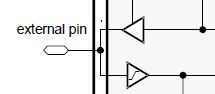
     Below is a simplified IO Pad structure. The input buffer and the output are connected to form the I/O. This means that you can read via the input buffer what you drive on the output buffer as a method of diagnostic test. 


    Bruno, thanks for the tips too. 

  • Bruno Saraiva said:
    I can say that we sometimes monitor the status of a GPIO simply by reading it, i.e. with GPIOPinRead(). Even if configured as an output, this function will return the actual pin status.

    That seems to be contradicted by the description of the GPIO Data (GPIODATA) register in the TM4C1294NCPDT datasheet date June 18, 2014 which says:

    A read from GPIODATA returns the last bit value written if the respective pins are configured as outputs, or it returns the value on the corresponding input pin when these are configured as inputs.

    In a test on a TM4C1294NCPDT in which GPIOPinTypeGPIOOutputOD() was used to set a GPIO to open-drain, once a GPIOPinWrite() had been used to set a 'one' in the GPIODATA register GPIOPinRead() reported the open-drain GPIO as a 'one' even if the actual pin was driven to 'zero' externally to the device.

    i.e. when a GPIO is set to output don't think the software can monitor the actual pin status.

    Without further tests, not sure if an I/O pad being controlled by a peripheral allows the actual pin status to be monitored by a GPIO input.

  • Chester,
    Thanks for the correction. Because we didn't have a bad/shortened board, nor configured it as OD output, we only assumed the reading represented the GPIO level.
    I don't feel like further creating the necessary electric conflict in one of my boards to test the GPIO as standard... It will probably be non-conclusive and burn the pad...
    Sorry for the misleading post - hoping at least it generated a good discussion and added knowledge!
    Cheers
    Bruno
  • Chester Gillon said:
    Without further tests, not sure if an I/O pad being controlled by a peripheral allows the actual pin status to be monitored by a GPIO input.

    Would not that quote read better if written: "If an I/O pad - configured as a GPIO Output - being controlled by a peripheral?..."

    If the pin is configured as an input - it should (always) be possible to monitor pin status - I would think...

  • cb1_mobile said:
    Would not that quote read better if written: "If an I/O pad - configured as a GPIO Output - being controlled by a peripheral?..."

    If the pin is configured as an input - it should (always) be possible to monitor pin status - I would think...

    Agreed.

    I did some more tests on a TM4C1294NCPDT with pins PD0 and PD1 configured as the peripheral functions I2C7SCL and I2C7SDA :

    a) With the GPIO port D GPIODIR bits[1:0] as zero (i.e. inputs) then GPIO port D GPIODATA bits[1:0] read the value on the PD[1:0] pins.

    a) With the GPIO port D GPIODIR bits[1:0] as one (i.e. outputs) then GPIO port D GPIODATA bits[1:0] didn't read the value on the PD[1:0] pins.

    Pins being controlled by the I2C peripheral configured as open-drain were used since could short the pins to ground to check the value read from the GPIODATA registers without causing damage to the output stage.

    Therefore, with a peripheral controlling the output state of a pin it may be possible to read the GPIODATA register to determine if the pin is at the correct state, but the software checking the pin state would have to know what state the peripheral is driving.

  • Like your use of a clever experiment which intends to "avoid potential issues" while gleaning, improved understanding.      (i.e. the "safety" offered by open-drain under I2C)

    You (surely) know this - others may not - "It is most always possible to route a GPIO output to a (separate) GPIO input - if "truly/really" knowing the "moment by moment" state of that GPIO Output IS required...

    Note that this method does, "eat I/O."    In certain of our hi-rel designs - we lessen that "pin eating" by employing a multiplexer IC - which enables the "sacrifice" of just "1" I/O - to monitor as many as 8 GPIO Outputs!     (does involve a "trade-off" - we gain GPIO "Output detection number" - but at the cost of the "time penalty" (delay) - imposed by our scan of the multiplexed channels.)

    If/when one factors in, "Ease of Use" - the "Output tied to Input" method (just described - via direct connect or via mux) usually is ranked quite high...

  • Hi Chester,
    Thanks for running the experiment. For other MCUs I have worked with before, the input pins are normally broadcasted to their receiving peripherals. Mux is needed for the output if shared by peripherals. I wasn't sure about TM4C myself. Thanks for confirming.
  • Hi cb1,
    We have implemented something to certain extent similar to what you suggest in other MCUs. For example, an PWM_A output pin can be routed to another input capture CAP_B pin but the routing is done inside the chip. Unfortunately, TM4C does not have support for internal loopback between different I/Os. But thanks for suggesting your idea to the forum community.
  • You are most welcome Charles - and do note that the, "consistency, simplicity & flexibility" - offered by such (external) circuitry - proves especially critical when the design/delivery is "rushed" - and (all) of the MCU's "secrets" are not (well) found nor disclosed.

    Again - Bravo to Chester for highlighting the advantages of, "User Experiments" which always best focus upon the user's (actual) MCU & system - and provide value (sometimes even "rescue") when, "Forum help has (yet) to arrive!"