Tool/software: Code Composer Studio
Hi all,
I successfully wrote to a 7-Segment display using only 2 wires thanks to I2C. I'm starting to like this protocol. So I decided to use as an input expander, but now I'm facing some problems.
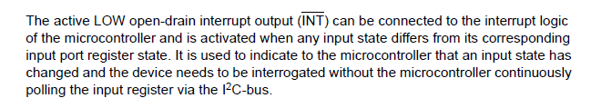
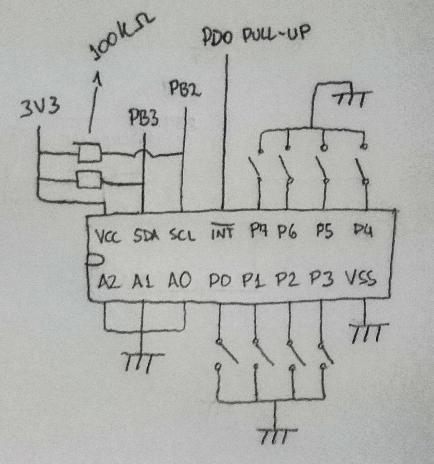
I'm trying to use the PCF8574AP inputs, if I'm not mistaken, when I pull the pins to GND, it should generate an interrupt. Well, it generates indeed, but in the INT port of the chip, not on the Tiva, and the MCU does not get any data from the IC. I tried both Master and Slave modes.
#include <stdbool.h>
#include <stdint.h>
#include "inc/hw_i2c.h"
#include "inc/hw_ints.h"
#include "inc/hw_memmap.h"
#include "inc/hw_types.h"
#include "driverlib/gpio.h"
#include "driverlib/i2c.h"
#include "driverlib/interrupt.h"
#include "driverlib/pin_map.h"
#include "driverlib/sysctl.h"
#include "driverlib/uart.h"
#include "uartstdio.h"

#define SLAVE_ADDRESS           0x38

//*****************************************************************************
//
// Global variable to hold the I2C data that has been received.
//
//*****************************************************************************
static uint32_t g_ui32DataRx;

//*****************************************************************************
//
// This function sets up UART0 to be used for a console to display information
// as the example is running.
//
//*****************************************************************************
void
InitConsole(void)
{
    //
    // Enable GPIO port A which is used for UART0 pins.
    // TODO: change this to whichever GPIO port you are using.
    //
    SysCtlPeripheralEnable(SYSCTL_PERIPH_GPIOA);

    //
    // Configure the pin muxing for UART0 functions on port A0 and A1.
    // This step is not necessary if your part does not support pin muxing.
    // TODO: change this to select the port/pin you are using.
    //
    GPIOPinConfigure(GPIO_PA0_U0RX);
    GPIOPinConfigure(GPIO_PA1_U0TX);

    //
    // Enable UART0 so that we can configure the clock.
    //
    SysCtlPeripheralEnable(SYSCTL_PERIPH_UART0);

    //
    // Use the internal 16MHz oscillator as the UART clock source.
    //
    UARTClockSourceSet(UART0_BASE, UART_CLOCK_PIOSC);

    //
    // Select the alternate (UART) function for these pins.
    // TODO: change this to select the port/pin you are using.
    //
    GPIOPinTypeUART(GPIO_PORTA_BASE, GPIO_PIN_0 | GPIO_PIN_1);

    //
    // Initialize the UART for console I/O.
    //
    UARTStdioConfig(0, 115200, 16000000);
}

//*****************************************************************************
//
// The interrupt handler for the for I2C0 data slave interrupt.
//
//*****************************************************************************
void
I2C0MasterIntHandler(void)
{
    //
    // Clear the I2C0 interrupt flag.
    //
    I2CMasterIntClear(I2C0_BASE);

    //
    // Read the data from the slave.
    //
    g_ui32DataRx = I2CMasterDataGet(I2C0_BASE);

    //
    // Display that interrupt was received.
    //
    UARTprintf("\n  Master Interrupt Received!\n");

    //
    // Display the data that the slave has received.
    //
    UARTprintf("  Received: '%s'\n\n", g_ui32DataRx);
}

int main(void)
{
    //init clock and periph
    SysCtlClockSet(SYSCTL_SYSDIV_1 | SYSCTL_USE_OSC | SYSCTL_OSC_MAIN | SYSCTL_XTAL_16MHZ);

    SysCtlPeripheralEnable(SYSCTL_PERIPH_I2C0);
    SysCtlPeripheralEnable(SYSCTL_PERIPH_GPIOB);

    GPIOPinConfigure(GPIO_PB2_I2C0SCL);
    GPIOPinConfigure(GPIO_PB3_I2C0SDA);

    GPIOPinTypeI2CSCL(GPIO_PORTB_BASE, GPIO_PIN_2);
    GPIOPinTypeI2C(GPIO_PORTB_BASE, GPIO_PIN_3);

    //
    // Enable the I2C0 interrupt on the processor (NVIC).
    //
    IntEnable(INT_I2C0);

    //
    // Configure and turn on the I2C0 slave interrupt.  The I2CSlaveIntEnableEx()
    // gives you the ability to only enable specific interrupts.  For this case
    // we are only interrupting when the slave device receives data.
    //
    I2CMasterIntEnableEx(I2C0_BASE, I2C_MASTER_INT_DATA);

    //
    // Enable and initialize the I2C0 master module.  Use the system clock for
    // the I2C0 module.  The last parameter sets the I2C data transfer rate.
    // If false the data rate is set to 100kbps and if true the data rate will
    // be set to 400kbps.  For this example we will use a data rate of 100kbps.
    //
    I2CMasterInitExpClk(I2C0_BASE, SysCtlClockGet(), false);


    //
    // Tell the master module what address it will place on the bus when
    // communicating with the slave.  Set the address to SLAVE_ADDRESS
    // (as set in the slave module).  The receive parameter is set to false
    // which indicates the I2C Master is initiating a writes to the slave.  If
    // true, that would indicate that the I2C Master is initiating reads from
    // the slave.
    //
    I2CMasterSlaveAddrSet(I2C0_BASE, SLAVE_ADDRESS, true);

    //
    // Set up the serial console to use for displaying messages.  This is just
    // for this example program and is not needed for proper I2C operation.
    //
    InitConsole();

    //
    // Enable interrupts to the processor.
    //
    IntMasterEnable();

    //
    // Display the example setup on the console.
    //
    UARTprintf("I2C Master Interrupt Example ->");
    UARTprintf("\n   Module = I2C0");
    UARTprintf("\n   Mode = Receive interrupt on the Master module");
    UARTprintf("\n   Rate = 100kbps\n\n");

    //
    //tried to read without interrupt
    //

    SysCtlDelay(SysCtlClockGet()/3);

    //
    // Read the data from the master.
    //
    g_ui32DataRx = I2CMasterDataGet(I2C0_BASE);

    //
    // Display that data was received.
    //
    UARTprintf("\n  Master Data Received!\n");

    //
    // Display the data that the master has received.
    //
    UARTprintf("  Received: '%s'\n\n", g_ui32DataRx);

    while(1);
}
As a Slave interrupt:
#include <stdbool.h>
#include <stdint.h>
#include "inc/hw_i2c.h"
#include "inc/hw_ints.h"
#include "inc/hw_memmap.h"
#include "inc/hw_types.h"
#include "driverlib/gpio.h"
#include "driverlib/i2c.h"
#include "driverlib/interrupt.h"
#include "driverlib/pin_map.h"
#include "driverlib/sysctl.h"
#include "driverlib/uart.h"
#include "uartstdio.h"

#define SLAVE_ADDRESS           0x38

//*****************************************************************************
//
// Global variable to hold the I2C data that has been received.
//
//*****************************************************************************
static uint32_t g_ui32DataRx;

//*****************************************************************************
//
// This function sets up UART0 to be used for a console to display information
// as the example is running.
//
//*****************************************************************************
void
InitConsole(void)
{
    //
    // Enable GPIO port A which is used for UART0 pins.
    // TODO: change this to whichever GPIO port you are using.
    //
    SysCtlPeripheralEnable(SYSCTL_PERIPH_GPIOA);

    //
    // Configure the pin muxing for UART0 functions on port A0 and A1.
    // This step is not necessary if your part does not support pin muxing.
    // TODO: change this to select the port/pin you are using.
    //
    GPIOPinConfigure(GPIO_PA0_U0RX);
    GPIOPinConfigure(GPIO_PA1_U0TX);

    //
    // Enable UART0 so that we can configure the clock.
    //
    SysCtlPeripheralEnable(SYSCTL_PERIPH_UART0);

    //
    // Use the internal 16MHz oscillator as the UART clock source.
    //
    UARTClockSourceSet(UART0_BASE, UART_CLOCK_PIOSC);

    //
    // Select the alternate (UART) function for these pins.
    // TODO: change this to select the port/pin you are using.
    //
    GPIOPinTypeUART(GPIO_PORTA_BASE, GPIO_PIN_0 | GPIO_PIN_1);

    //
    // Initialize the UART for console I/O.
    //
    UARTStdioConfig(0, 115200, 16000000);
}

//*****************************************************************************
//
// The interrupt handler for the for I2C0 data slave interrupt.
//
//*****************************************************************************
void
I2C0SlaveIntHandler(void)
{
    //
    // Clear the I2C0 interrupt flag.
    //
    I2CSlaveIntClear(I2C0_BASE);

    //
    // Read the data from the slave.
    //
    g_ui32DataRx = I2CSlaveDataGet(I2C0_BASE);

    //
    // Display that interrupt was received.
    //
    UARTprintf("\n  Slave Interrupt Received!\n");

    //
    // Display the data that the slave has received.
    //
    UARTprintf("  Received: '%s'\n\n", g_ui32DataRx);
}

int main(void)
{
    //init clock and periph
    SysCtlClockSet(SYSCTL_SYSDIV_1 | SYSCTL_USE_OSC | SYSCTL_OSC_MAIN | SYSCTL_XTAL_16MHZ);

    SysCtlPeripheralEnable(SYSCTL_PERIPH_I2C0);
    SysCtlPeripheralEnable(SYSCTL_PERIPH_GPIOB);

    GPIOPinConfigure(GPIO_PB2_I2C0SCL);
    GPIOPinConfigure(GPIO_PB3_I2C0SDA);

    GPIOPinTypeI2CSCL(GPIO_PORTB_BASE, GPIO_PIN_2);
    GPIOPinTypeI2C(GPIO_PORTB_BASE, GPIO_PIN_3);

    //
    // Enable the I2C0 interrupt on the processor (NVIC).
    //
    IntEnable(INT_I2C0);

    //
    // Configure and turn on the I2C0 slave interrupt.  The I2CSlaveIntEnableEx()
    // gives you the ability to only enable specific interrupts.  For this case
    // we are only interrupting when the slave device receives data.
    //
    I2CSlaveIntEnableEx(I2C0_BASE, I2C_SLAVE_INT_DATA);

    //
    // Enable and initialize the I2C0 master module.  Use the system clock for
    // the I2C0 module.  The last parameter sets the I2C data transfer rate.
    // If false the data rate is set to 100kbps and if true the data rate will
    // be set to 400kbps.  For this example we will use a data rate of 100kbps.
    //
    I2CMasterInitExpClk(I2C0_BASE, SysCtlClockGet(), false);

    //
    // Enable the I2C0 slave module.
    //
    I2CSlaveEnable(I2C0_BASE);

    //
    // Set the slave address to SLAVE_ADDRESS.  In loopback mode, it's an
    // arbitrary 7-bit number (set in a macro above) that is sent to the
    // I2CMasterSlaveAddrSet function.
    //
    I2CSlaveInit(I2C0_BASE, SLAVE_ADDRESS);

    //
    // Tell the master module what address it will place on the bus when
    // communicating with the slave.  Set the address to SLAVE_ADDRESS
    // (as set in the slave module).  The receive parameter is set to false
    // which indicates the I2C Master is initiating a writes to the slave.  If
    // true, that would indicate that the I2C Master is initiating reads from
    // the slave.
    //
    I2CMasterSlaveAddrSet(I2C0_BASE, SLAVE_ADDRESS, true);

    //
    // Set up the serial console to use for displaying messages.  This is just
    // for this example program and is not needed for proper I2C operation.
    //
    InitConsole();

    //
    // Enable interrupts to the processor.
    //
    IntMasterEnable();

    //
    // Display the example setup on the console.
    //
    UARTprintf("I2C Slave Interrupt Example ->");
    UARTprintf("\n   Module = I2C0");
    UARTprintf("\n   Mode = Receive interrupt on the Slave module");
    UARTprintf("\n   Rate = 100kbps\n\n");

    //
    //tried to read without interrupt
    //

    SysCtlDelay(SysCtlClockGet()/3);
    //
    // Read the data from the slave.
    //
    g_ui32DataRx = I2CSlaveDataGet(I2C0_BASE);

    //
    // Display that data was received.
    //
    UARTprintf("\n  Slave Data Received!\n");

    //
    // Display the data that the slave has received.
    //
    UARTprintf("  Received: '%s'\n\n", g_ui32DataRx);

    while(1);
}
I'm configuring the device incorrectly?
Thanks