This thread has been locked.

If you have a related question, please click the "Ask a related question" button in the top right corner. The newly created question will be automatically linked to this question.

CCS/TM4C129ENCPDT: Signal generation with PWM

Part Number: TM4C129ENCPDT

Tool/software: Code Composer Studio

Hello, I need to generate five diferent signals of (10 20 30 40 45) KHz,  I have configurate two PWM outputs to generate for me the 20 and 40 KHz signal, but at the output only the first signal have the right period, the second one have the same period of the first but with a duty cycle modification although I have configurate both with  50% of duty cycle. Here is the code:

#include <stdint.h>
#include <stdbool.h>
#include "inc/hw_ints.h"
#include "inc/hw_memmap.h"
#include "inc/hw_types.h"

#include "driverlib/debug.h"
#include "driverlib/fpu.h"
#include "driverlib/gpio.h"
#include "driverlib/interrupt.h"
#include "driverlib/pin_map.h"
#include "driverlib/rom.h"
#include "driverlib/rom_map.h"

#include "driverlib/pwm.h"
#include "driverlib/sysctl.h"
#include "driverlib/timer.h"

uint32_t g_ui32FlagsF;

int main(void)
{

    g_ui32SysClock = MAP_SysCtlClockFreqSet((SYSCTL_XTAL_25MHZ |
                                             SYSCTL_OSC_MAIN |
                                             SYSCTL_USE_PLL |
                                             SYSCTL_CFG_VCO_480), 120000000);

    SysCtlPWMClockSet(SYSCTL_PWMDIV_1);

    SysCtlPeripheralEnable(SYSCTL_PERIPH_PWM0);
    SysCtlPeripheralEnable(SYSCTL_PERIPH_PWM1);

    SysCtlPeripheralEnable(SYSCTL_PERIPH_GPIOF);

    GPIOPinConfigure(GPIO_PF0_M0PWM0);
    GPIOPinConfigure(GPIO_PF1_M0PWM1);

    GPIOPinTypePWM(GPIO_PORTF_BASE, GPIO_PIN_0);
    GPIOPinTypePWM(GPIO_PORTF_BASE, GPIO_PIN_1);

    PWMGenConfigure(PWM0_BASE, PWM_GEN_0, PWM_GEN_MODE_DOWN | PWM_GEN_MODE_SYNC);
    PWMGenConfigure(PWM0_BASE, PWM_GEN_1, PWM_GEN_MODE_DOWN | PWM_GEN_MODE_SYNC);

    PWMGenPeriodSet(PWM0_BASE, PWM_GEN_0, 6000);
    PWMGenPeriodSet(PWM0_BASE, PWM_GEN_1, 3000);

    PWMPulseWidthSet(PWM0_BASE, PWM_OUT_0,PWMGenPeriodGet(PWM0_BASE, PWM_GEN_0) / (2));
    PWMOutputState(PWM0_BASE, PWM_OUT_0_BIT, true);
    PWMGenEnable(PWM0_BASE, PWM_GEN_0);

    PWMPulseWidthSet(PWM0_BASE, PWM_OUT_1,PWMGenPeriodGet(PWM0_BASE, PWM_GEN_1) / (2));
    PWMOutputState(PWM0_BASE, PWM_OUT_1_BIT, true);
    PWMGenEnable(PWM0_BASE, PWM_GEN_1);
    while(1)
    {
    }
}

I want to know if it is going to be possible to generate the 5 signals each with their respective period using PWM.

  • While we don't use that MCU - I believe that the individual "PWM Generators" can support up to TWO PWM Outputs - each/either of "user programmable Duty Cycle" - but (both) set to the SAME frequency/period!

    This then requires the (direct) use of "five" such PWM Generators - to yield "five different" PWM frequencies/periods.   (I am 90%+ "sure of this" (Do not bet the farm))

    What to do then?    (assuming that your MCU does not contain 5 independent, PWM Generators)

    • Timer set to PWM mode provides "reasonable" PWM capability.    (lacks the fine/full control of the PWM Generator)
    • It may be possible to route your 40KHz PWM output signal into a "Timer input" pin - and implement a "Divide by two" (yielding your required 20KHz) AND a "Divide by four" (yielding your required 10KHz).    I suspect this would be simpler/faster to achieve via a simple "flip-flop" (surely would integrally divide the frequency) I'm unsure if the duty cycle would be maintained - although the "FF" would clock on signal edges - which almost insures the PWM modulation would be lost!
    • Surest thing (after running "off the rails", just above) would see you employ four PWM Generators (w/in one PWM Module) yielding four of your required Freq. PWM signals - and the fifth via the 2nd PWM Module (believe that to be "PWM1_Base" or via one of your Timers - again forced into PWM mode.

    I'm claiming "distraction, or temporary insanity" for "bullet #2" (above) which I (now) believe has "no chance" of maintaining the duty cycle - outputting 50% duty (only), instead.

    It is good that "instructor, boss, someone" enabled your use of the advantaged API - and not the "S L O W    M O T I O N" - exhausting (upon you and helpers) - and error-laden (otherwise "delightful") DRM.

    While this IS an MCU-Centric forum - application like this may prove faster/easier/better to implement via hardware (FPGA or CPLD).     MCU cannot do everything w/efficiency!     (hello Mr./Ms. Moderator)

  • Sergio,
    Take a look at this post, which will help you sort out the PWM terminology.
    e2e.ti.com/.../2034434
    I'm almost sure you can do what you want with PWM's... Hope you did get the peripherals all hooked into convenient pins!
    Regards
    Bruno
  • Yet - as poster "succeeded" w/two different PWM Generator Outputs - can his issue (really) be "terminology?"

    Might it - more likely - be, "inability to produce different frequency/period upon the 2 outputs" of a single PWM Generator?   

    Again - the duty cycle is individually adjustable - yet the PWM Frequency/Period is (necessarily) SHARED!   (within any, dual channel, PWM Generator)

  • cb1,

    Poster's issue can be terminology, difficulty to configure the outputs, or maybe even just a regular cold - hard to determine from here... But a deeper reading into PWM issues from a previous post won't hurt.

    That particular p/n has "One Pulse Width Modulator (PWM) module, with four PWM generator blocks and a control block, for a total of 8 PWM outputs"

    Since there are 4 generator blocks, he can certainly create 4 different periods. The 5th would need to be created with a timer - not a big deal, just use the timer on PWM mode.

    Those macros used as configuration for the PWM are tricky (as in easy-to-confuse), for they have similar names - so while I can't reproduce/test his code right now, I believe the problem is probably just a bad parameter...

    Piece,

    Bruno

  • Hi cb1, Bruno,
    Thanks. You are always faster than I can respond. :-)

    Hi Sergio,
    Like cb1 and Bruno said, each GEN block controls two PWMs and that means they share the same timebase/frequency. You can produce two different duty cycles out of the two PWMs from each GEN block.

    Are you seeing 25% duty cycle out of PWM_OUT_1?

    In your below line you try to set the duty cycle of PWM_OUT_1 to be 50% of the period for GEN_1. Note that PWM_OUT_0 and PWM_OUT_1 shares the same GEN_0. Since the GEN_1 period is half of of GEN_0 and therefore, you should see 25% duty cycle on PWM_OUT_1.

    PWMPulseWidthSet(PWM0_BASE, PWM_OUT_1,PWMGenPeriodGet(PWM0_BASE, PWM_GEN_1) / (2));
  • Charles Tsai said:
    Thanks. You are always faster than I can respond. :-)

    In my case - at least - that is (only) because I'm near San Francisco this day - and my direction of travel - is "downhill."

    Instructor, Trainer, Boss "must have known" (as Bruno confirmed) that this MCU has "only" four PWM Generators - thus some "indirection" is required to realize the 5th PWM output.

    And - my (first post here - in response) indeed suggested use of "Timer in PWM Mode" to meet "Instructor, Trainer, Boss" requirement...

    Oh and Charles - is not cb1 "so well wired in" as to know that "cohort Bob" - is readying for that "famed event" - First Saturday in May - which dawns, tomorrow in KY?     (cb1 too - will make that journey)

  • Bruno my friend - and "introducer of Meter."      We must agree to disagree.       And interestingly (at least to you/me) your "Terminology" argument makes great sense - when aimed at "meter."

    Yet - the facts lean (fairly heavily) to my (court-room) side - as poster absolutely got FOUR PWM Signals to work - his ONLY inability was to achieve INDEPENDENT FREQUENCY UPON INDIVIDUAL PWM GENERATORS!        Which you, Charles and this reporter - all agree - cannot be done.     Thus - there is NO/ZERO "Terminology Shortcoming" - his PWM Outputs performed!

    To (completely) "break the back" of your "terminology plea" - exactly HOW could poster have achieved, "Individual Frequency Control of EACH PWM Output - w/in the same Generator?"     Which terminology definition well defined/described - "individual frequency control?"      Clearly - there are NONE!        Thus the issue is one of "Understanding" not terminology!

    Indeed your (past) effort in better identifying the "ins/outs" of PWM "nomenclature" (0.25 (USD) for that word) were helpful - but poster (again) got PWM Output on his own!    His only "failure" was achieving four different frequencies - which even your "good" (yet past post) could not rectify!     And - I DO recall - being one (maybe the only one) who acknowledged & applauded your past post.     But - it was NOT IN PLAY here - today!

    I don't believe that MCU manual or Driver Lib User Guide ever (specifically) state/advise that while, "Duty Cycles w/in a Gen may be independently set - frequency is common!"     At (some) point such may be added - but unlikely anytime soon - as "PF0/PD7 Assault upon Users" continues to wreak harm (is it 5 years, now) across the "NMI fruited plain."

  • cb1_mobile said:
    that "famed event" - First Saturday in May - which dawns, tomorrow in KY?  

    Hope to see another American Pharoah. Enjoy!, I will be on the plane tomorrow. :-)

  • Sergio,

    There's nothing "luckier" than cb1 telling me something can't be done when it can.

    Here's your code, enjoy. Sorry I didn't have time to add the timer configuration for the 45KHz signal as well... past 10PM here.

    If you have an EK-TM4C1294 launchpad, the signals will be on headers C1-1, C1-2, C1-4 and C2-3.

    Regards

    Bruno

    #include "main_PWM01.h"
    
    uint32_t systemClock;
    
    void main(void)
    {
        systemClock = SysCtlClockFreqSet((SYSCTL_XTAL_25MHZ | SYSCTL_OSC_MAIN | SYSCTL_USE_PLL | SYSCTL_CFG_VCO_480), 120000000);
    
        SysCtlPeripheralEnable(SYSCTL_PERIPH_GPIOF);
        while(!(SysCtlPeripheralReady(SYSCTL_PERIPH_GPIOF)));
        SysCtlPeripheralEnable(SYSCTL_PERIPH_GPIOG);
        while(!(SysCtlPeripheralReady(SYSCTL_PERIPH_GPIOG)));
        SysCtlPeripheralEnable(SYSCTL_PERIPH_GPIOK);
        while(!(SysCtlPeripheralReady(SYSCTL_PERIPH_GPIOK)));
        SysCtlPWMClockSet(SYSCTL_PWMDIV_1);
        SysCtlPeripheralDisable(SYSCTL_PERIPH_PWM0);
        SysCtlPeripheralReset(SYSCTL_PERIPH_PWM0);
        SysCtlPeripheralEnable(SYSCTL_PERIPH_PWM0);
        while(!(SysCtlPeripheralReady(SYSCTL_PERIPH_PWM0)));
        // Read this for explanation: e2e.ti.com/.../344373
        // PWM0_BASE: 0 is the 0 from M0PWM3 on the pin name
        // PWM_OUT_3 and PWM_OUT_3_BIT: 3 is the 3 from M0PWM3 on the pin name
        // PWM_GEN_1: GEN_0 is for PWM0 and PWM1, GEN_1 for PWM2 and PWM3, GEN_2 for PWM4 and PWM5, GEN_3 for PWM6 and PWM7
        GPIOPinTypePWM(GPIO_PORTF_BASE, GPIO_PIN_1 | GPIO_PIN_2);
        GPIOPinTypePWM(GPIO_PORTG_BASE, GPIO_PIN_0);
        GPIOPinTypePWM(GPIO_PORTK_BASE, GPIO_PIN_5);
        GPIOPinConfigure(GPIO_PF1_M0PWM1);
        GPIOPinConfigure(GPIO_PF2_M0PWM2);
        GPIOPinConfigure(GPIO_PG0_M0PWM4);
        GPIOPinConfigure(GPIO_PK5_M0PWM7);
        PWMGenConfigure(PWM0_BASE, PWM_GEN_0, PWM_GEN_MODE_DOWN | PWM_GEN_MODE_NO_SYNC | PWM_GEN_MODE_DBG_RUN);
        PWMGenConfigure(PWM0_BASE, PWM_GEN_1, PWM_GEN_MODE_DOWN | PWM_GEN_MODE_NO_SYNC | PWM_GEN_MODE_DBG_RUN);
        PWMGenConfigure(PWM0_BASE, PWM_GEN_2, PWM_GEN_MODE_DOWN | PWM_GEN_MODE_NO_SYNC | PWM_GEN_MODE_DBG_RUN);
        PWMGenConfigure(PWM0_BASE, PWM_GEN_3, PWM_GEN_MODE_DOWN | PWM_GEN_MODE_NO_SYNC | PWM_GEN_MODE_DBG_RUN);
        PWMGenPeriodSet(PWM0_BASE, PWM_GEN_0, systemClock/10000);
        PWMGenPeriodSet(PWM0_BASE, PWM_GEN_1, systemClock/20000);
        PWMGenPeriodSet(PWM0_BASE, PWM_GEN_2, systemClock/30000);
        PWMGenPeriodSet(PWM0_BASE, PWM_GEN_3, systemClock/40000);
        PWMPulseWidthSet(PWM0_BASE, PWM_OUT_1, systemClock/20000);
        PWMPulseWidthSet(PWM0_BASE, PWM_OUT_2, systemClock/40000);
        PWMPulseWidthSet(PWM0_BASE, PWM_OUT_4, systemClock/60000);
        PWMPulseWidthSet(PWM0_BASE, PWM_OUT_7, systemClock/80000);
        PWMGenEnable(PWM0_BASE, PWM_GEN_0);
        PWMGenEnable(PWM0_BASE, PWM_GEN_1);
        PWMGenEnable(PWM0_BASE, PWM_GEN_2);
        PWMGenEnable(PWM0_BASE, PWM_GEN_3);
        PWMOutputState(PWM0_BASE, PWM_OUT_1_BIT | PWM_OUT_2_BIT | PWM_OUT_4_BIT | PWM_OUT_7_BIT, true);
        while(1)
        {
        }
    }
    

  • Bruno Saraiva said:
    there are four PWM Generators - they need NOT share a frequency!

    Bruno - you battle on - as clearly stated - first by moi - then Charles - that SHARED FREQUENCY occurs w/in a Single PWM Generator!      (as a "terminology maven" you (should) know that.)

    Thus - even w/four PWM Generators - only four PWM output frequencies may result.    Which I noted - the (very) first post.

    So - we must chalk it up to a "too tired Bruno" to misstate a "cb1 claim."    Again - that was, " that SHARED FREQUENCY occurs w/in a Single PWM Generator!"


    Where/how do you believe that I told you that "something cannot be done - when it can?"      That would prove true ONLY if you could coax two different frequencies from a single PWM Generator - which of course - you cannot!

    Feel free to first find - then accurately quote me - while proving that you CAN do it.     (which we know - you cannot)

    So sleep well - so that (maybe) you'll be more mistake free - tomorrow - as the horses gallop and cb1 team indulges in "Mint Juleps."      (likely well mixed/prepared - via a single frequency PWM SHARED by both outputs w/in a SINGLE PWM GENERATOR!)

  • Greetings cb1, good day fellows,

    I stand corrected, you never said one generator can provide two different frequencies - my apologies. Friday nights certainly don't help an attempt for fast readings, and I got the impression that you had said what poster wanted was not possible!

    As to OP's first request, since it won't hurt to provide a simple example, here's the code which can generate all 5 frequencies he needs:

    #include "main_PWM01.h"
    
    uint32_t systemClock;
    
    void main(void)
    {
        systemClock = SysCtlClockFreqSet((SYSCTL_XTAL_25MHZ | SYSCTL_OSC_MAIN | SYSCTL_USE_PLL | SYSCTL_CFG_VCO_480), 120000000);
    
        SysCtlPeripheralEnable(SYSCTL_PERIPH_GPIOF);
        while(!(SysCtlPeripheralReady(SYSCTL_PERIPH_GPIOF)));
        SysCtlPeripheralEnable(SYSCTL_PERIPH_GPIOG);
        while(!(SysCtlPeripheralReady(SYSCTL_PERIPH_GPIOG)));
        SysCtlPeripheralEnable(SYSCTL_PERIPH_GPIOK);
        while(!(SysCtlPeripheralReady(SYSCTL_PERIPH_GPIOK)));
    
        SysCtlPWMClockSet(SYSCTL_PWMDIV_1);
        SysCtlPeripheralDisable(SYSCTL_PERIPH_PWM0);
        SysCtlPeripheralReset(SYSCTL_PERIPH_PWM0);
        SysCtlPeripheralEnable(SYSCTL_PERIPH_PWM0);
        while(!(SysCtlPeripheralReady(SYSCTL_PERIPH_PWM0)));
        // Read this for explanation: e2e.ti.com/.../344373
        // PWM0_BASE: 0 is the 0 from M0PWM3 on the pin name
        // PWM_OUT_3 and PWM_OUT_3_BIT: 3 is the 3 from M0PWM3 on the pin name
        // PWM_GEN_1: GEN_0 is for PWM0 and PWM1, GEN_1 for PWM2 and PWM3, GEN_2 for PWM4 and PWM5, GEN_3 for PWM6 and PWM7
        GPIOPinTypePWM(GPIO_PORTF_BASE, GPIO_PIN_1 | GPIO_PIN_2);
        GPIOPinTypePWM(GPIO_PORTG_BASE, GPIO_PIN_0);
        GPIOPinTypePWM(GPIO_PORTK_BASE, GPIO_PIN_5);
        GPIOPinConfigure(GPIO_PF1_M0PWM1);
        GPIOPinConfigure(GPIO_PF2_M0PWM2);
        GPIOPinConfigure(GPIO_PG0_M0PWM4);
        GPIOPinConfigure(GPIO_PK5_M0PWM7);
        PWMGenConfigure(PWM0_BASE, PWM_GEN_0, PWM_GEN_MODE_DOWN | PWM_GEN_MODE_NO_SYNC | PWM_GEN_MODE_DBG_RUN);
        PWMGenConfigure(PWM0_BASE, PWM_GEN_1, PWM_GEN_MODE_DOWN | PWM_GEN_MODE_NO_SYNC | PWM_GEN_MODE_DBG_RUN);
        PWMGenConfigure(PWM0_BASE, PWM_GEN_2, PWM_GEN_MODE_DOWN | PWM_GEN_MODE_NO_SYNC | PWM_GEN_MODE_DBG_RUN);
        PWMGenConfigure(PWM0_BASE, PWM_GEN_3, PWM_GEN_MODE_DOWN | PWM_GEN_MODE_NO_SYNC | PWM_GEN_MODE_DBG_RUN);
        PWMGenPeriodSet(PWM0_BASE, PWM_GEN_0, systemClock/10000);
        PWMGenPeriodSet(PWM0_BASE, PWM_GEN_1, systemClock/20000);
        PWMGenPeriodSet(PWM0_BASE, PWM_GEN_2, systemClock/30000);
        PWMGenPeriodSet(PWM0_BASE, PWM_GEN_3, systemClock/40000);
        PWMPulseWidthSet(PWM0_BASE, PWM_OUT_1, systemClock/20000);
        PWMPulseWidthSet(PWM0_BASE, PWM_OUT_2, systemClock/40000);
        PWMPulseWidthSet(PWM0_BASE, PWM_OUT_4, systemClock/60000);
        PWMPulseWidthSet(PWM0_BASE, PWM_OUT_7, systemClock/80000);
        PWMGenEnable(PWM0_BASE, PWM_GEN_0);
        PWMGenEnable(PWM0_BASE, PWM_GEN_1);
        PWMGenEnable(PWM0_BASE, PWM_GEN_2);
        PWMGenEnable(PWM0_BASE, PWM_GEN_3);
        PWMOutputState(PWM0_BASE, PWM_OUT_1_BIT | PWM_OUT_2_BIT | PWM_OUT_4_BIT | PWM_OUT_7_BIT, true);
    
        SysCtlPeripheralEnable(SYSCTL_PERIPH_GPIOD);
        while(!(SysCtlPeripheralReady(SYSCTL_PERIPH_GPIOD)));
        SysCtlPeripheralDisable(SYSCTL_PERIPH_TIMER1);
        SysCtlPeripheralReset(SYSCTL_PERIPH_TIMER1);
        SysCtlPeripheralEnable(SYSCTL_PERIPH_TIMER1);
        while(!(SysCtlPeripheralReady(SYSCTL_PERIPH_TIMER1)));
        GPIOPinTypeTimer(GPIO_PORTD_BASE, GPIO_PIN_3);
        GPIOPinConfigure(GPIO_PD3_T1CCP1);
        TimerConfigure(TIMER1_BASE, TIMER_CFG_SPLIT_PAIR | TIMER_CFG_B_PWM);
        TimerLoadSet(TIMER1_BASE, TIMER_B, systemClock/45000);
        TimerMatchSet(TIMER1_BASE, TIMER_B, systemClock/90000);
        TimerControlLevel(TIMER1_BASE, TIMER_B, false); // Just an example to make the timer PWM active high
        TimerEnable(TIMER1_BASE, TIMER_B);
    
        while(1)
        {
        }
    }

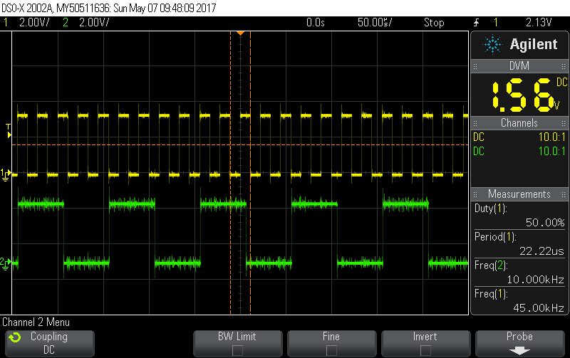
    On the EK-TM4C1294 launchpad, the signals will be on headers C1-1, C1-2, C1-4, C2-3 (for the PWM signals), plus A1-7 for the 45KHz Timer PWM. And an image showing two of the channels below, one at 10KHz and the other at 45KHz - no more channels available on this scope and I won't set up a logic anaylzer today:

    Regards

    Bruno

  • Hi Bruno,

    You've gone (again) "above/beyond" - good job - poster should much appreciate.    (I did note - your earlier code set Sys Clk to 120MHz - yet your "PWM Divides" were "100MHz" based...)   (i.e. div by 10,000)

    As "Blood Alcohol count reduces" - it dawns that "instructor/boss/cohort" may have known of the "Four PWM Generator Limit" (which you identified) and sought to see, "How or If" our poster could overcome.

    Considering that (both) you/I have "sacrificed all four PWM Generators" - might use of (just) 2.5 MCU Timers have proved, "Less MCU capability absorbing" - while (still) meeting poster's, "Five PWM output objectives?"     (I think so - as we've "squandered" 4 PWM Outputs via our choice of PWM Generators - and there is no justification for employing the power & capability of the PWM Generators in this (simple) task.)

    it would prove of interest if poster could request "instructor/boss/cohort's" comment as to, "Why 5 PWM outputs were sought?"

    I'm with you, Bruno - Logic Analyzer unlikely to come alive in Chicago - as well.    (assumes small craft overflies mountains - returns safely later today...)

  • Good day cb1,

    Small craft certainly overflies lots of mountains - or in some cases, go around them - either way I do trust these little machines with my life!

    Now, if OP was related to some sort of school exercise - which I might have ruined, in that case - I'd like to leave a couple of challenges hanging:

    - Make ALL 5 signals synchronized.

    - Configure two of the outputs for slower signals: one at 1000Hz and one at 500Hz.

    Then the student will get my good-to-proceed for his next level.

    Bruno

  • Further to the previous reply: yes, I agree that it is "less consuming" to use TCCP's for these simple PWM signals rather than the PWM hardware itself.

    Is this reading correct, as for which one to choose in a project?

    - PWM hardwares have special features such as direct synchronization, guaranteed dead bands, and easy to obtain opposite signals from one single generator - they have features specially focused for motion control. There is only 1 block with 4 generators in most part numbers - some have none, a few (if any) have two.
    - Timers are simple multi-purpose beasts, and as the codes on this post prove, can also generate square pulses very easily. They are much more abundant in TM4C's, and it is easier to find a TCCP available than it is to find a PWM pin.

    Anyway, just some considerations that I do have on that pinmuxxing phase of a project...

    Bruno
  • I'd change "PWM hardware" to "PWM Generator based hardware."
    And - unless (many) of the "features" of the PWM Gen. are required - use of the, "Less capable resource" (i.e. Timer) meets textbook approval...