Part Number: TM4C123GH6PM
Other Parts Discussed in Thread: EK-TM4C123GXL
Tool/software: TI C/C++ Compiler
I have written the code on Keil uVision4, I'm trying to use #UART1. But I'm unable to find the mistake in my code written below. I've have also used the same code with some required changes in the values of Registers and replacing #UART1 with #UART0 (earlier used UAT0), for blinking the LED on #PortF. That code worked good.
But now, I'm facing problems with UART1 and don't understand what the problem is in the code. I think I'm doing wrong with the Register
GPIOD->PCTL = (GPIOB->PCTL&0xFFFFFF00)+0x00000040; //GPIO PORTB 0-1
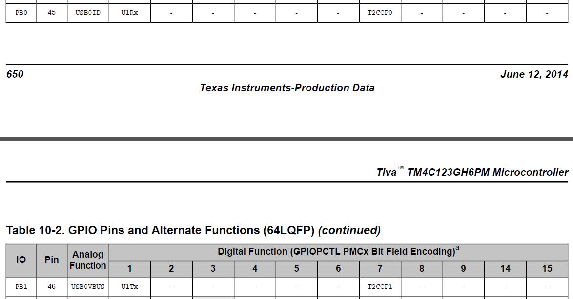
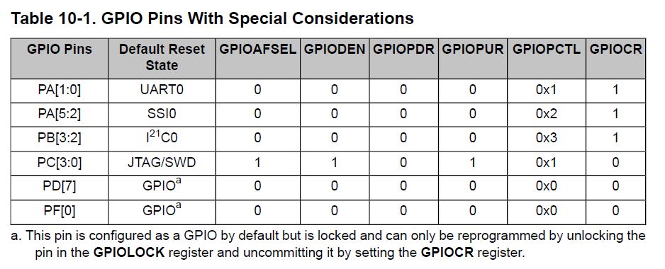
Please guide me, for now I'm trying to use UART1 for blinking LED on PortF because I want to interface GSM with TM4C123GH6PM launchpad as there are no external Pins for Rx and Tx of UART0, that's why I want to use UART1 with Rx and Tx on Pins PB0 and PB1.
#include <stdint.h>
#include <TM4C123GH6PM.H>
void PLL_Init(void);
void UART1_Init(void);
void PortF_Init(void);
void UartWrite(char *pstr);
unsigned char Receiver(void);
void Transmitter(unsigned char data);
int main(void){
unsigned char command;
PLL_Init();
UART1_Init();
PortF_Init();
UartWrite("This program control LEDs on PortF through UART.\r\n");
while(1)
{
UartWrite("Enter Command \'0\',\'1\',\'2\',\'3\':");
UartWrite("AT");
command = Receiver();
Transmitter(command);
UartWrite("AT\r\n");
switch (command){
case '0':
GPIOF->DATA = 0x00;
break;
case '1':
GPIOF->DATA = 0x02;
break;
case '2':
GPIOF->DATA = 0x04;
break;
case '3':
GPIOF->DATA = 0x08;
break;
default:
UartWrite("Wrong command ! \r\n");
break;
}
}
void UART1_Init(void)
{
SYSCTL->RCGCUART |= 0x00000002; //UART1
SYSCTL->RCGCGPIO |= 0x00000002; //PORTB CLOCK ENABLE
UART1->CTL &= ~0x00000002; //UART1 DISABLE
UART0->IBRD = 43; //BAUD INTEGER
UART1->FBRD = 26; //BAUD FLOATING
UART1->LCRH = 0x00000070; //ENABLE FEN & WLEN
UART1->CTL |= 0x01; //UART ENABLE;
GPIOB->AFSEL |= 0x03; // OTHER ALTERNATIVE FUNCTION AT PORTB 0-1
GPIOB->DEN |= 0x02; // PORTB 0-1 OUTPUT
GPIOB->PCTL = (GPIOB->PCTL&0xFFFFFF00)+0x00000040; //GPIO PORTB 0-1
GPIOB->AMSEL &= ~0x03; //ANALOG DISABLE
}
void PLL_Init(void)
{
SYSCTL->RCC2 |= 0x80000000;
SYSCTL->RCC2 |= 0x00000800;
SYSCTL->RCC = (SYSCTL->RCC &~0x000007C0) + 0x00000540;
SYSCTL->RCC2 &= ~0x00000070;
SYSCTL->RCC2 &= ~0x00002000;
SYSCTL->RCC2 |= 0x40000000;
SYSCTL->RCC2 = (SYSCTL->RCC2&~ 0x1FC00000) + (4<<22);
while((SYSCTL->RIS&0x00000040)==0){};
SYSCTL->RCC2 &= ~0x00000800;
}
void PortF_Init(void)
{
volatile unsigned long delay;
SYSCTL->RCGC2 |= 0x00000020;
delay = SYSCTL->RCGC2;
GPIOF->AMSEL &= ~0x0E;
GPIOF->PCTL &= ~0x0000FFF0;
GPIOF->DIR |= 0x0E;
GPIOF->AFSEL &= ~0x0E;
GPIOF->DEN |= 0x0E;
}
void UartWrite(char *pstr){
while(*pstr != 0) {
Transmitter(*pstr++);
}
}
unsigned char Receiver(void){
while((UART1->FR&0x10) != 0){};
return UART1->DR&0xFF;
}
void Transmitter(unsigned char data){
while((UART1->FR&0x20) != 0){};
UART1->DR = data;
}