Part Number: TM4C123GH6PM
Hello,
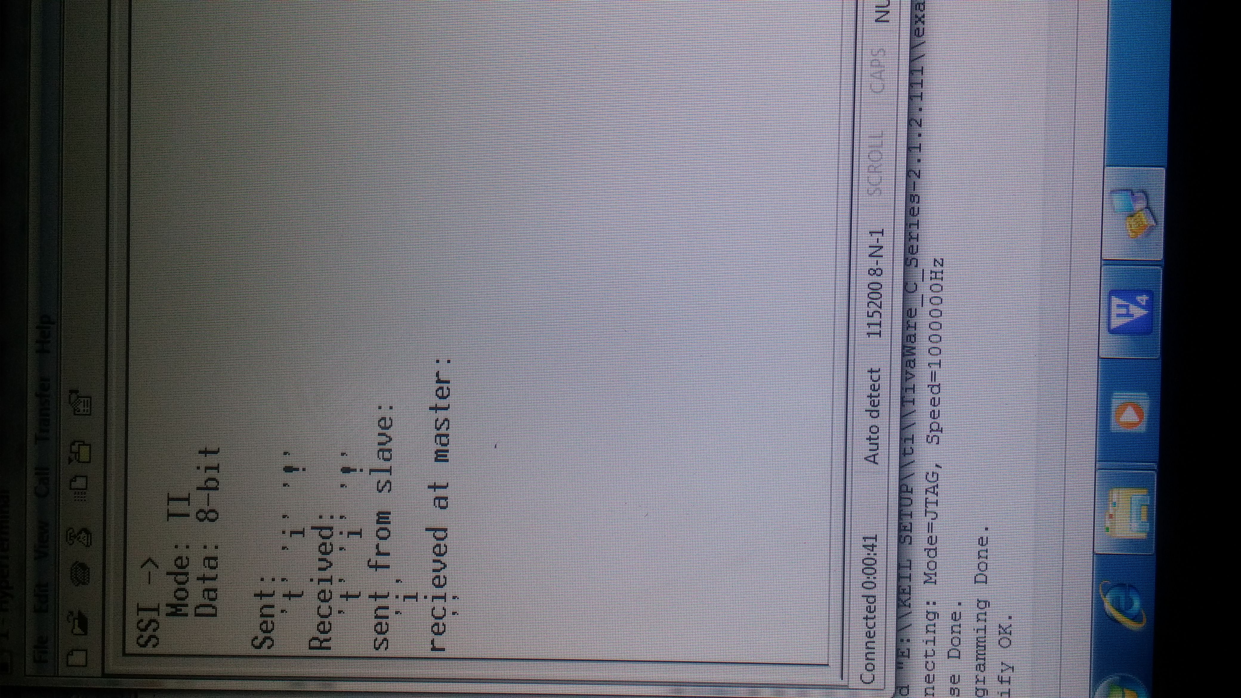
For ssi communication between two ports i am facing communication problem from slave to master end. I am using ssi0 and ssi2 where ssi0 is master and ssi2 is slave.From master to slave, communication is working fine but from slave to master my sent byte is not being received. in debug mode, i have seen that it shows 0x0000 instead of correct data. Please help.
Regards,
//*****************************************************************************
//
// ti_master.c - Example demonstrating how to configure SSI0 in TI master mode.
//
// Copyright (c) 2010-2015 Texas Instruments Incorporated. All rights reserved.
// Software License Agreement
//
// Redistribution and use in source and binary forms, with or without
// modification, are permitted provided that the following conditions
// are met:
//
// Redistributions of source code must retain the above copyright
// notice, this list of conditions and the following disclaimer.
//
// Redistributions in binary form must reproduce the above copyright
// notice, this list of conditions and the following disclaimer in the
// documentation and/or other materials provided with the
// distribution.
//
// Neither the name of Texas Instruments Incorporated nor the names of
// its contributors may be used to endorse or promote products derived
// from this software without specific prior written permission.
//
// THIS SOFTWARE IS PROVIDED BY THE COPYRIGHT HOLDERS AND CONTRIBUTORS
// "AS IS" AND ANY EXPRESS OR IMPLIED WARRANTIES, INCLUDING, BUT NOT
// LIMITED TO, THE IMPLIED WARRANTIES OF MERCHANTABILITY AND FITNESS FOR
// A PARTICULAR PURPOSE ARE DISCLAIMED. IN NO EVENT SHALL THE COPYRIGHT
// OWNER OR CONTRIBUTORS BE LIABLE FOR ANY DIRECT, INDIRECT, INCIDENTAL,
// SPECIAL, EXEMPLARY, OR CONSEQUENTIAL DAMAGES (INCLUDING, BUT NOT
// LIMITED TO, PROCUREMENT OF SUBSTITUTE GOODS OR SERVICES; LOSS OF USE,
// DATA, OR PROFITS; OR BUSINESS INTERRUPTION) HOWEVER CAUSED AND ON ANY
// THEORY OF LIABILITY, WHETHER IN CONTRACT, STRICT LIABILITY, OR TORT
// (INCLUDING NEGLIGENCE OR OTHERWISE) ARISING IN ANY WAY OUT OF THE USE
// OF THIS SOFTWARE, EVEN IF ADVISED OF THE POSSIBILITY OF SUCH DAMAGE.
//
// This is part of revision 2.1.2.111 of the Tiva Firmware Development Package.
//
//*****************************************************************************
#include <stdbool.h>
#include <stdint.h>
#include "inc/hw_memmap.h"
#include "driverlib/gpio.h"
#include "driverlib/pin_map.h"
#include "driverlib/ssi.h"
#include "driverlib/sysctl.h"
#include "driverlib/uart.h"
#include "utils/uartstdio.h"
#include "driverlib/rom.h"
//*****************************************************************************
//
//! \addtogroup ssi_examples_list
//! <h1>TI Master (ti_master)</h1>
//!
//! This example shows how to configure the SSI0 as TI Master. The code will
//! send three characters on the master Tx then poll the receive FIFO until
//! 3 characters are received on the master Rx.
//!
//! This example uses the following peripherals and I/O signals. You must
//! review these and change as needed for your own board:
//! - SSI0 peripheral
//! - GPIO Port A peripheral (for SSI0 pins)
//! - SSI0Clk - PA2
//! - SSI0Fss - PA3
//! - SSI0Rx - PA4
//! - SSI0Tx - PA5
//!
//! The following UART signals are configured only for displaying console
//! messages for this example. These are not required for operation of I2C0.
//! - UART0 peripheral
//! - GPIO Port A peripheral (for UART0 pins)
//! - UART0RX - PA0
//! - UART0TX - PA1
//!
//! This example uses the following interrupt handlers. To use this example
//! in your own application you must add these interrupt handlers to your
//! vector table.
//! - None.
//
//*****************************************************************************
//*****************************************************************************
//
// Number of bytes to send and receive.
//
//*****************************************************************************
#define NUM_SSI_DATA 3
uint32_t pui32DataTx[NUM_SSI_DATA];
uint32_t pui32DataRx[NUM_SSI_DATA];
uint32_t ui32Index;
//*****************************************************************************
//
// This function sets up UART0 to be used for a console to display information
// as the example is running.
//
//*****************************************************************************
//*****************************************************************************
//
// Configure SSI0 in master TI mode. This example will send out 3 bytes of
// data, then wait for 3 bytes of data to come in. This will all be done using
// the polling method.
//
//*****************************************************************************
void
Configure_UART0()
{
ROM_SysCtlPeripheralEnable(SYSCTL_PERIPH_UART0);
ROM_SysCtlPeripheralEnable(SYSCTL_PERIPH_GPIOA);
ROM_GPIOPinConfigure(GPIO_PA0_U0RX);
ROM_GPIOPinConfigure(GPIO_PA1_U0TX);
ROM_GPIOPinTypeUART(GPIO_PORTA_BASE, GPIO_PIN_0 | GPIO_PIN_1);
UARTClockSourceSet(UART0_BASE, UART_CLOCK_PIOSC);
UARTStdioConfig(0, 115200, 16000000);
// ROM_UARTConfigSetExpClk(UART0_BASE, ROM_SysCtlClockGet(), 115200,
// (UART_CONFIG_WLEN_8 | UART_CONFIG_STOP_ONE |
// UART_CONFIG_PAR_NONE));
//UARTEnable(UART0_BASE);
}
//************************************************************//
int
main(void)
{
ROM_FPULazyStackingEnable();
SysCtlClockSet(SYSCTL_SYSDIV_4 | SYSCTL_USE_PLL | SYSCTL_OSC_MAIN |
SYSCTL_XTAL_16MHZ);
Configure_UART0();
//
// Display the setup on the console.
//
UARTprintf("SSI ->\n");
UARTprintf(" Mode: TI\n");
UARTprintf(" Data: 8-bit\n\n");
//
// The SSI0 peripheral must be enabled for use.
//
SysCtlPeripheralEnable(SYSCTL_PERIPH_SSI0);
SysCtlPeripheralEnable(SYSCTL_PERIPH_SSI2);
//
// For this example SSI0 is used with PortA[5:2]. The actual port and
// pins used may be different on your part, consult the data sheet for
// more information. GPIO port A needs to be enabled so these pins can
// be used.
// TODO: change this to whichever GPIO port you are using.
//
SysCtlPeripheralEnable(SYSCTL_PERIPH_GPIOA);
SysCtlPeripheralEnable(SYSCTL_PERIPH_GPIOB);
//
// Configure the pin muxing for SSI0 functions on port A2, A3, A4, and A5.
// This step is not necessary if your part does not support pin muxing.
// TODO: change this to select the port/pin you are using.
//
GPIOPinConfigure(GPIO_PA2_SSI0CLK);
GPIOPinConfigure(GPIO_PA3_SSI0FSS);
GPIOPinConfigure(GPIO_PA4_SSI0RX);
GPIOPinConfigure(GPIO_PA5_SSI0TX);
//************************//
//*******Newly added for SSI2
GPIOPinConfigure(GPIO_PB4_SSI2CLK);
GPIOPinConfigure(GPIO_PB5_SSI2FSS);
GPIOPinConfigure(GPIO_PB6_SSI2RX);
GPIOPinConfigure(GPIO_PB7_SSI2TX);
//
// Configure the GPIO settings for the SSI pins. This function also gives
// control of these pins to the SSI hardware. Consult the data sheet to
// see which functions are allocated per pin.
// The pins are assigned as follows:
// PA5 - SSI0Tx
// PA4 - SSI0Rx
// PA3 - SSI0Fss
// PA2 - SSI0CLK
// TODO: change this to select the port/pin you are using.
//
GPIOPinTypeSSI(GPIO_PORTA_BASE, GPIO_PIN_5 | GPIO_PIN_4 | GPIO_PIN_3 |
GPIO_PIN_2);
GPIOPinTypeSSI(GPIO_PORTB_BASE, GPIO_PIN_7 | GPIO_PIN_6 | GPIO_PIN_5 |
GPIO_PIN_4); // newly added for ssi2
SSIConfigSetExpClk(SSI0_BASE, SysCtlClockGet(), SSI_FRF_MOTO_MODE_0, SSI_MODE_MASTER, 2000000, 8);
SSIConfigSetExpClk(SSI0_BASE, SysCtlClockGet(), SSI_FRF_MOTO_MODE_0, SSI_MODE_SLAVE, 2000000, 8);
//
// Configure and enable the SSI port for TI master mode. Use SSI0, system
// clock supply, master mode, 1MHz SSI frequency, and 8-bit data.
//
// Enable the SSI0 module.
//
SSIEnable(SSI0_BASE);
SSIEnable(SSI2_BASE);
//
// Read any residual data from the SSI port. This makes sure the receive
// FIFOs are empty, so we don't read any unwanted junk. This is done here
// because the TI SSI mode is full-duplex, which allows you to send and
// receive at the same time. The SSIDataGetNonBlocking function returns
// "true" when data was returned, and "false" when no data was returned.
// The "non-blocking" function checks if there is any data in the receive
// FIFO and does not "hang" if there isn't.
//
while(SSIDataGetNonBlocking(SSI0_BASE, &pui32DataRx[0]))
{
}
//
// Initialize the data to send.
//
pui32DataTx[0] = 't';
pui32DataTx[1] = 'i';
pui32DataTx[2] = '!';
//
// Display indication that the SSI is transmitting data.
//
UARTprintf("Sent:\n ");
//
 // Send 3 bytes of data.
 //
 for(ui32Index = 0; ui32Index < NUM_SSI_DATA; ui32Index++)
 {
	//
	// Display the data that SSI is transferring.
	//
	UARTprintf("'%c' ", pui32DataTx[ui32Index]);

	//
	// Send the data using the "blocking" put function. This function
	// will wait until there is room in the send FIFO before returning.
	// This allows you to assure that all the data you send makes it into
	// the send FIFO.
	//
	SSIDataPut(SSI0_BASE, pui32DataTx[ui32Index]);
 }
//
// Wait until SSI0 is done transferring all the data in the transmit FIFO.
//
while(SSIBusy(SSI2_BASE))
{
}
//
// Display indication that the SSI is receiving data.
//
UARTprintf("\nReceived:\n ");
while(SSIDataGetNonBlocking(SSI2_BASE, &pui32DataTx[0]))
{
}
//
// Receive 3 bytes of data.
//
for(ui32Index = 0; ui32Index < NUM_SSI_DATA; ui32Index++)
{
//
// Receive the data using the "blocking" Get function. This function
// will wait until there is data in the receive FIFO before returning.
//
SSIDataGetNonBlocking(SSI2_BASE, &pui32DataTx[ui32Index]);
//
// Since we are using 8-bit data, mask off the MSB.
//
pui32DataRx[ui32Index] &= 0x00FF;
//
// Display the data that SSI0 received.
//
UARTprintf("'%c' ", pui32DataTx[ui32Index]);
}
UARTprintf("\nsent from slave:\n ");
while(SSIDataGetNonBlocking(SSI0_BASE, &pui32DataTx[0]))
{
}
SSIDataPut(SSI2_BASE, pui32DataTx[1]);
UARTprintf("'%c' ", pui32DataTx[1]);
while(SSIBusy(SSI2_BASE))
{
}
pui32DataTx[1] = 'f';
UARTprintf("\nrecieved at master:\n ");
if(SSIDataGetNonBlocking(SSI0_BASE, &pui32DataTx[1]))
UARTprintf("'%c' ", pui32DataTx[1]);
else
UARTprintf("failed ");
//
// Return no errors
//
return(0);
}
//*********Output is as below***********//