This thread has been locked.
If you have a related question, please click the "Ask a related question" button in the top right corner. The newly created question will be automatically linked to this question.
Hi, I'm using an old revision of XDS100v3; this one doesn't have the "JUMPER ARM_JTAG_E".
So I'm trying to use the "TI's 20 pin JTAG connection" with my perf board that uses TM4C123GH6PMI.
I have created a JTAG connection like the above schematic.
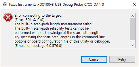
However, while using the CCS 7, I have received an error.
Is the above connection invalid; do I have to add a pull-up resistor to pin 4?
David,
Are you already following the XDS100v3 Users Manual provided by Olimex that details the JTAG connections for that emulator as well as the connection properties to be set in the CCS target configuration file?
Hello,
AartiG said:connection properties to be set in the CCS target configuration file?
you mean this?
I cannot find that "connection properties" on CCS 7.
<?xml version="1.0" encoding="UTF-8" standalone="no"?> <configurations XML_version="1.2" id="configurations_0"> <configuration XML_version="1.2" id="Texas Instruments XDS100v3 USB Debug Probe_0"> <instance XML_version="1.2" desc="Texas Instruments XDS100v3 USB Debug Probe_0" href="connections/TIXDS100v3_Dot7_Connection.xml" id="Texas Instruments XDS100v3 USB Debug Probe_0" xml="TIXDS100v3_Dot7_Connection.xml" xmlpath="connections"/> <connection XML_version="1.2" id="Texas Instruments XDS100v3 USB Debug Probe_0"> <instance XML_version="1.2" href="drivers/tixds100v2cs_dap.xml" id="drivers" xml="tixds100v2cs_dap.xml" xmlpath="drivers"/> <instance XML_version="1.2" href="drivers/tixds100v2cortexM.xml" id="drivers" xml="tixds100v2cortexM.xml" xmlpath="drivers"/> <platform XML_version="1.2" id="platform_0"> <instance XML_version="1.2" desc="Tiva TM4C123GH6PM_0" href="devices/tm4c123gh6pm.xml" id="Tiva TM4C123GH6PM_0" xml="tm4c123gh6pm.xml" xmlpath="devices"/> </platform> </connection> </configuration> </configurations>
This is my current configuration.
You mean I haven't followed the instruction fully, right?
Then how can I configure "nTRST boot-mod" or more with CCS 7?
Hi, thanks for your help, I have changed the configuration file like the picture below.
To be more specific, I use XDS100-v3 revision B.
However, the error 183 (SC_ERR_CTL_CBL_BREAK_FAR) was shown when I tried to debug or test the connection.
Start: Texas Instruments XDS100v3 USB Debug Probe_0] Execute the command: %ccs_base%/common/uscif/dbgjtag -f %boarddatafile% -rv -o -F inform,logfile=yes -S pathlength -S integrity [Result] -----[Print the board config pathname(s)]------------------------------------ C:\Users\ElliotS\AppData\Local\TEXASI~1\ CCS\ti\0\0\BrdDat\testBoard.dat -----[Print the reset-command software log-file]----------------------------- This utility has selected a 100- or 510-class product. This utility will load the adapter 'jioserdesusbv3.dll'. The library build date was 'Feb 13 2017'. The library build time was '16:06:25'. The library package version is '6.0.576.0'. The library component version is '35.35.0.0'. The controller does not use a programmable FPGA. An error occurred while hard opening the controller. -----[An error has occurred and this utility has aborted]-------------------- This error is generated by TI's USCIF driver or utilities. The value is '-183' (0xffffff49). The title is 'SC_ERR_CTL_CBL_BREAK_FAR'. The explanation is: The controller has detected a cable break far-from itself. The user must connect the cable/pod to the target. [End: Texas Instruments XDS100v3 USB Debug Probe_0]
As you remember, my perf board connection is like this.
The VDDC pins (25 & 56) show 1.397 V on the multimeter.
Then is this related to wiring problems or is the MCU malfunctioning?
Just in case, I have ordered extra TM4C MCUs to test this.
The TCK signal is not shown as connected on the "TI JTAG 20" connector. TCK should be connected to pin 11 on the "TI JTAG 20" connector.David__ said:As you remember, my perf board connection is like this.
Some other comments:
1) The application report Using TM4C12x Devices Over JTAG Interface recommends pull-ups / pull-downs on the JTAG signals to drive the signals to an inactive state when no debugger is connected.
2) The TM4C123 devices don't support Adaptive Clocking, so the "The Debug Probe 1149.1 Frequency" in the Connection Properties should be set to a Fixed rather than Adaptive value.