This thread has been locked.

If you have a related question, please click the "Ask a related question" button in the top right corner. The newly created question will be automatically linked to this question.

EK-TM4C123GXL: Can I power a 5V (LCD) peripheral with this launch pad?

Part Number: EK-TM4C123GXL
Other Parts Discussed in Thread: TM4C123GH6PZ

Hello,

I was browsing amazon for my current project using the EK-TM4C123GXL launchpad for a LCD, turns out the LCD I purchased actually runs off 5V (even though in the dang title it claims 3.3V):

I picked up a: LCD1602 3.3V Blue Backlight 16 Characters 2 Lines 1602 LCD LCM Display Module TN/STN Compatible With Arduino by Atomic Market

My questions is will I be able to power this 5V peripheral with the EK-TM4C123GXL? It's possible that the LCD will work with a 3.3V, but would like to have a backup plan if that doesn't work. Also can anyone recommend any tutorials for using this LCD (based on HD44780 equivalent LCD controller) with this launchpad?

Thanks

  • You may find multiple (past) posts - dealing w/such character Lcd Modules - via the forum's Search Box - atop the forum page.

    3V3 output from your MCU is (near) the lower threshold (3V5) for the Lcd's "logic high."     May/may not work.     (how satisfying that)
    A sure solution would see you employing an 8 bit, digital level shifter - which translates 3V In to 5V out - and vice versa.     Note that during a display "read" the Lcd's bus will output @ 5V levels to your MCU - which may cause damage - in time.      (again - the level shifter chip - to the rescue)      Digikey should locate a suitable, 8 channel, level shifter - via (their) Search Box.     (again - atop their page)

    Dawns that beyond the 8 bit data bus - you should equally "up convert" the 2 control bits: RS & E.      Thus 10 bits of 3V <-> 5V are required.    (assumes you never read, tie R/W to Gnd.)

  • cb1_mobile said:
    during a display "read" the Lcd's bus will output @ 5V levels to your MCU - which may cause damage

    Just to be "precious" here: the specific part mentioned, TM4C123, accepts 5V logic signals - hence that minor issue won't be a problem.

    When you consider labor as well, it will be cheaper to buy a new LCD that accepts 3V3 than to put together the whole level shifting for one project. But if it is a project that involves some quantity, and you have a good enough reason to stick to the 5V LCD, then another decision to be made is while it is worth to use only 4 bits of data as opposed to 8 bits, so that the level shifter can be a smaller part.

    Still, look again at the LCD specs. Maybe it only needs 5V POWER, but it can still take 3V3 LOGIC. That is quite common, we use a popular 2x20 display that behaves like that.

    As to effectively POWER the LCD with this launchpad: LCD's require very little current, and the onboard 5V circuit of the launchpad will be good enough to power the display - provided that the backlight is NOT used. But it is not wise to rely on the launchpad power circuits for external devices, unless one is sure of the required power - in the end, you have to evaluate the current required by your peripheral, against what is available from the onboard 5V switcher.

    Bruno

  • Bruno Saraiva said:
    TM4C123, accepts 5V logic signals

    Devil word here may be, "accepts."      In the case of our poster - the Lcd outputs (only) while the "E" signal is active & R/W is @ logic high - thus the invasion of 5V @ the MCU is brief.     (assumes E properly toggles)

    Back to "accepts" - does the MCU spec define the "duration" of such 5V introduction?     MCU's ESD diode must absorb that "over-voltage" - and if "no" series resistance is present - it IS possible that in time - the ESD diode(s) may be negatively impacted.      From my tour @ another semi "giant" - these ESD diodes are intended as "transient absorbers" - forcing them to "long-term" voltage clamping is outside "best practice."

    A "better" word may be, "Tolerates" - which alerts that such practice is less than ideal...

  • cb1_mobile said:
    does the MCU spec define the "duration" of such 5V introduction?

    Yes, it does. The duration is FOREVER.

    It is a TM4123. The world ACCEPTS is correct here, cb1. You can apply 5V into this MCU GPIO's. To be more precise, on a TM4C123GH6PZ the exceptions are PJ0, PJ1, PB0 and PB1.

  • And your proof for the claim, "Forever" (with no series resistors) - is found where?         (your unique, "brief test/observation" - cannot serve as such "proof.")

    You may note that when set as "Output" the number of GPIOs employed on that "side" (quadrant) of the MCU - is likely to be limited.     (especially when GPIOs output raised currents)      Similarly - if multiple GPIO inputs are "inflicted w/5V" - extra dissipation occurs w/in the MCU (needlessly) - and your "Forever claim" (never past seen) may prove destructive!

    Are you in denial that the central purpose of (standard) ESD input diodes is transient suppression - rather than "forever accepting - over-voltage abuse?"  

    Classic MCU use has long stressed the practice of NOT employing the MCU as a, "Beast of burden."       Such excess voltage should be handled externally - via simple voltage divider(s) - to provide the least stress to the MCU.  

  • cb1_mobile said:
    And your proof for the claim, "Forever" (with no series resistors) - is found where?

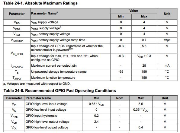
    This is what the datasheet says:

    I understand that 5V is not over-voltage for such devices, and that there would still be room for another 500mV. It is different from what TM4C129x devices can take.

    One of our boards does have a 5V signal directly into the MCU and fortunately that has never been an issue.

  • I'd read it that way as well Bruno, although I'd still put a resistor in series rather than stress the micro. Resistors are cheap and small.

    Robert
  • Indeed - best practice is as Bruno noted earlier - "Choose a 3V3 Powered & Operated Lcd."
    Series resistors reduce the (unnecessary dissipation) forced upon the MCU - which when arriving upon (multiple) inputs - HAS been known to stress the MCU.

    The spec does not detail the "long term presentation of 5V - it notes that the MCU can tolerate such (even when MCU is powered down) but that fact alone does not establish "duration of such voltage introduction." And any test by you/Robert/I is not sufficient to provide "proof."

    Note that there (usually) IS a downside to adding such "5V tolerance" - most always the frequency response of those MCU pins will be reduced. (often due to the added capacitance introduced by the "protection" components)