Part Number: TM4C123GH6PM
Tool/software: Code Composer Studio
Hi,
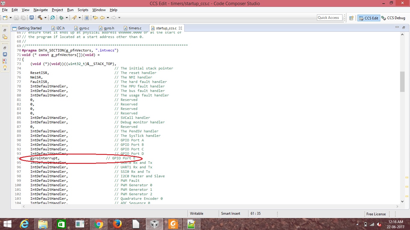
Once again thanks for all the people in the community for their support. I am facing a problem in the GPIO interrupt. I am working with the gyroscope sensor and i configured using I2C, in that i try to enable the GPIO interrupt for the reading of raw sensor data when the watermark interrupt occured then i am reading the sensor value. Here i attached the code which i am using for the interrupt
#include <stdbool.h>
#include <stdint.h>
#include <string.h>
#include <stdio.h>
#include <math.h>
#include "inc/hw_i2c.h"
#include "inc/hw_ints.h"
#include "inc/hw_memmap.h"
#include "inc/hw_types.h"
#include "driverlib/gpio.h"
#include "driverlib/fpu.h"
#include "driverlib/i2c.h"
#include "driverlib/debug.h"
#include "driverlib/pin_map.h"
#include "driverlib/sysctl.h"
#include "driverlib/rom.h"
#include "driverlib/uart.h"
#include "utils/uartstdio.h"
#include "driverlib/interrupt.h"
#include "gyro.h"


struct Sensor_Data
{
	int16_t Gyro_x_raw;
	int16_t Gyro_y_raw;
	int16_t Gyro_z_raw;
};

struct Sensor_Data Sensor_Value = {
									0,0,0                                              //GYROSCOPE X,Y,Z
								  };

static unsigned char fifolevel = 0;

static unsigned char data = 0;

static unsigned int flags = 0;

void
InitConsole(void)
{
    //
    // Enable GPIO port A which is used for UART0 pins.
    // TODO: change this to whichever GPIO port you are using.
    //
    SysCtlPeripheralEnable(SYSCTL_PERIPH_GPIOA);

    //
    // Configure the pin muxing for UART0 functions on port A0 and A1.
    // This step is not necessary if your part does not support pin muxing.
    // TODO: change this to select the port/pin you are using.
    //
    GPIOPinConfigure(GPIO_PA0_U0RX);
    GPIOPinConfigure(GPIO_PA1_U0TX);

    //
    // Enable UART0 so that we can configure the clock.
    //
    SysCtlPeripheralEnable(SYSCTL_PERIPH_UART0);

    //
    // Use the internal 16MHz oscillator as the UART clock source.
    //
    UARTClockSourceSet(UART0_BASE, UART_CLOCK_PIOSC);

    //
    // Select the alternate (UART) function for these pins.
    // TODO: change this to select the port/pin you are using.
    //
    GPIOPinTypeUART(GPIO_PORTA_BASE, GPIO_PIN_0 | GPIO_PIN_1);

    //
    // Initialize the UART for console I/O.
    //
    UARTStdioConfig(0, 115200, 16000000);
}


void i2cController2Intialise(void)
{

#if defined(TARGET_IS_TM4C129_RA0) ||                                         \
    defined(TARGET_IS_TM4C129_RA1) ||                                         \
    defined(TARGET_IS_TM4C129_RA2)
    ui32SysClock = SysCtlClockFreqSet((SYSCTL_XTAL_25MHZ |
                                       SYSCTL_OSC_MAIN |
                                       SYSCTL_USE_OSC), 25000000);
#else
      SysCtlClockSet(SYSCTL_SYSDIV_4 | SYSCTL_USE_PLL | SYSCTL_OSC_MAIN |          //System clock = 50MHZ
    		SYSCTL_XTAL_25MHZ);
    /*SysCtlClockSet(SYSCTL_SYSDIV_1 | SYSCTL_USE_OSC | SYSCTL_OSC_MAIN |
    		SYSCTL_XTAL_16MHZ);*/
#endif

   // The I2C2 peripheral must be enabled before use.

    //
    SysCtlPeripheralEnable(SYSCTL_PERIPH_I2C2);

    //
    // For this example I2C2 is used with PortB[3:2].  The actual port and
    // pins used may be different on your part, consult the data sheet for
    // more information.  GPIO port B needs to be enabled so these pins can
    // be used.
    // TODO: change this to whichever GPIO port you are using.
    //
    SysCtlPeripheralEnable(SYSCTL_PERIPH_GPIOE);

    //
    // Configure the pin muxing for I2C2 functions on port B2 and B3.
    // This step is not necessary if your part does not support pin muxing.
    // TODO: change this to select the port/pin you are using.
    //
    GPIOPinConfigure(GPIO_PE4_I2C2SCL);
    GPIOPinConfigure(GPIO_PE5_I2C2SDA);

    //
    // Select the I2C function for these pins.  This function will also
    // configure the GPIO pins pins for I2C operation, setting them to
    // open-drain operation with weak pull-ups.  Consult the data sheet
    // to see which functions are allocated per pin.
    // TODO: change this to select the port/pin you are using.
    //
    GPIOPinTypeI2CSCL(GPIO_PORTE_BASE, GPIO_PIN_4);
    GPIOPinTypeI2C(GPIO_PORTE_BASE, GPIO_PIN_5);

    //
    // Enable and initialize the I2C2 master module.  Use the system clock for
    // the I2C2 module.  The last parameter sets the I2C data transfer rate.
    // If false the data rate is set to 100kbps and if true the data rate will
    // be set to 400kbps.  For this example we will use a data rate of 100kbps.
    //
#if defined(TARGET_IS_TM4C129_RA0) ||                                         \
    defined(TARGET_IS_TM4C129_RA1) ||                                         \
    defined(TARGET_IS_TM4C129_RA2)
    I2CMasterInitExpClk(I2C2_BASE, ui32SysClock, false);
#else
    I2CMasterInitExpClk(I2C2_BASE,SysCtlClockGet(), true);                     //system clock - 50mhz,TPR - 0x06
#endif

}

void gyroInterrupt( void )
{
	L3G4200D_Register_Write( SLAVE_ADDRESS_L3G4200D, L3G4200D_FIFO_CTRL_REG, 0x4A );             //FIFO control reg : stream mode and WTM-10

	L3G4200D_Register_Read( SLAVE_ADDRESS_L3G4200D, L3G4200D_FIFO_SRC_REG, &fifolevel);       //FIFO status reg

	UARTprintf("Interrupt occuring\n");

	if( 0x80 & fifolevel )
	{
		flags = 1;
	}

}


int main( void )
{
	unsigned char deviceID = 0;

	short int i = 0;

	ROM_FPULazyStackingEnable();

	i2cController2Intialise();

	InitConsole();

	//ROM_GPIOPinTypeGPIOOutput( GPIO_PORTE_BASE, GPIO_PIN_2 );

	ROM_GPIOIntTypeSet( GPIO_PORTE_BASE, GPIO_PIN_2, GPIO_BOTH_EDGES );

	ROM_IntEnable( INT_GPIOE );

	ROM_IntMasterEnable();

	L3G4200D_Register_Read( SLAVE_ADDRESS_L3G4200D, L3G4200D_WHO_AM_I, &deviceID );

	UARTprintf("deviceID : 0x%x\n",deviceID);

	L3G4200D_Register_Write( SLAVE_ADDRESS_L3G4200D, L3G4200D_CTRL_REG1, 0x3F );                 //Control register 1 100hz and normal,all axis enabled

	L3G4200D_Register_Write( SLAVE_ADDRESS_L3G4200D, L3G4200D_CTRL_REG3, 0x07 );                 //Control reg 3 : WTm,empty,overrun enabled

	L3G4200D_Register_Write( SLAVE_ADDRESS_L3G4200D, L3G4200D_CTRL_REG4, 0x80);                  //BDU 1 and 250dps

	L3G4200D_Register_Write( SLAVE_ADDRESS_L3G4200D, L3G4200D_CTRL_REG5, 0x5F);                  //FIFO enabled and Hpen-1,INT-11,OUT-11

	//L3G4200D_Register_Write( SLAVE_ADDRESS_L3G4200D, L3G4200D_FIFO_CTRL_REG, 0x4A );             //FIFO control reg : stream mode and WTM-10

	while( 1 )
	{

		//UARTprintf("FIFOlevel : 0x%x\n",fifolevel);
#if 1
		if( 1 == flags )																	  // Checking for the watermark interrupt
		{
			data = fifolevel & 0x1F;

			UARTprintf("FIFOlevel : 0x%x\n",fifolevel);

			for( i = 0; i < data; i = i + 1 )
			{
				Read_L3G4200D_RawData( &Sensor_Value.Gyro_x_raw, &Sensor_Value.Gyro_y_raw, &Sensor_Value.Gyro_z_raw );

				UARTprintf("%d,%d,%d\n",Sensor_Value.Gyro_x_raw,Sensor_Value.Gyro_y_raw,Sensor_Value.Gyro_z_raw);
			}

			L3G4200D_Register_Write( SLAVE_ADDRESS_L3G4200D, L3G4200D_FIFO_CTRL_REG, 0x0A );	  // FIFO is changed to bypass mode

			flags = 0;
		}
#endif
	}

}
no interrupt was occuring it not going the gyroInterrupt(); function.Is there any mistake in my code,if there please correct me and provide me the solution.