This thread has been locked.

If you have a related question, please click the "Ask a related question" button in the top right corner. The newly created question will be automatically linked to this question.

TM4C123GH6PM: CAN Bit time calculation.

Part Number: TM4C123GH6PM

Hello TM4C forum,

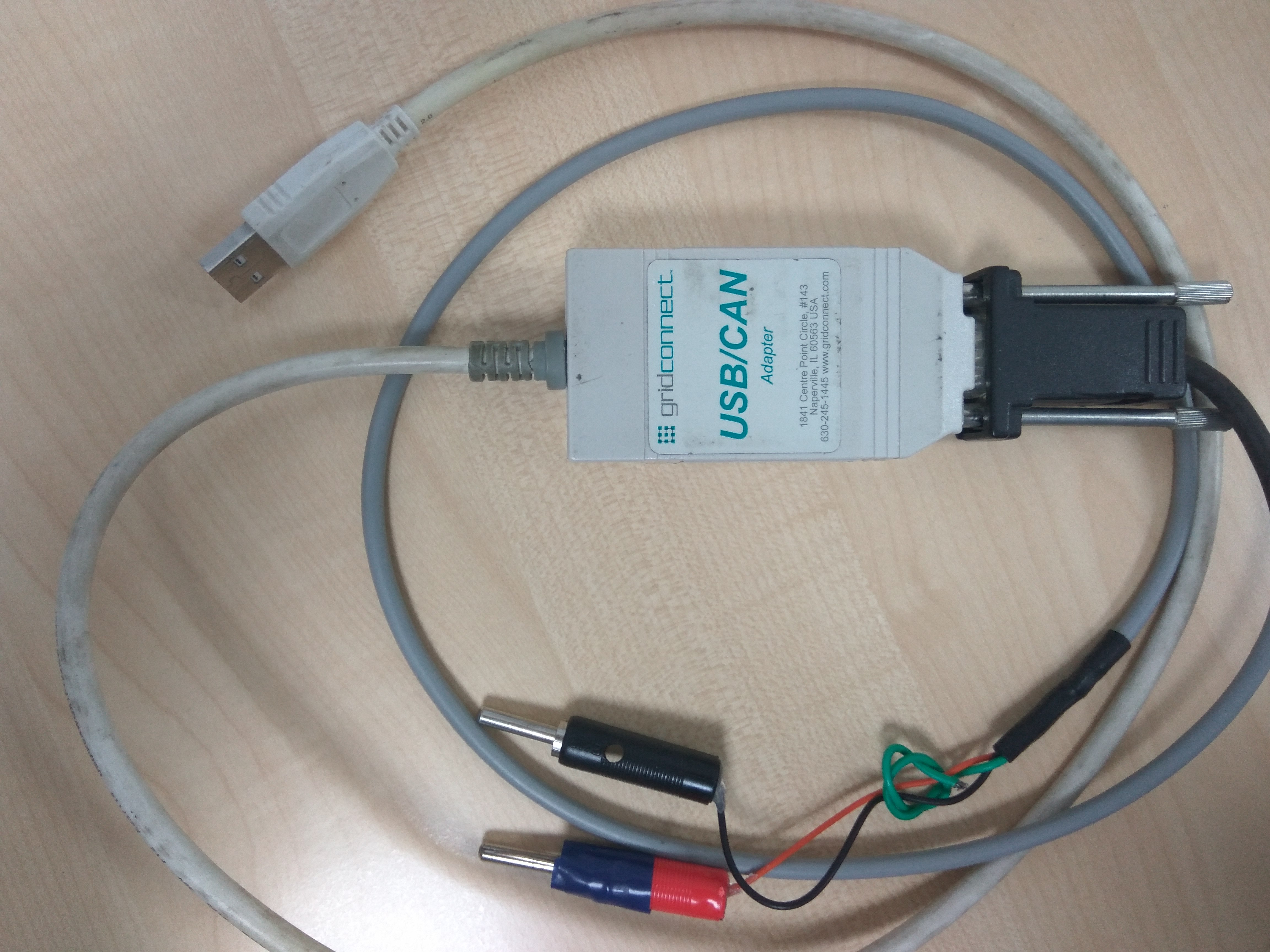
Currently i am working on TM4C123GH6PM microcontroller for CAN application. I am sending/receiving the data from/to PCAN.

I have used CANBitRateSet() driver function for setting the baud rate with 50MHz clock. It was observed that, when the baud rate is configured for 100k,125k,250k and 500kbps, it works smoothly. But when the baud rate is increased to 800k or 1Mbps, the PCAN displays BUSHEAVY/BUSOFF conditions for 50MHz sysclk.

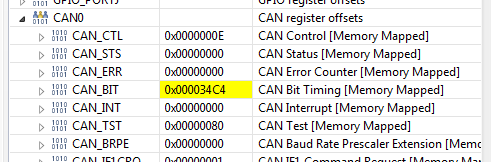
Then instead of CANBitRateSet() function, i tried by using CANBitTimingSet() for setting the bit rate which inturn uses tCANBitClkParms structure as shown below. The CAN clock was set to 50MHz. In this configuration also, it was observed that, when bit rate is above 500kbps the PCAN displays BUSHEAVY/BUSOFF conditions.

tCANBitClkParms CANBitClkSettings[] =
{
{16, 8, 4, 20},     // CANBAUD_100K ok at 50MHz clock.
{13, 2, 4, 25},     // CANBAUD_125K ok at 50MHz clock.
{6, 1, 2, 25} ,        // CANBAUD_250K ok at 50MHz clock.
{16, 3, 2, 5},         // CANBAUD_500K ok at 50MHz clock.
{8, 1, 1, 5}          // CANBAUD_1M ok at 50MHz clock.
};
The tCANBitClkParms  data structure contains the values for SyncPropPhase1, Phase2, SJW, BRP used for calculating bit rate. 

typedef struct
{

uint32_t ui32SyncPropPhase1Seg;

uint32_t ui32Phase2Seg;

uint32_t ui32SJW;

uint32_t ui32QuantumPrescaler;

}
tCANBitClkParms;

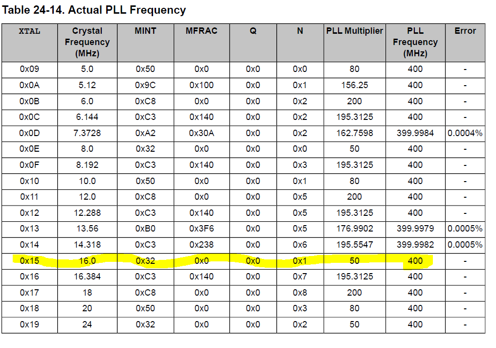
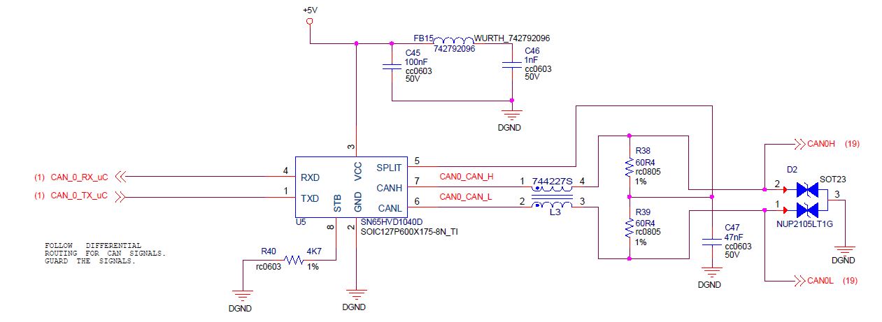
I am using SN65HVD1040D CAN transceiver and using 8MHz XTAL.

Please anyone help me out, how these values shown in the above data structure were calculated or the parameters considered for getting these values to achieve the respective bit rate.

Thanks in advance.

  • CAN bit timing is, as I recall, explained in the manual. More usefully there are a number of explanatory tutorials around the web.

    That being said I expect your problem is likely cabling, termination or transceivers rather than bit rate settings.

    Robert
  • HI Robert Adsett,

    I have tried with Baud rates 100k, 125k, 250k and 500k. It is working smoothly. And i have checked at CAN Transceiver end, i am getting data properly. But if the baud rate is 1Mbps using CANBitRateSet() library function, getting BUS OFF/BUSY in PCAN.

  • That is essentially just a repeat of your original post. Not sure how it answers your question but if you are satisfied....

    Robert

  • *** Corrected ***

    I have reliable CAN communication at 1M baud with 50MHz system clock using:

        // 50MHz from 16MHz crystal
        SysCtlClockSet(SYSCTL_SYSDIV_4 | SYSCTL_USE_PLL | SYSCTL_OSC_MAIN |
                       SYSCTL_XTAL_16MHZ);
    

        CANBitRateSet(CAN0_BASE, SysCtlClockGet(), 1000000);
    

  • The CAN0 registers are set as shown: *** Corrected ***

  • Bob Crosby said:
    // 50MHz from 16MHz crystal

    SysCtlClockSet(SYSCTL_SYSDIV_8 | SYSCTL_USE_PLL | SYSCTL_OSC_MAIN | SYSCTL_XTAL_16MHZ);

    Might that  "50MHz from 16MHz crystal"  result (instead) from, "SYSCTL_SYSDIV_4"?

    TM4C123 runs PLL @ 200MHz (iirc) - thus the divide is 4.

  • CB1, as always thank you for double checking me. I pulled this table from page 1374 of the data sheet which shows the PLL at 400Mhz. The CAN worked correctly at 1MBaud (connected to a NI USB CAN module) which implies that I really was operating at 50MHz using SYSCTL_SYSDIV_8.

  • CB1, I should never question your corrections. You are correct. It should be SYSCTL_SYSDIV_4 since the PLL is divided by 2 before it goes to the system clock divider. I was running at 25MHz, and the software correctly calculated the settings for a CAN baud rate of 1MBaud based on 25MHz system clock.
  • Bob Crosby said:
    CB1, I should never question your corrections.

    Bob - we both realize that - on occasion - even a blind squirrel blunders upon a walnut.      To be "fair" - multiple times I have "Liked" your posts (not just "corrected") - thus there IS a balance.      (although that "like" favor appears not to have been returned...)

    Would that gf - unruly sailing crüe - and crack staff  (all) adopt that,  "aversion to question."       (Not a chance...)

  • Hi Bob Crosby,

    I am using 50MHz from 8MHz crystel.

    ROM_SysCtlClockSet(SYSCTL_SYSDIV_4 | SYSCTL_USE_PLL | SYSCTL_OSC_MAIN | SYSCTL_XTAL_8MHZ);

    and using CANBitTimingSet() library function for Baud Rate.

    #define CANBAUD_100K 0
    #define CANBAUD_125K 1
    #define CANBAUD_250K 2
    #define CANBAUD_500K 3
    #define CANBAUD_1M    4

    CANBitTimingSet(CAN1_BASE,&CANBitClkSettings[CANBAUD_500K]);

    tCANBitClkParms CANBitClkSettings[] =
    {
    {16, 8, 4, 20},    // CANBAUD_100K ok at 50MHz clock.
    {13, 2, 4, 25},    // CANBAUD_125K ok at 50MHz clock.
    {6, 1, 2, 25} ,     // CANBAUD_250K ok at 50MHz clock.
    {16, 3, 2, 5},      // CANBAUD_500K ok at 50MHz clock.
    {8, 1, 1, 5}         // CANBAUD_1M ok at 50MHz clock.
    };

    Could you please help me out, what are the CAN bit timing parameter values to achieve 100k, 125k, 250k, 500k, 800k and 1mbps baud rate for 80MHz system clock from 8MHz crystal. 

    Thanks & Regards

    Suman 

  • Hi,

    In my application, i am using 80MHz from 8Mhz crystal.
    and CANBitRateSet(CAN1_BASE, SysCtlClockGet(),Baudrate);
    Here, for baud rates 100k, 125k, 250k, 500k, getting data from CAN transceiver(SN65HVD1040D) and also i can see the data in PCAN with those baud rates.
    But, if baud rate is 800k or 1 mbps, didn't get data from CAN Transceiver and PCAN is showing BUSHEAVY.

    So, Instead of using CANBitRateSet() library function, I decided to use CANBitTimingSet() library function.
    Please help me out, what are the CAN bit timing parameter values need to pass through the CANBitTimingSet() to get 100k, 125k, 250k, 500k, 800k and 1Mbps Baud Rate for 80MHz system clock from 8MHz crystal. In data sheet of CAN Transceiver(SN65HVD1040D) is telling that, it supports upto 1 mbps baud rate.

    Could you please calculate the CAN Bit timing parameters at 80MHz system clock for above mention baud rates.

    As discussed in earlier post,
    In stellariware micro controller, I have tried with 50MHz from 8MHz crystal, and using CANBitTimingSet() library with below mentioned CAN Bit clock parameter values, it is working smoothly for 100k, 125k, 250k, 500k and 1Mbps baud rate. I am able see the data in PCAN also.

    tCANBitClkParms CANBitClkSettings[] =
    {
    {16, 8, 4, 20}, // CANBAUD_100K ok at 50MHz clock.
    {13, 2, 4, 25}, // CANBAUD_125K ok at 50MHz clock.
    {6, 1, 2, 25} , // CANBAUD_250K ok at 50MHz clock.
    {16, 3, 2, 5}, // CANBAUD_500K ok at 50MHz clock.
    {8, 1, 1, 5} // CANBAUD_1M ok at 50MHz clock.
    };
    Here,
    bit rate = CAN Clock / ((ui32SyncPropPhase1Seg + ui32Phase2Seg + 1) * (ui32QuantumPrescaler)) ;
    Based on above CAN bit clock setting parameter values and 50MHz from 8MHz crystel, may i know, what is the value of Propagation segment, Phase 1 segment, phase 2 segment value and total number of quantum (n) value.
  • Suman Soora said:
    In my application, i am using 80MHz from 8Mhz crystal.
    and CANBitRateSet(CAN1_BASE, SysCtlClockGet(),Baudrate);
    Here, for baud rates 100k, 125k, 250k, 500k, getting data from CAN transceiver(SN65HVD1040D) and also i can see the data in PCAN with those baud rates.
    But, if baud rate is 800k or 1 mbps, didn't get data from CAN Transceiver and PCAN is showing BUSHEAVY.

    My original suggestion/question still stands. And I will add to those, the length of the cable.

    You have not provided any reasoning for thinking the original parameters should be modified.

    Robert

  • Robert Adsett said:
    Suman Soora
    In my application, i am using 80MHz from 8Mhz crystal.
    and CANBitRateSet(CAN1_BASE, SysCtlClockGet(),Baudrate);
    Here, for baud rates 100k, 125k, 250k, 500k, getting data from CAN transceiver(SN65HVD1040D) and also i can see the data in PCAN with those baud rates.
    But, if baud rate is 800k or 1 mbps, didn't get data from CAN Transceiver and PCAN is showing BUSHEAVY.

    My original suggestion/question still stands. And I will add to those, the length of the cable.

    Let me be a little more explicit

    1. What is your transceiver?
    2. What are you using for a cable?
    3. How long is your cable?
    4. How are you terminating the bus?

    Robert

  • His transceiver was listed, "CAN transceiver(SN65HVD1040D)."

    All other of your questions (and mine) hold.

    In addition - any Freq. error at the (other) end - if in the opposite direction of MCU's error - proves additive - thus the (other) end demands attention too!

    Poster's continued "Cut/Pastes" prove not so fruitful - instead real measurements - and direct response to probings - best resolve...

    As always - test upon MULTIPLE BOARDS (never just one) avoids "helper abuse" (surely a high poster concern) in diagnosing dreaded, "Single Board Anomalies."

  • There are several ways to achieve those timings. To make them the same as you have with the 50MHz clock, simply change the pre-scale by 8/5.

    	tCANBitClkParms CANBitClkSettings[] =
    	{
    		{16, 8, 4, 32},    // CANBAUD_100K ok at 80MHz clock.
    		{13, 2, 4, 40},    // CANBAUD_125K ok at 80MHz clock.
    		{6, 1, 2, 40} ,    // CANBAUD_250K ok at 80MHz clock.
    		{16, 3, 2, 8},     // CANBAUD_500K ok at 80MHz clock.
    		{8, 1, 1, 8}       // CANBAUD_1M ok at 80MHz clock.
    	};
    

  • Hi,

    In my application, i am using 80MHz from 8Mhz crystal.
    and CANBitRateSet(CAN1_BASE, SysCtlClockGet(),Baudrate);
    Here, for baud rates 100k, 125k, 250k, 500k, getting data from CAN transceiver(SN65HVD1040D) and also i can see the data in PCAN with those baud rates.
    But, if baud rate is 800k or 1 mbps, didn't get data from CAN Transceiver and PCAN is showing BUSHEAVY.

    So, Instead of using CANBitRateSet() library function, I decided to use CANBitTimingSet() library function.
    Please help me out, what are the CAN bit timing parameter values need to pass through the CANBitTimingSet() to get 100k, 125k, 250k, 500k, 800k and 1Mbps Baud Rate for 80MHz system clock from 8MHz crystal. In data sheet of CAN Transceiver(SN65HVD1040D) is telling that, it supports upto 1 mbps baud rate.

    Could you please calculate the CAN Bit timing parameters at 80MHz system clock for above mention baud rates.

    As discussed in earlier post,
    In stellariware micro controller, I have tried with 50MHz from 8MHz crystal, and using CANBitTimingSet() library with below mentioned CAN Bit clock parameter values, it is working smoothly for 100k, 125k, 250k, 500k and 1Mbps baud rate. I am able see the data in PCAN also.

    tCANBitClkParms CANBitClkSettings[] =
    {
    {16, 8, 4, 20}, // CANBAUD_100K ok at 50MHz clock.
    {13, 2, 4, 25}, // CANBAUD_125K ok at 50MHz clock.
    {6, 1, 2, 25} , // CANBAUD_250K ok at 50MHz clock.
    {16, 3, 2, 5}, // CANBAUD_500K ok at 50MHz clock.
    {8, 1, 1, 5} // CANBAUD_1M ok at 50MHz clock.
    };
    Here,
    bit rate = CAN Clock / ((ui32SyncPropPhase1Seg + ui32Phase2Seg + 1) * (ui32QuantumPrescaler)) ;
    Based on above CAN bit clock setting parameter values and 50MHz from 8MHz crystel, may i know, what is the value of Propagation segment, Phase 1 segment, phase 2 segment value and total number of quantum (n) value.

  • HI Bob Crosby,

    Thank you for replay. I will try with this values.

    Thanks and Regards
    Suman Soora
  • Hi

    I am using gridconnect USB/CAN adapter and its length is about 1 meter , connected between hardware and PC.
    And i will try with another board.

    Thanks and Regards
    Suman Soora
  • Dear Robert,

    This is how the hardware interface is:

  • Manuraj Nambayil said:
    This is how the hardware interface is:

    There is nothing after this point.

    Robert

  • Suman Soora said:

    I am using gridconnect USB/CAN adapter and its length is about 1 meter , connected between hardware and PC.

    One metre is good, but that still leaves the questions about termination and cable.

    Robert

  • This is how the hardware interface is:

    Look (very) fast folks!

    ("some" effort (review) required when posting...)       Note that the "empty" hardware interface has (like "LIKE") gone AWOL!      (yet has been (twice now) preserved...)

  • Thank you for updating the hardware interface

  • Good Manuraj,

    That looks good. What about the other end and what about the cable?

    Robert

  • Hi Robert,

    We are using grid connect USB/CAN Adapter device and length of the cable is about 1 meter. And we have been using the same set-up for the past 5 years.

    Refer the below snapshot for device and cable.

  • Your CAN interface schematic is quite good - yet the CAN Xcvr is powered from 5V - not 3V3. Might that alone account for the "fall-off" you note at the highest (i.e. most demanding) CAN Data Rates? (Your MCU outputs 3V3 - which may prove "marginal" for a 5V powered IC - especially at extreme data rates!)

    3V3 CAN Xcvrs ARE available - and are likely to "fit" your existing pcb footprint...

  • Ok, cb1 caught the power supply issue on the transceiver. This photo shows two others. First there is no evidence of a terminator, that's even more important on a MBps bus. Second that looks like only a portion of the wiring which then splits out in some unknown fashion before connecting to your board.

    Robert
  • One other thing. I can't tell for sure from that photo but that cable looks suspicious as well. What is the impedance of the twisted pair? Does it even have a twisted pair?

    Robert
  • Do you have scope shots of the CAN bus? It would be interesting to measure the single bit times of the TM4C compared to the single bit times from the GRIDCONNECT.
  • Hi Bob Crosby,

    I have attached the oscilloscope snaps for CAN message