This thread has been locked.

If you have a related question, please click the "Ask a related question" button in the top right corner. The newly created question will be automatically linked to this question.

CCS/TM4C129XNCZAD: Bricked micro Error -1170 @ 0x0 Unable to access the DAP

Part Number: TM4C129XNCZAD
Other Parts Discussed in Thread: UNIFLASH

Tool/software: Code Composer Studio

How can I erase my microcontroller? I believe I have locked up my device. And the bad program code may be preventing the JTAG communication.

I am using an XDS100 V2.

The complete error message is:

Error connecting to the target:
(Error -1170 @ 0x0)
Unable to access the DAP. Reset the device, and retry the operation. If error persists, confirm configuration, power-cycle the board, and/or try more reliable JTAG settings (e.g. lower TCLK).
(Emulation package 6.0.628.1)

The following line of code was added and ran during a debug session. The micro cannot be debugged afterwords:

clkFreq = SysCtlClockFreqSet(SYSCTL_USE_PLL | SYSCTL_XTAL_25MHZ | SYSCTL_OSC_MAIN, 50000000);

I have recreated this issue on a second device. Both devices successfully launched a debug session, and failed to connect afterwords.

The subsequent code blinked an LED on the board. The LED blinking code never runs. It ran with the following line of code:

SysCtlClockSet(SYSCTL_SYSDIV_5|SYSCTL_USE_PLL|SYSCTL_XTAL_16MHZ|SYSCTL_OSC_MAIN);

This is counter intuitive because the Tiva guide says "This function should only be called on TM4C123 devices. For all other devices use the SysCtlClockFreqSet() function." Interesting that the function you said not to use works fine...

Is CCS the only application that works with XDS100 V2? I would like a simple interface for manufacturing to flash devices. The smartRF programmer apps don't interface with XDS100v2.

  • The procedure is described in section 4.3.4.3 of the datasheet

    http://www.ti.com/lit/ds/symlink/tm4c129xnczad.pdf

    UniFlash can be used with an XDS100V2 for normal erase and programming.

  • I installed Uniflash which has an "Erase Flash" button, but I get the error "Target is not connected"
  • That option on Uniflash is for an unlocked device. That suggestion was in response to your last question.

    Peter Borenstein said:
    "Is CCS the only application that works with XDS100 V2?"

    Uniflash does have the option for doing the unlock/mass erase, but only with the ICDI like used on the launchpads, not for the XDS100V2.

  • Bob, could you explain how to use CCS or uniflash to "Performing a total of ten JTAG-to-SWD and SWD-to-JTAG switch sequences"? (from section 4.3.4.3)

    The LM flash programmer has an unlock button when gave me an error "Failed to unlock connected device!". I get the same message when my XDS100v2 isn't connected to my PC so this error may be meaningless...

    This LM flash programmer unlock sequence also fails on a functioning "unbricked" device too.

    The only instruction it gives is to assert and hold reset button on power up. I verified that my reset button works. My LED blink test code restarts when I hit the reset button.

  • I performed an unlock function on a good board. My LED blinking program was erased from a good board. My bricked board remain bricked.

    SPMA075 describes an unlock sequence with uniflash. The utility doesn't give a message at the end. It just ends. No "success" or "failure" message.

    It is hard follow the instructions in SPMA075 accurately. The instructions says dbgjtag is installed in the uniflash 3.2 directory. I did not see dbgjtag in my 4.2.0 install (Maybe the guy writing the manual took that release number to heart) .I found dbgjtag at C:\ti\ccsv7\ccs_base\common\uscif.

    The SPMA075 instructions says "to make sure the version of the utility package is at least 6.0.83.0". My CCS7 file says the utility package version is 6.0.628.1.
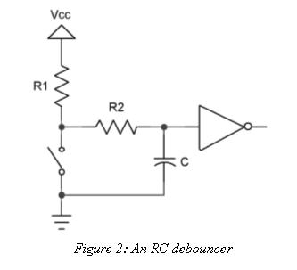
  • I'm a liar. dbgjtag works great! I had some denounce circuit (cap and resistor) on my reset switch. removing that made the unlock sequence work. The bricked boards are unbricked!
  • You are surely MORE than that - but does not "everyone - everywhere" employ such debounce circuit upon the MCU's reset line?

    Unless you had "non conforming value and/or performing" components - I cannot see such a requirement (remove all reset circuitry) as being necessary!    (or - if you had lowered the MCU's system clock SO FAR - it may be that the, "Recovery from reset was degraded...")

    I cannot determine if your boards are Eval or LPad - which should include "proper" value, MCU reset line components.     Faulty components and/or bad connections - to me - are the only "reasonable" explanation...

    Having been on this forum - and its predecessor - (forever) NEVER has such an "Escape from LOCKED" via "Removal of the Reset Line components" been noted!     Further - w/out the pull-up R - the treatment of the Reset line proves "uncertain" - I don't believe that it is able to properly recover when "released from your "Switch to Ground."     (i.e. something here is "rotten")

    [edit - add on]  thinking a bit more - if the Reset circuit pull-up R was too low in value (substantially low) then the board's 3V3 may have dropped "out of spec" but ONLY while the Reset Switch was HELD - which may explain why the earlier attempts to "Unlock" failed...     Allowing the MCU's Reset pin to float is NEVER best practice!    (as you seem to suggest)

  • cb1,

    I agree that a reset debounce circuit is unnecessary. I have 4 other switches that users press, and the user switches need to be debounced (so one press doesn't become four). I debounced ALL switches including reset. Reset was not specifically debounced; it just got included.

    This puts a small resistor between the micro pin and the switch. The debugger connects directly to the reset pin. My assumption is the debugger was able to un-assert the reset signal due to that tiny resistor between the pin and the closed switch. I believe this because the reset pin does work, but it does not complete the unlock procedure until the debounce is removed.

    SysCtlClockSet() was bricking my microcontroller because I have my 32KHz RTC and the 25MHz main osc swapped. After a little surgery, they are corrected, and Tivaware is working very well.

  • Thank you for such detail - appreciated. May I note that the "RC debouncer" presented is "classic" - our firm has used - and "never/ever" have we felt the need to "remove components" to achieve objectives. (although we use a highly proper JTAG Pod (J-Link - the industry leader.) One wonders if your, "newer, lesser, limited" JTAG Pod is cause and/or contributor to your issue?
  • Peter Borenstein said:

    I'd make sure that inverter was a Schmidt, however you might be better off choosing your supervisory circuit to be one with a switch input.

    Robert

  • Wait - just now noted the "inverter!"      Should not the MCU's reset be "pulled High" for normal operation?      As shown - when the switch is "normally open" the inverter will "drive the MCU's Reset to (near) ground!"

    That's just WRONG - there appears no such "inverter" upon the "4C123" LPad's Reset Line!       And now note poster's MCU is 4C129 - does it seek Reset @ Gnd - for normal operation?    Really?

    [edit]  Poster "seeks" and finds:   " 

    which clearly indicates that MCU's Reset line is "conventional" (i.e. logic high to operate, logic low to Reset - the inverter (w/its input pulled up) operates (in reverse) of that (long) standard!

    Is it not (now) proven that the WRONG Post was "Verified?"

  • I had assumed that it was an input into another circuit. After all feeding the reset line with a logic gate is a bad idea.

    Robert
  • The image is just one of the first google hits for "debounce circuit". Replace the gate with a micro pin.

    The reset switch was as secondary problem that prevented the first problem from resolution:

    Micro can't turn on crystal => unresponsive to debugger => Bobs suggest JTAG erase and Uniflash => JTAG erase didn't work => reset line fixed => JTAG erase works => crystal fixed
  • Peter Borenstein said:
    eplace the gate with a micro pin.

    That suggests you are connecting the reset pin directly to a switch. Probably a bad idea.

    Robert