Hi guys, I'm trying to build a program that controls the LED RGB intensity using PWM, but there's a catch, the value of the intensity MUST be entered using serial communication (UART) via Putty. In both cases, interruptions must be used.
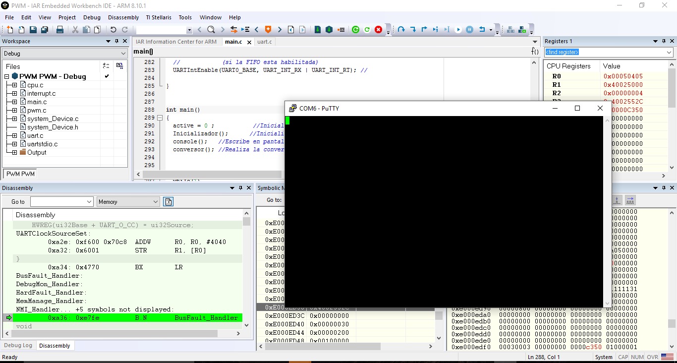
There are no compilation errors, put when the program runs on the launchpad, it doesn't show anything on putty (it's set correctly), and when the program is paused, it frezees on busfaulthandler or falut handler.
If you could give me a hand on what the problem is, i'd appreciate.
Thanks in advance. Mili
The program is the following:
#include <stdio.h>
#include <stdlib.h>
#include <stdint.h>
#include <stdbool.h>
#include <string.h>
#include "math.h"
#include "inc/hw_ints.h"
#include "inc/hw_timer.h"
#include "inc/hw_memmap.h"
#include "inc/hw_types.h"
#include "inc/hw_gpio.h"
#include "driverlib/interrupt.h"
#include "driverlib/gpio.c"
#include "driverlib/gpio.h"
#include "driverlib/pin_map.h"
#include "driverlib/pwm.h"
#include "driverlib/sysctl.c"
#include "driverlib/sysctl.h"
#include "driverlib/Timer.c"
#include "driverlib/Timer.h"
#include "driverlib/uart.h"
#include "utils/uartstdio.h"
#include "system_Device.h"
// Variables globales
volatile int brillo, counter=0;
char cadena[8];
int numero=0;
volatile int active = 0;
void console(void)
{
char c;
int counter=0;
numero=0;
// Funcion para imprimir en la pantalla PuTTy
while (counter == 0)
{
// Si se recive un caracter, este es leido y luego escrito en el transmisor.
// Es un "eco" de lo enviado.
if (UARTCharsAvail(UART0_BASE))
{
c= UARTCharGet(UART0_BASE); //Leo el caracter
cadena[numero]=c; //Lo guardo en la cadena
if ((c == '0')||(c == '1')||(c == '2')||(c == '3')||(c == '4')||(c == '5')||(c == '6')||(c == '7')||(c == '8')||(c == '9')||(c == '\r'))
{
if (c == '\r')
{
counter =1; //Finalizo la cadena
}
numero++;
UARTCharPut(UART0_BASE, c); // Lomismo que recibe lo transmite
}else
{
numero=0; //Si no es un número reinicio la cadena
UARTprintf("\nError - Brillo incorrecto\n");
UARTprintf("Ingrese el numero de brillo seguido de la tecla (enter)\n");
}
}
}
}
void conversor(void)
{
int f,i;
int p;
brillo=0;
// Realizo la conversión de caracteres a numeros reales.
f= numero-1;
for (i=0;i<f;i++)
{
if (i == 0)
p = 1;
else
p *= 10;
brillo = brillo + (((int)cadena[f-1-i]-48)*p); // conversión a entero
}
UARTprintf("\n\n");
UARTprintf("\nBrillo elegido: %i\n",brillo); // Imprimo el valor de brillo
}
// Rutina de servicio de interrupcion (ISR) de PWM
void PWM1IntHandler(void)
{
//
// Clear the PWM1 LOAD interrupt flag. This flag gets set when the PWM
// counter gets reloaded.
//
PWMGenIntClear(PWM1_BASE, PWM_GEN_2, PWM_INT_CNT_LOAD);
PWMGenIntClear(PWM1_BASE, PWM_GEN_3, PWM_INT_CNT_LOAD);
//
//Reset the duty cycle to 0.1% cycles. Note that 64 is
// 0.01% of the period (64000 cycles).
//
PWMPulseWidthSet(PWM1_BASE, PWM_OUT_2, 64);
PWMPulseWidthSet(PWM1_BASE, PWM_OUT_3, 64);
active =1;
}
// Rutina de servicio de interrupcion (ISR) de UART
void UARTIntHandler(void){
uint32_t ui32Status;
ui32Status = UARTIntStatus(UART0_BASE, true); // Se lee el estado de la interrupcion
// para saber cual fue el evento que
// genero la interrupcion.
UARTIntClear(UART0_BASE, ui32Status); // Se "limpian" o resetean los bits
// correspondientes a la interrupcion generada.
active=1; // Aviso que se activó UART
}
void Inicializador(void)
{
//********************************************************************
//***************************UART*************************************
//********************************************************************
// Habilitar GPIO puerto A que se utiliza para UART0.
SysCtlPeripheralEnable(SYSCTL_PERIPH_GPIOA);
// configurar los pines para muxing funciones UART0 en el puerto A0 y A1.
GPIOPinConfigure(GPIO_PA0_U0RX);
GPIOPinConfigure(GPIO_PA1_U0TX);
// Habilitar UART0 para que podamos configurar el reloj.
SysCtlPeripheralEnable(SYSCTL_PERIPH_UART0);
// Utilizar el oscilador de 16MHz interna como fuente de reloj UART.
UARTClockSourceSet(UART0_BASE, UART_CLOCK_PIOSC);
// Seleccionar la función alternativa (UART) para estos pasadores.
GPIOPinTypeUART(GPIO_PORTA_BASE, GPIO_PIN_0 | GPIO_PIN_1);
// Inicializar el UART para la consola de E / S.
UARTStdioConfig(0, 115200, 16000000);
//**************************************************************************
//*************************clock del sistema********************************
//**************************************************************************
// Seteo el clock
SysCtlClockSet(SYSCTL_SYSDIV_1|SYSCTL_USE_PLL|SYSCTL_OSC_MAIN|SYSCTL_XTAL_16MHZ);
//***************************************************************************
//*******************************PWM*****************************************
//***************************************************************************
unsigned long ulPeriod;
//
// Set the PWM clock to the system clock.
//
SysCtlPWMClockSet(SYSCTL_PWMDIV_1);
SysCtlPeripheralEnable(SYSCTL_PERIPH_PWM1); //The Tiva Launchpad has two modules (0 and 1). Module 1 covers the LED pins
ulPeriod = SysCtlClockGet() / 250; //PWM frequency 250HZ
//Configure PF1,PF2,PF3 Pins as PWM
GPIOPinConfigure(GPIO_PF1_M1PWM5);
GPIOPinConfigure(GPIO_PF2_M1PWM6);
GPIOPinConfigure(GPIO_PF3_M1PWM7);
GPIOPinTypePWM(GPIO_PORTF_BASE, GPIO_PIN_1 | GPIO_PIN_2 | GPIO_PIN_3);
//Configure PWM Options
//PWM_GEN_2 Covers M1PWM4 and M1PWM5
//PWM_GEN_3 Covers M1PWM6 and M1PWM7
//
// Configure the PWM1 to count down without synchronization.
//
PWMGenConfigure(PWM1_BASE, PWM_GEN_2, PWM_GEN_MODE_UP_DOWN | PWM_GEN_MODE_NO_SYNC);
PWMGenConfigure(PWM1_BASE, PWM_GEN_3, PWM_GEN_MODE_UP_DOWN | PWM_GEN_MODE_NO_SYNC);
//
// Set the PWM period to 250Hz. To calculate the appropriate parameter
// use the following equation: N = (1 / f) * SysClk. Where N is the
// function parameter, f is the desired frequency, and SysClk is the
// system clock frequency.
// In this case you get: (1 / 250Hz) * 16MHz = 64000 cycles. Note that
// the maximum period you can set is 2^16.
//
//Set the Period (expressed in clock ticks)
PWMGenPeriodSet(PWM1_BASE, PWM_GEN_2, ulPeriod);
PWMGenPeriodSet(PWM1_BASE, PWM_GEN_3, ulPeriod);
// Enable the PWM generator
PWMGenEnable(PWM1_BASE, PWM_GEN_2);
PWMGenEnable(PWM1_BASE, PWM_GEN_3);
// Turn on the Output pins
PWMOutputState(PWM1_BASE, PWM_OUT_5_BIT |PWM_OUT_6_BIT|PWM_OUT_7_BIT, true);
//************************************************************************
//****************************GPIOF***************************************
//************************************************************************
//
// Enable the GPIO port that is used for the on-board LED.
//
SysCtlPeripheralEnable(SYSCTL_PERIPH_GPIOF);
//
// Enable the GPIO pin for the LED (PF1). Set the direction as output, and
// enable the GPIO pin for digital function.
//
GPIOPinTypeGPIOOutput(GPIO_PORTF_BASE, GPIO_PIN_1);
//
// Enable the GPIO pin for the LED (PF2). Set the direction as output, and
// enable the GPIO pin for digital function.
//
GPIOPinTypeGPIOOutput(GPIO_PORTF_BASE, GPIO_PIN_2);
//
// Enable the GPIO pin for the LED (PF3). Set the direction as output, and
// enable the GPIO pin for digital function.
//
GPIOPinTypeGPIOOutput(GPIO_PORTF_BASE, GPIO_PIN_3);
//************************************************************************
//*************HABILITACION DE INTERRUPCIONES DE PWM**********************
//************************************************************************
//
// Enable processor interrupts.
//
IntMasterEnable();
//
// Allow PWM0 generated interrupts. This configuration is done to
// differentiate fault interrupts from other PWM1 related interrupts.
//
PWMIntEnable(PWM1_BASE, PWM_INT_GEN_2);
PWMIntEnable(PWM1_BASE, PWM_INT_GEN_3);
//
// Enable the PWM0 LOAD interrupt on PWM0.
//
PWMGenIntTrigEnable(PWM1_BASE, PWM_GEN_2, PWM_INT_CNT_LOAD);
PWMGenIntTrigEnable(PWM1_BASE, PWM_GEN_3, PWM_INT_CNT_LOAD);
//
// Enable the PWM0 interrupts on the processor (NVIC).
//
IntEnable(INT_PWM1_2);
IntEnable(INT_PWM1_3);
//
// Enable the PWM0 output signal (PD0).
//
PWMOutputState(PWM1_BASE, PWM_OUT_5_BIT, true);
PWMOutputState(PWM1_BASE, PWM_OUT_6_BIT, true);
PWMOutputState(PWM1_BASE, PWM_OUT_7_BIT, true);
//
// Enables the PWM generator block.
//
PWMGenEnable(PWM1_BASE, PWM_GEN_2);
PWMGenEnable(PWM1_BASE, PWM_GEN_3);
//**************************************************************************
//****************HABILITACION DE INTERRUPCIONES UART***********************
//**************************************************************************
IntMasterEnable(); // Habilitamos interrupciones de procesador
IntEnable(INT_UART0); // Habilitamos interrupciones provenientes de UART0
// Habilitamos generacion de interrupciones a la recepcion de un caracter (RX) o cuando se
// produce un timeout de recepcion (RT)
// La interrupcion a la recepcion (RX) se genera cuando:
// - se recibe un caracter (con FIFO desabilitada),
// - o cuando se alcanza o cuando se alcanza el nivel especificado en la FIFO
// (si la FIFO esta habilitada)
UARTIntEnable(UART0_BASE, UART_INT_RX | UART_INT_RT); //
}
int main()
{
active = 0 ; //Inicializo que el SW2 se encuentra apagado
Inicializador(); //Inicializo las variables, pueros, interrupciones y clock
console(); //Escribe en pantalla
conversor(); //Realiza la conversión de la cadena a enteros
// bucle infinito para ejecutar la interrupción
while(1)
{
if (active == 1)
{
active = 0;
int counter=0;
UARTprintf("Inicio de PWM \n");
// Encendemos LED verde con PWM
PWMPulseWidthSet(PWM1_BASE, PWM_OUT_7, brillo);
SysCtlDelay( (SysCtlClockGet()/(3*1000)) );
console();
conversor();
}
}
}