This thread has been locked.

If you have a related question, please click the "Ask a related question" button in the top right corner. The newly created question will be automatically linked to this question.

RTOS/TM4C129ENCPDT: SPI Port changes for CC3100 module communication not functional

Part Number: TM4C129ENCPDT
Other Parts Discussed in Thread: CC3100

Tool/software: TI-RTOS

Hi Everyone,

To give a brief info about what I'm trying to achieve 

I have TM4C129X development board and trying to integrate cc3100 wifi module with it. Im using simplelink libraries and successful in communicating with sample wifi example 

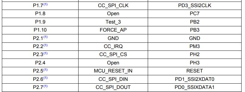
Now when it comes to modifying the SPI pins as per my proto board , Im facing issue where after successful "WiFi_open(Board_WIFI, Board_WIFI_SPI, NULL, &wifiParams);" function call , next when it calls "sl_Start" the system hangs and i cant debug further since "sl_Start" is a library, so im assuming there is some routine inside "sl_Start" which is waiting for some ACK from Wifi chip.

I also observed that if i change the IRQ pin from PORT M.3 to some other pin for example PORT P.0 (other pins left unchanged) the firmware again waits in infinite loop

Below is my initialization code

WiFiCC3100_Object wiFiCC3100Objects[EK_TM4C129EXL_WIFICOUNT];

const WiFiCC3100_HWAttrs wiFiCC3100HWAttrs[EK_TM4C129EXL_WIFICOUNT] = {
{
.irqPort = GPIO_PORTM_BASE,
.irqPin = GPIO_PIN_3,
.irqIntNum = INT_GPIOM,

.csPort = GPIO_PORTB_BASE,
.csPin = GPIO_PIN_4,

.enPort = GPIO_PORTP_BASE,
.enPin = GPIO_PIN_1
}
};

const WiFi_Config WiFi_config[] = {
{
.fxnTablePtr = &WiFiCC3100_fxnTable,
.object = &wiFiCC3100Objects[0],
.hwAttrs = &wiFiCC3100HWAttrs[0]
},
{NULL,NULL, NULL},
};

/*
* ======== EK_TM4C129EXL_initWiFi ========
*/
void EK_TM4C129EXL_initWiFi(void)
{
/* Configure EN & CS pins to disable CC3100 */
GPIOPinTypeGPIOOutput(GPIO_PORTB_BASE, GPIO_PIN_4);
GPIOPinTypeGPIOOutput(GPIO_PORTP_BASE, GPIO_PIN_1);
GPIOPinWrite(GPIO_PORTB_BASE, GPIO_PIN_4, GPIO_PIN_4);
GPIOPinWrite(GPIO_PORTP_BASE, GPIO_PIN_1, 0);

/* Configure SSI2 for CC3100 */
SysCtlPeripheralEnable(SYSCTL_PERIPH_SSI1);
GPIOPinConfigure(GPIO_PB5_SSI1CLK);
GPIOPinConfigure(GPIO_PE4_SSI1XDAT0);
GPIOPinConfigure(GPIO_PE5_SSI1XDAT1);
GPIOPinTypeSSI(GPIO_PORTE_BASE, GPIO_PIN_4 | GPIO_PIN_5 );
GPIOPinTypeSSI(GPIO_PORTB_BASE, GPIO_PIN_5);

/* Configure IRQ pin */
GPIOPinTypeGPIOInput(GPIO_PORTM_BASE, GPIO_PIN_3);
GPIOPadConfigSet(GPIO_PORTM_BASE, GPIO_PIN_3, GPIO_STRENGTH_2MA,
GPIO_PIN_TYPE_STD_WPD);
GPIOIntTypeSet(GPIO_PORTM_BASE, GPIO_PIN_3, GPIO_RISING_EDGE);

SPI_init();
EK_TM4C129EXL_initDMA();

WiFi_init();
}

Thanks in Advance

-Prajnith

  • Hi Prajnith,
    Have you had a chance to reference the TI design using TM4C129 with CC3100? In section 3 of the userguide there is signal mapping between the two processors over the SPI communication.

    www.ti.com/.../tidu992.pdf
    www.ti.com/.../TIDM-TM4C129XWIFI
  • Hi Charles,

    Thanks for quick reply, Just to clarify I'm able to connect to cc3100 using sample example but i face issue when i change the default ports/pin to pins specific to my requirement, especially SPI and IRQ pins. I need some help if the code i pasted earlier is valid or not. I see that we are enabling interrupt for IRQ pin, so do we need to specify interrupt handler explicitly or will the simple link library handle it? Similarly is there any limitation on using SPI ports other than the default SPI port mentioned in the sample example?

    Thanks,

    -Prajnith

  • Just to add to above comment, if i change the IRQ port M pins , example from M.3 to M.6 it still works but the moment i change the port itself IRQ stops working.
  • Hi Prajnith,

     I don't see problem with the code you pasted in a standing-alone context. The question to ask is if you are using the booster pack on top of the launchpad? When you change the SPI pins on the MCU side from SSI2 (as in the example) to SSI1 then the SPI interface no longer connect with the CC3100 via the bootster connectors. 

      As far as the IRQ goes, you change from the PM3 to a different port, i.e. PORTA, then you will need update the interrupt handler as well. PORTM is mapped to vector 88 in the NVIC. Say you want to map the IRQ to PORTA, then you will need to add an handler for PORTA which is mapped to vector 16. 

  • Hi Charles,

    Thanks for through explanation.

    Actually I was able to fix the IRQ issue but not sure how  exactly it got fixed. Well what I did was, I copied all the  WiFi and simplelink code which was referenced from TI  Tiva folder to my main project so that I could debug the WiFi api's but by copying  the WiFi library files to my main project same how fixed the issue. I'm not sure what was going wrong earlier when I was refencing the WiFi libraries from TI install folder.

    Coming to SPI, yes I'm using wifi Booster pack but I didn't mount it on TIVA board but have interfaced it via breakout wires. So that I can connect to respective ports.

    Since I was unable to get CC3100 working with SPI 1 port, I gave SPI 3 port a try and it worked.

    The only major difference I'm seeing between SPI1 port and SPI2, 3 port is that, in SPI1 the MISO and MOSI are on PORT E and CLK is on PORTB but in SPI2, 3 the MISO, MOSI and CLK are placed on same ports. I know this should not be any issue since it's internally muxed to Spi Pheripheral, but just an observation.

    Also I forgot to mention earlier, in the CC3100 example the SPI PORTS are mapped with dma.

    It would be really helpful if you could confirm if there is any restrictions on using SPI 1 PORT along with DMA

    Thanks

    -Prajnith

  • Hi Prajnith,
    I assume you are talking about the uDMA, correct? Since you asked about SPI 1 PORT along with DMA, that brings up a good point to check. If the uDMA is utilized in the example for SSI1 then you will need to modify the uDMA control structure if you were to use a different SSI.
  • I modified the DMA channel selection accordingly for SPI 3 but when I modified for SPI 1, it didn't work. I will share rest of the code once I get back to my pc.

    Thanks
    -Prajnith
  • Prajnith,
    Please also use the scope to observe the SPI1. The MCU should be the master so it should generate the SPICLK. Do you see the SPICLK and SIMO activities?
  • Hi Charles,

    After going through Reference manual i changed the uDMA from Secondary to Primary and channel from 10,11 to 24,25 and then it worked.

    -Prajnith
  • Glad your problem is solved.