This thread has been locked.

If you have a related question, please click the "Ask a related question" button in the top right corner. The newly created question will be automatically linked to this question.

EK-TM4C123GXL: Porting Clock Functionality from MSP430F5529

Part Number: EK-TM4C123GXL
Other Parts Discussed in Thread: MSP430F5529, SW-TM4C, TM4C123GH6PM, , TIDM-VOICEBANDAUDIO

Hi,

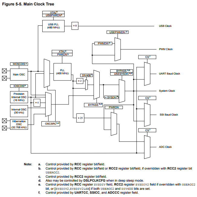
I am currently working on a potential audio solution for a customer using an MSP430F5529 Launchpad and voice band audio booster pack. The booster pack generates sound via .wav files stored in spi flash. The PWM signal is sent through a low pass filter and audio amplifier before playback by the speaker. I have attached the reference design .pdf for your reference.

The current design supports playback at 8, 16, 22, and 44kHz. The customer is very interested in this functionality, however they are interested in the tm4c123 chip as the processor for their design. Therefore, I am now working the get the same functionality out of the tiva device.

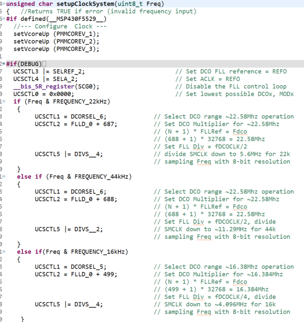
The first task is initializing the tiva's clock in the same way the msp430 was done:

I was wondering if there was any collateral or support on how to port this over for the tiva device.

Thanks,

Garrett

PWM_DAC_Design.pdf

  • Hello Garrett,

    The first thing I would do is investigate the software used by the MSP430 example and ascertain if they used the MSP430 DriverLib for it.

    If so, then you should be able to find matching API's for a number of functions within the TivaWare DriverLib which would simplify the porting process in that you'd just need to determine which variables to pass in at that point.

    In any event, you will want to familiarize yourself with TivaWare to handle this: www.ti.com/tool/sw-tm4c
  • Hi Garrett,

    Looks like you added an image since I first looked at the post.

    For clock initialization, you won't want to use register level commands but rather a TivaWare API. Specifically, SysCtlClockFreqSet which is documented in this document in Section 26.2.2.2: www.ti.com/.../spmu298d.pdf

  • Hi Ralph,

    I have shaped a timer example from TIVAware into a working prototype. I am currently using an 80MHz system clock and Timer 3 in PWM mode to output a signal to pin PB2 at 16kHz.

    However, moving forward I would like to have Timer 3 operating at 4.096MHz, while the system clock remains at 80MHz, to produce a 16kHz PWM signal. I can't seem to find an API in driverlib that supports this division from the system clock. I have attached a snippet of my code for your reference.

    Thanks,

    Garrett 

  • Garrett Mize said:
    However, moving forward I would like to have Timer 3 operating at 4.096MHz, while the system clock remains at 80MHz, to produce a 16kHz PWM signal. I can't seem to find an API in driverlib that supports this division from the system clock.

    The Main Clock Tree from the TM4C123GH6PM datasheet shows that the PWM Clock can only be a divided down version of the System Clock:

    Where the PWM clock can be the System Clock divided by 1, 2, 4, 8, 16, 32 or 64 (PWM_SYSCLK_DIV_1,PWM_SYSCLK_DIV_2, PWM_SYSCLK_DIV_4, PWM_SYSCLK_DIV_8,PWM_SYSCLK_DIV_16, PWM_SYSCLK_DIV_32, or PWM_SYSCLK_DIV_64).

    Given the clock tree restrictions, I think the closest you can get to the required clock configuration is:

        /* Set the system clock to run at 66.67 MHz off the PLL with external crystal as reference. */
        SysCtlClockSet (SYSCTL_SYSDIV_3 | SYSCTL_USE_PLL | SYSCTL_XTAL_16MHZ | SYSCTL_OSC_MAIN);
    
        /* Set the PWM clock to 4.17 MHz */
        SysCtlPeripheralEnable (SYSCTL_PERIPH_TIMER3);
        PWMClockSet (TIMER3_BASE, PWM_SYSCLK_DIV_16);

    The PWM clock will be 4.17 MHz which is +1.7% higher than the ideal frequency of 4.096 MHz. Not sure if that frequency error will cause a problem for an audio application.

    [I haven't tested the suggested clock configuration]

  • Garrett,
    The closest to 4.096MHz you can obtain on a TM4C123 is either 4.167MHz (with the main clock @66.67MHz or 50MHz) or 4.21MHz (with the main clock @80MHz).
    No need to use the PWM peripheral for that (or pre-dividers, which GPTM's don't have in Tivas), just use GP Timer on with the proper load set.
    Any of these main clocks will allow also divisions that get very close to 8K, 16K, 22K and 44KHz.
    As for the main clock, I understand that the fastest your main clock, the more you will have"sound resolution" available - not sure if that will influence on the applications desired sound quality, but it might be good to run the chip as fast as possible.
    Bruno
  • Ralph Jacobi said:
    ...TivaWare API. Specifically, SysCtlClockFreqSet

    While not overwhelmingly clear - vendor poster is using "4C123" thus the "SysCtlClock" function must be chosen to support it - not the 4C129.

    No mention is made of the required frequency accuracy - w/out that (key) guidance I offer the following"

    • there are (now) "tunable oscillators" - which may be able to "dial in" to the chosen frequency  (likely add size and cost)
    • firm/I have - on several occasions - "tested & binned" various xtals & xtal osc - which allowed a "better match" to the desired frequency.    (some consultation w/xtal vendor proves useful)   

    What is the role of "4.096MHz" - such was unstated or my (multiple) reads "missed?"

    As always - "abbreviated" details - delay & impede guidance... 

  • cb1_mobile said:
      Further - what is the role of "4.096MHz" - such was unstated or my (multiple) reads "missed?"

    The application is playing back 8-bit audio sampled at 16 KHz.

    The PWM output is passed through a low-pass filter to build a DAC.

    The rationale behind the 4.096 MHz PWM clock is that is 256 times the audio sampling rate of 16 KHz, such that with the PWM GPTMTnILR load value set to 256 the 8-bit audio sample value can be written to the PWM GPTMTnMATCHR match value.

  • Chester,

    Thank you (rapid-fire & precise) becoming more & more your "trademark!"

    While firm/I have "general awareness" of audio sampling rates - others may be chosen - IIRC even higher rates have taken hold @ "industry leaders."

    The post provides NO target for accuracy, speed of response etc. - thus raises (many) questions...     (the use of the "tunable oscillator" requires (some) indication of  frequency accuracy demanded - and NONE was provided!)

  • In that case, would the application also need a 256 * 44KHz when playing at that higher resolution?
    It is getting harder to generate a PRECISE 11.264MHz signal on a TM4C123...
    It's been ages since I played with MSP430's, but can they do such magic? Their master clocks are 16MHz and 20MHz if I'm not mistaken...
  • Bruno Saraiva said:
    In that case, would the application also need a 256 * 44KHz when playing at that higher resolution?

    Yes

    Bruno Saraiva said:
    It's been ages since I played with MSP430's, but can they do such magic? Their master clocks are 16MHz and 20MHz if I'm not mistaken...

    The MSP430 Frequency Locked Loop (FLL) allows the system clock frequency to be set to an integer multiple of a 32768 Hz crystal, which allows a finer selection of clock frequencies than the TM4C123 approach of  division down from the internal PLL frequency of 400 MHz.

    Bruno Saraiva said:
    It is getting harder to generate a PRECISE 11.264MHz signal on a TM4C123...

    A different approach would be to set the TM4C123 system clock and PWM clock frequency to 80MHz, but to re-scale the 8-bit audio samples to a different PWM GPTM Timer n Interval Load than 256. E.g.

    1) For 8 bit audio at 16 KHz:

    a) Set the TM4C123 system clock and PWM clock frequency to 80 MHz.

    b) Set the PWM GPTM Timer n Interval Load to 5000 = 80 MHz / 16 KHz. This is an exact integer division.

    c) Set the PWM GPTM Timer n Match to ((8-bit audio value) * 5000) / 256.

    2) For 8 bit audio at 44100 Hz:

    a) Set the TM4C123 system clock and PWM clock frequency to 80 MHz.

    b) Set the PWM GPTM Timer n Interval Load to 1814 = integer value of (80 MHz / 44100 Hz). This generates a payback frequency of 44101.43 Hz or an error of +0.003%

    c) Set the PWM GPTM Timer n Match to ((8-bit audio value) * 1814) / 256.

    For 2c) and 2c) a 256-entry loop-up table could be created to give the translation from the 8-bit audio sample from the file into the value to write into the PWM GPTM Timer n Match register, to avoid the need to perform the re-scaling calculation on the fly.

  • All good & further information - time/effort/thought of "helpers" appears to have exceeded that of the originator.

    Chester Gillon said:
    MSP430 Frequency Locked Loop (FLL) allows the system clock frequency to be set to an integer multiple of a 32768 Hz crystal

    Indeed this "Up-Scaling" of so low a frequency does provide a, "more granular end frequency."      But - that's not without trade-offs (perhaps warrants mention) - the most notable being any "change/shift" in xtal frequency - undergoes that (same) Up-Scale "Multiplication Factor" - creating the potential for "large" errors in frequency!    It too should be noted that any change in temperature, voltage, xtal aging - also will impact frequency accuracy and stability - again "magnified" due to that multiplication.  

    "Real" frequency "standards" (i.e. precision oscillators - even those w/ "ovens") are thus far more likely to "Scale-Down" from a higher frequency - as the "Frequency Division" has the effect of "reducing" frequency error and/or drift - not "compounding" the error - as achieved via "multiplication."

    Long ago (hopefully not continued today) top cabin Ham Receivers included a 100KHz (tweakable) oscillator - so that (some) secondary measure of frequency could be provided.     in the case of the 20 Meter Ham Band - that xtal freq. was multiplied by 140 (along w/any error/drift/other etc.) - which degraded frequency (accuracy & stability) by the extent of the multiplication...

  • cb1_mobile said:
    Indeed this "Up-Scaling" of so low a frequency does provide a, "more granular end frequency."      But - that's not without trade-offs (perhaps warrants mention) - the most notable being any "change/shift" in xtal frequency - undergoes that (same) Up-Scale "Multiplication Factor" - creating the potential for "large" errors in frequency!  

    As well as the mean frequency error, the MSP430 FLL introduces short-term jitter on the clock. That is because the FLL of the MSP430 UCS module stabilizes the DCO output by switching between two frequencies: fDCO and fDCO+1 (the FLL modulator mixes two frequencies to produce the DCO clock).

    cb1_mobile said:
    It too should be noted that any change in temperature, voltage, xtal aging - also will impact frequency accuracy and stability - again "magnified" due to that multiplication.  

    Agreed. However, not all applications require the same frequency accuracy. In this case of the application in this thread of replaying sampled audio, say a recording of speech, how much of a frequency error before the audio is no longer recognisable to a human listener?

  • Chester Gillon said:
    not all applications require the same frequency accuracy ... i.e.  replaying sampled audio, say a recording of speech, how much of a frequency error before the audio is no longer recognizable to a human listener?

    Exactly!    And such was my (earlier) point re: "absence of the (needed) key specifications" - which (somehow) did not make it into originator's postings...   Note that (vendor) poster did provide certain "detail" but the bulk was outside the description of his central inquiring thrust.     (i.e. generating a frequency of adequate accuracy & stability - to yield "satisfactory" results.    (with "satisfactory" strangely undefined!)

  • Chester Gillon said:

    1) For 8 bit audio at 16 KHz:

    a) Set the TM4C123 system clock and PWM clock frequency to 80 MHz.

    b) Set the PWM GPTM Timer n Interval Load to 5000 = 80 MHz / 16 KHz. This is an exact integer division.

    Or set it to 255. That makes filtering the result a lot easier and preserves your 8 bit load. Then just reload at 16kHz. You do get a non integer number of PWM cycles per sample but the filtering may well mask that even though it's less than you would need for a 16kHz PWM. With the reduced filtering I would expect you might actually have improved fidelity.

    Even so a 16kHz lookup wouldn't be especially difficult. For that matter a calculation to rescale the sample wouldn't impose much overhead.

    Robert

  • Hi Chester,

    Your response has provided me with some valuable insight. However, I have a few questions. The goal of this exercise was to demo audio playback to the customer at 16kHz. The method implemented on the MSP430 uses a 4.096MHz clock to produce 8 bit, 16kHz audio playback. I am simply wanting to replicate this as closely as possible. No strict error specifications are in place at the moment.

    1. Is this method using the TM4C123G's PWM timer mode or the PWM module?

    2. Would these two lines for the PWM clock be added in addition to my existing code or replace it? I believed I had already enabled Timer 3 and still would like for it to output on pin PB2.

    The goal of this exercise was to demo audio playback to the customer at 16kHz. The method implemented on the MSP430 uses a 4.096MHz clock to produce 8 bit, 16kHz audio playback. I am simply wanting to replicate this as closely as possible. No strict error specifications are in place at the moment.

    Thanks,
    Garrett
  • Bruno,

    I am curious as to how you arrived at 4.21MHz? I believe the end customer will want to run the chip as fast as possible (80MHz) so this would be the ideal configuration to demo for them. However, I am having slight trouble understanding where the 4.21MHz comes from. I am currently running on an 80MHz clock and setting the load to 5000 which gives me a playback of 16kHz.

    Thanks,
    Garrett
  • Garrett,
    That's the result of a division using the most adequate integer load on a Timer.
    80000000 / 19 = 4210526
  • Hi,

    Apologies for my inactivity after posting Friday afternoon. I was out of town enjoying time with my family for the weekend.

    As for your questions of specifications the goal of this exercise was to demo audio playback to the customer at 16kHz. They would like the lowest playback frequency possible, for maximum spi flash space, and for the chip to operate as fast ass possible (80MHz). After implementing the demo code provided on the MSP430, 16kHz was deemed to be the lowest playback acceptable for sound quality

    The method implemented on the MSP430 uses a 4.096MHz clock to produce 8 bit, 16kHz audio playback. The PCM wave is compared to an up counter with a load of 0xFF (255). Once the match value is hit, the output PWM is driven low until the beginning of the next clock cycle. I am simply wanting to replicate this as closely as possible.

    For "satisfactory" results I would like to playback a .wav file at 16kHz with the system clock running as closely to 80MHz as possible. No strict error specifications are in place at the moment as I am trying to establish a working demo to build on.
  • Bruno,

    I see. I guess a better question would be what driverlib API is used to divide down Timer 3 from the system clock to then assign a load and match too? I was a little confused when you said to just use the right load value to divide down.

    //80MHz system clock
    ROM_SysCtlClockSet(SYSCTL_SYSDIV_2_5 | SYSCTL_USE_PLL | SYSCTL_OSC_MAIN | SYSCTL_XTAL_16MHZ);

    ///////////////////
    Timer 3 = 80MHz / 19
    //////////////////

    ulPeriod = 255;
    ROM_TimerLoadSet(TIMER3_BASE, TIMER_A, ulPeriod); // 4.21MHz / 255 = 16.5kHz playback

    Ultimately I would like my load value for the down counter to be 0xFF (255) for the match value to be compared to. I greatly appreciate your time and help.

    Thanks,
    Garrett
  • Garrett,

    I'll be surely willing to help further! However, I first need to state that my experience with audio is restricted to listening to Progressive Rock as much as possible, and to eventually hit some drums... Neither help at all converting wav files to audible air waves...

    Given I understand a bit of the analog audio concepts but the pwm use is just "something I know to be of existence", maybe the questions here will be naive... Let's do it anyway:

    - What does a WAV file contain? A somewhat binary representation of sequences of frequencies/intensities? (Maybe this would be too much to be explained here and a google search probably be a better source - feel free to skip this if that's the case).

    - I'm assuming your output is a PWM signal, correct? Is the period fixed, varying only duty? Or are both variable? How frequent is the signal configuration changed (16000 times per second, or 16000 x 256 times per second?) Maybe you can sketch the output here? I'm sure these are obvious and basic information for you, and while several posters here have excellent knowledge about pushing TM4C timers to the limit, not many seem to meander onto sound domains...

    Less relevant, but how are you obtaining the "wav audio bytes"? Do you have them in a RAM buffer? Did you manage the transfer from whatever external storage into the MCU's RAM (or maybe is it actually in the MCU?).

    Regards

    Bruno
  • Bruno,

    I appreciate your honesty, this is also a new challenge for me and would not mind figuring it out with you. Audio playback is certainly the end goal. However, I am first striving to understand how to set up the clocks in a similar manner on Tiva to produce a simple PWM output. I am just having trouble understanding how to get Timer 3 to run at around 4.096MHz while utilizing a load value of 255 to get a 16kHz playback.

    -WAV files are typically uncompressed audio files that have stored audio bit streams in PCM format (0's and 1's). The current MSP430 solution takes in an 8 bit segment of the .WAV at a time as a number and compares this "match value" to the "load" value. When match is hit, the output PWM signal is driven low until the next clock cycle/8 bits are loaded. A quick online search can provide in depth info if this is not sufficient.

    -You are correct, PWM is the output which is passed into a low pass filter to produce sine wave audio. Yes the period would remain fixed, I am only interested in altering the duty cycle to change pitch, sound, etc. One 8 bit sample is taken over a full "load" count/period. This is the out put of the current code I provided.

    -The MSP430 spi flash is loaded with sound files. The cpu then reads from the spiflash to provide samples to the CCR in the timer to produce a PWM output. I have not made it this far with the TIVA yet. I have been able to produce a 16kHz PWM output and vary the duty cycle manually, however this is with timer 3 running off the system clock (80MHz). I am trying to figure out how to configure timer 3 to 4.096MHz so that I may use a load value of 255 before I move forward with anything else.

    Thanks,

    Garrett

  • Bruno Saraiva said:
    - What does a WAV file contain?

    A wav file is just intensity vs time. If you displayed a microphone output on a 'scope, that's what the values in a wav file would look like.

    Bruno Saraiva said:
    - I'm assuming your output is a PWM signal, correct? Is the period fixed, varying only duty? Or are both variable? How frequent is the signal configuration changed (16000 times per second, or 16000 x 256 times per second?) Maybe you can sketch the output here? I'm sure these are obvious and basic information for you, and while several posters here have excellent knowledge about pushing TM4C timers to the limit, not many seem to meander onto sound domains...

    Also what are you doing with the PWM? Are you filtering it and passing the filtered signal to an audio amp circuit or are you running a class D amp directly? Both would probably benefit from higher PWM frequencies but the details would matter.

    Robert

  • Garrett Mize said:
    -You are correct, PWM is the output which is passed into a low pass filter to produce sine wave audio.

    What's your filter's frequency cutoff? (Given a 16kHz PWM, I'd hazard around 2kHz)

    Robert

  • 2703.PWM_DAC_Design.pdfHi Robert,

    The output PWM is being pushed through a low pass filter and audio amplifier before output on the speaker. I have attached the reference design documentation which contains the parts used on the audio booster pack.

    As I told Bruno I am simply using a logic analyzer at the moment on pin PB2 to look at the PWMs created on tiva. This is the pin that will eventually be used to output the signal to the booster back once the clocks are configured correctly.

    Thanks,

    Garrett

  • Garrett Mize said:
    The output PWM is being pushed through a low pass filter and audio amplifier before output on the speaker. I have attached the reference design documentation which contains the parts used on the audio booster pack.

    OK, an simple single pole RC low pass filter at ~3.7kHz (they're relying on the second stage to further filter).

    I would ditch the 16kHz requirement. You will get less transmitted noise with higher PWM frequencies (the filter will be more effective). There's a small chance there could be some pickup but it's less than the chance that matching 16kHz will give problems and about the same that the micro's clock will cause pickup issues.

    Overall, I can see no reason to keep 16kHz.

    Robert

  • Interesting to know about "what is the wav file"... I then tend to agree that 16kHz ain't the choice for TM4C's...
    Does a wave file have some sort of standard header which tells what frequency it's been recorded at?
    Given that the TM4C123 can quite easily change PWM duty loads much faster than 16000 times a second, I assume it would be "simple math" to employ a much finer resolution on the PWM output, while still changing "to the next intensity level" when the right time comes - does this make sense? Certainly much better for an analog filter!
    I believe that the optimum output frequency would be a influenced by:
    - the filter characteristics and
    - by what is a "reasonable" pwm setting with 256 evenly spaced levels to be managed by a 80MHz clock...
    Bruno
  • I see your point. The 16kHz requirement stemmed from the customers desire to maximize memory space by having the smallest files possible. Hence, 16kHz was the lowest frequency that sounded acceptable.

    Do you think something like 22kHz would be better? They are not interested in CD quality playback, only simple voice playback.

    -Garrett
  • Bruno Saraiva said:
    Does a wave file have some sort of standard header which tells what frequency it's been recorded at?

    I believe so, I don't know a lot about the details but the format is documented somewhere on line I'm sure.

    Bruno Saraiva said:
    I believe that the optimum output frequency would be a influenced by:
    - the filter characteristics and
    - by what is a "reasonable" pwm setting with 256 evenly spaced levels to be managed by a 80MHz clock...

    Pretty much. A simple RC filter such is on the board the OP is suing will be better at higher frequencies so from that perspective, the higher the better.

    A PWM should reload automatically so no overhead there.

    So first pass I'd set the PWM for an 8 bit duty cycle and just change the reload value at the sample rate. You could measure the distortion on a 'scope. I rather suspect the distortion introduced by the phase jitter in the output would be less than that introduced by using a 16kHz PWM.

    We're only talking telephone line voice quality so the requirements aren't getting into audiophool territory.

    Robert

  • Garrett Mize said:
    I see your point. The 16kHz requirement stemmed from the customers desire to maximize memory space by having the smallest files possible. Hence, 16kHz was the lowest frequency that sounded acceptable.

    A reasonable choice. Particularly if it's a noisy environment.

    Garrett Mize said:
    Do you think something like 22kHz would be better? They are not interested in CD quality playback, only simple voice playback.

    Keep the sample rate the same. Just change the PWM frequency. That 3.7kHz filter limits your sound quality to voice in any case (and your board docs mention that).

    The PWM frequency can rise to a few hundred kHz. I'd check that it can actually drive the filter to full range but I'd start with just a simple 8 bit duty cycle range and just let the frequency be whatever resulted.

    Robert

    80,000,000/256 ~= 312kHz

  • Garrett Mize said:
    1. Is this method using the TM4C123G's PWM timer mode or the PWM module?

    2. Would these two lines for the PWM clock be added in addition to my existing code or replace it? I believed I had already enabled Timer 3 and still would like for it to output on pin PB2.

    I was just making some initial suggestions on how to get the PWM clock frequency close to what the original MSP430 design used, without complete consideration of how to place the clock configuration in the code.

    As for use of the PWM timer mode .vs. the PWM module given that the design just requires single PWM output the PWM timer mode should be sufficient. The PWM timer mode can output on pin PB2 which on the EK-TM4C123GXL matches the PWM input expected by the TIDM-VOICEBANDAUDIO.

    Based upon Robert's suggestions don't see the need for the PWM period to be 16 KHz  (the audio sample frequency). Instead:

    1) Set the CPU clock frequency and timer module to the maximum of 80 MHz.

    2) Use timer 3 with a PWM period set to 256 clocks.

    3) At 16 KHz (the audio sample frequency) update the timer 3 PWM duty cycle using the next 8-bit audio sample value. The updates to the PWM duty cycle will be at approx 19.53 times the sampled audio rate which should help the RC filter on the board to remove the PWM harmonics.

    By starting with a sampled 1KHz sine-wave you could compare the output against Figure 21. 1-kHz Sine Wave at 16-kHz Playback Frequency in the MSP430 based design.

    When setting the PWM duty cycle you may need to offset the match value set to allow for either continuously low or continuously high outputs; see Figure 11-6. CCP Output, GPTMTnMATCHR > GPTMTnILR, Figure 11-7. CCP Output, GPTMTnMATCHR = GPTMTnILR and Figure 11-8. CCP Output, GPTMTnILR > GPTMTnMATCHR in the TM4C123GH6PM datasheet.

  • Garrett Mize said:
    Do you think something like 22kHz would be better? They are not interested in CD quality playback, only simple voice playback.

    If the audio files have already been recorded at 16KHz, I'd try and go to multiples of that. You'd simply be repeating the same PWM n times, with the benefit of less noise in the filter, but not increasing memory space... Maybe 64kHz?

    If the audio files are to be recorded, then a more serious analysis would be needed: what is really an optimum analog value, versus the MCU capacity... But in this case, memory would grow accordingly.

  • *Like*

    Chester Gillon said:
    When setting the PWM duty cycle you may need to offset the match value set to allow for either continuously low or continuously high outputs;

    Maybe not, it's audio, so no DC component. Clipping to remove the full on and full off values would likely not be noticeable.

    Quite right that you'd need it for a 'full' solution but it may not matter.

    Robert

  • Bruno Saraiva said:
    If the audio files have already been recorded at 16KHz, I'd try and go to multiples of that.

    I'd just go with the 8 bit sample size (or powers of two of it). Not much advantage to matching the PWM to the sample rate I think (remember there's a big low pass filter).

    Bruno Saraiva said:
    Maybe 64kHz?

    I'm thinking 312.5kHz

    Robert

  • Oh, makes perfect sense!!!
    Just go with the fastest PWM that allows for a 8-bit resolution. 80000000/256 = 312500.
    Then use a second timer running at the frequency of the recorded file. This second timer is responsible for changing the PWM match value to the new audio level.
  • Bingo. You'd want to verify the performance but it's fast and simple with little overhead.

    Robert
  • In case it helps, I have just noticed that  TivaWare_C_Series-2.1.4.178 contains a driver in examples\boards\dk-tm4c129x\drivers\sound.c for generating sound on a DK-TM4C129X by using the PWM timer mode.

    It may provide a suitable starting point for a driver on a EK-TM4C123GXL (I haven't checked sound.c for any TM4C129 specific TivaWare calls).