This thread has been locked.

If you have a related question, please click the "Ask a related question" button in the top right corner. The newly created question will be automatically linked to this question.

CCS/tm4c123gh6pm: No interrupts fire when using Segger J-Link

Part Number: TM4C123GH6PM
Other Parts Discussed in Thread: EK-LM3S811, LM3S811

Tool/software: Code Composer Studio

What needs to be done to enable interrupts when debugging a TM4C via Segger's J-Link?

My project uses the Timer0 interrupt. If I debug (from CCSv7.2) using the Stellaris (on-board) debugger, everything runs fine and interrupts fire. However, with the J-Link Segger Emulator, no interrupt occurs.

Note that I have double-checked that “Disable Interrupts” is unchecked “When running” (see image below).

Thanks for your help!

  • Beat Arnet said:
    However, with the J-Link Segger Emulator, no interrupt occurs.

    Our firm employs multiple such "J-Links" - never have we noted, "unwanted disabling of interrupts!"      And - you may note - J-Link & similar are NOT "Emulators" - they produce & process "Real JTAG protocol."

    To gain the optimal performance from such an effective JTAG "Probe" - many employ a "Pro IDE" (such as Keil or IAR).     It is suspected that (something) w/in your "CCS" set-up is impacting operation.   Again - never have firm - nor our multiple clients - encountered such a, "Loss of interrupts."

    How certain are you that the J-Link is "truly" attaching to your board and that "code updates" are (really) occurring?      (suggest that you make a very (slight) code change - download then to your board - and monitor to see if the "change" was detected...      It seems "outside" of the JTAG Probe's "charter" to impact the arrival of interrupts.

    Another suggestion would be to replace your existing (interrupt rejecting) code - and employ a "known good" vendor example project - making NO/ZERO changes.    A tall stack of "chips" are placed upon the "return" of interrupts - should you follow that direction...

  • I can confirm that the code is updated if I make changes, recompile, and flash.

    If I set breakpoints in the main loop (BKPT #0x00), the debugger will stop at those locations.

    If I set breakpoints in the interrupt routine (again, with BKPT #0x00), those are never hit.

    The same code debugged with the Stellaris Debug Probe fires interrupts correctly and will hit all breakpoints.

    The same code running freely without debugger connected fires interrupts correctly.

  • That's all good info - thank you. It is assumed (via MCU part no.) that yours is an "LPad" - not a custom board - please confirm.

    If indeed yours is an LPad - you must make a strategic implementation to "defeat" the "On board ICDI" - thus properly enabling your external JTAG Probe.      Such info has not been supplied - kindly detail.    (a schematic revealing any/all connections between the J-Link and your board.)     Again - if an "LPad" - it proves vital that you "hold the ICDI MCU in Reset" so that the ICDI does not "intrude signals" into the "external JTAG Probe's connections."     Thinking further - if all that you note is correct - such may point to a mishandling of MCU's Reset - by your "attachment" of the external JTAG Probe.   (schematic resolves!)

    Further - the use of "BKPT #0x00" is outside of my (ready) recognition.     It is known that 'too many" breakpoints will prevent the addition of new ones - might (that) be your issue?     (and kindly detail - or link - the "BKPT #0x00" official description for me - thank you.)

    Also - one wonders if your interrupts ARE being entered - yet your "use of breakpoints" (somehow) impedes.     Might you, "Toggle an Led w/in one of the interrupts" so that with the program RUNNING - any entry to the interrupt may be (in that manner) confirmed?

  • Yes, it is a Launchpad. I followed these instructions to make the connections:

    wiki.segger.com/TM4C123G_LaunchPad

    Since I can load, run and debug (other than interrupts), I would assume that my hookup is correct.

    But your comment regarding "hold the ICDI MCU in Reset" is intriguing. There is no reference to this on Segger's Wiki. But I am powering the Launchpad via +USB_VBUS (DEVICE USB connector, not ICDI USB connector).

    I do indeed blink an LED to confirm the timer interrupt is called.

    As for the BKPT #0x00 statement, here are is the reference:

    infocenter.arm.com/.../index.jsp

    Thanks for your help!
  • Thank you - appreciated. Had you noted that "BKPT #0x00" appears w/in those instructions for the Cortex M0 MCU! (and neither that M0 level Cortex, nor (departed) M3 - are found here...)

    The 7 pin SIP Header - centered upon & just under the ICDI MCU - via the 5th pin from the left (Ext DBG) enables you to disable the ICDI MCU - and must be properly terminated.

    Firm/I have implemented a custom cable - exchanging the "10 pin, mini JTAG header" for a "7 pin, female receptacle" - which mates w/the LPad's header. (I believe that our staff installed the male header) I've a meeting due now - the LPad schematic should reveal the proper treatment of "Ext DBG" - to "hold the ICDI device off."
  • Snuck away from meeting (surely my absence will be noted ...maybe) - here is the LPad schematic - (almost) detailing the treatment of "EXTDBG" (the 5th pin I identified in your behalf, earlier)    I'd read the LPad manual to see if that pin is described - if not - the "/EXTDBG" (from the schematic) indicates that you must ground that pin - to enable external debug.    (which it appears - you've NOT done.)

    Here's the pertinent portion of the schematic:

    Do note that this LPad does not appear to force this ICDI MCU into Reset.    That method was past used w/predecessor vendor (LMI's) EK-LM3S811 board - which "passed thru" JTAG signals to a target board - while the "resident" LM3S811 was "held hostage, in reset."

    We cannot be sure that this "EXTDBG" pin management will "solve your issue."    (yet - doubtful that it will "hurt.")

    I continue in the belief that (something) w/in CCS is "un-accepting/resistant" to the J-Link - that seems reasonable.     Never would our firm use a "Single Vendor RESTRICTED device or IDE" as such is SO Limiting and effectively "Denies REALITY!"     (There exists (near) Constant Leap-Frogging of "Best in Class" MCUs/similar - thus ALL Vendor's devices must be welcomed & made (easily) "usable.")

  • You are correct, it did not resolve the issue (although I am sure that the setup is "cleaner" that way).

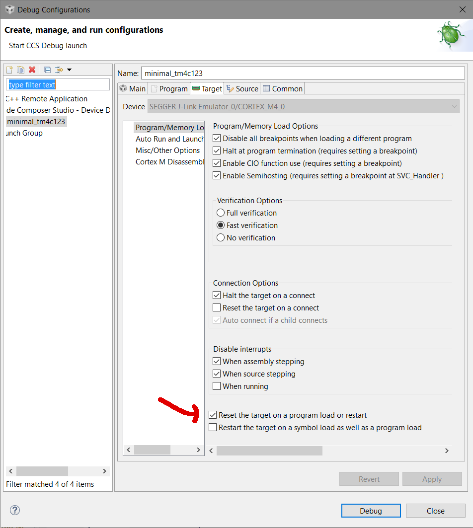
    I went back to the CCS settings, tried a few things, and lo and behold, realized that "Reset the target on a program load or restart" had to be set (see image below).  Looks like my processor was not properly started at the beginning of the debugging session, and hence not properly initialized! Not sure why the default for this option is "disabled"...

    Now the LED blinks just as with the ICDI.

    Point well taken regarding IDEs. And thank you _very_ much for all your help!

  • cb1_mobile said:
    I continue in the belief that (something) w/in CCS is "un-accepting/resistant" to the J-Link - that seems reasonable.

    My friend - did not my post (key content, quoted above) properly detect and identify your likely "NON-J-Link Issue?"     (surely it did!)

    Is it not fair/proper that you award a "This Post Solved my Issue - to my (earlier arriving) highly detailed post - as well?

  • Merci mon ami. (we made a good team - near "instant" back-forth - focus like "laser-beam" - issue resolved!)
    For "giggles" download free "ARM KickStart" (32KB size limit) from IAR. You will NOT go back to "limited/restricted/lesser" fare...