This thread has been locked.

If you have a related question, please click the "Ask a related question" button in the top right corner. The newly created question will be automatically linked to this question.

RTOS/TM4C129ENCZAD: UARTStdioConfig Where is this function documented? What code file defines it?

Part Number: TM4C129ENCZAD

Tool/software: TI-RTOS

I've searched thru all the Tivaware and TiRTOS documents I have found trying to find where the function UARTStdioConfig is defined. I want to know what the first arg field is and what the valid arg values are for it.

If it is not described in any documents, then where is it's code? I saw on anther forum it is supposedly in utils/uartstdio.c. Not in my  install - there is only the following declare in that file:

extern void UARTStdioConfig(uint32_t ui32Port, uint32_t ui32Baud, uint32_t ui32SrcClock);

I was assuming from the arg name, ui32Port, that if I'm using uart port 7, that this arg should be 7. And maybe that is correct???

Some guidance appreciated.

Thank you.

  • Update:
    So the fog finally cleared, the function is in the uartstdio.c file. The following code appears at the start:
    //
    // Check the arguments.
    //
    ASSERT((ui32PortNum == 0) || (ui32PortNum == 1) ||
    (ui32PortNum == 2));

    This suggests that entering a 7 for that arg (as in UART port 7), is not going to work, correct?

    When I step thru this in debug, the program crashes at the following call (at line 365):

    //
    // Enable the UART peripheral for use.
    //
    MAP_SysCtlPeripheralEnable(g_ui32UARTPeriph[ui32PortNum]);

    I assume its the arg value of 7 that I used that is causing this crash.

    Can anyone tell me what the correct approach is to activating UART port 7 (which is wired to a "debug" connector on our board)?

    BTW: UART port -0 (which we are also using) works fine.


    Thank you.

  • Following is the init code for UART 7:

    void InitUART_DebugPort(void)
    {
    ROM_SysCtlPeripheralEnable(SYSCTL_PERIPH_GPIOH);
    ROM_SysCtlPeripheralEnable(SYSCTL_PERIPH_UART7);
    ROM_GPIOPinConfigure(GPIO_PH6_U7RX);
    ROM_GPIOPinConfigure(GPIO_PH7_U7TX);
    ROM_GPIOPinTypeUART(GPIO_PORTH_BASE, GPIO_PIN_6 | GPIO_PIN_7);
    ROM_UARTClockSourceSet(HOST_UART_BASE, UART_CLOCK_PIOSC);
    UARTStdioConfig(7, UART_BAUD_RATE, 16000000);
    }

    where  HOST_UART_BASE       =          UART7_BASE

  • Continued searching forums. Found the following forum discussion on this very issue of how to enable/init ports beyond 0, 1, 2 (from 2014 - kind of ancient...)

    e2e.ti.com/.../1283926

    Bottom line, according to this, user must edit the uart lib files, adding the extra ports beyond the initial 3. I guess this is still the case, 3 years later? Or is there another path I should follow?

    I'm really hesitant to modify vendor lib files - I don't recall ever having to do something like this before.


    Thank you.

  • I modified the uartsdio.c file per the above mentioned forum, adding the missing fields for UART port 7. This gets past the crash. Now the code hangs at line 1278 in file uart.c, which is inside function UARTCharPut:

    //
    // Wait until space is available.
    //
    while(HWREG(ui32Base + UART_O_FR) & UART_FR_TXFF)

    The debugger is stuck at that while loop.

    UARTCharPut is called from a task, from which I want to send calculated 32 bit values (one at a time per transfer, not a continuous stream) to the host PC (running RealTerm), physically connected to UART port 7  via a pin header on our board. Connection is via a USB-rs232 cable. RealTerm shows port is active.

    Scope probes show the RX and TX  lines are pulled high. And of course, nothing is being transmitted from Port 7.

    Stumped again...

  • Erik,

    Are you using TI-RTOS? If so, why don't you just use the UART driver that comes with it instead of using the driverlib calls in TivaWare.

    Todd
  • We started out that way (a few months ago) but that had it's own set of problems. I don't recall the details anymore but something was causing dropped bits in our transmissions via UART0. When we switched to using the TivaC lib, the problem went away.

    Applying this to UART7, appears the UARTCharPut function is hanging. The line of code appears to be waiting for space in the transmit FIFO, if I interpret the comments in the code correctly. Is there possibly some reset I should apply to this port to get it out of what kind of looks like a confused state?

    Thank you for your suggestion.

  • Applied the following function calls at the startup of the task that performs the UART7 transactions:

    UARTDisable(HOST_UART_BASE);
    while(UARTBusy(HOST_UART_BASE))
    {
    }
    UARTEnable(HOST_UART_BASE);

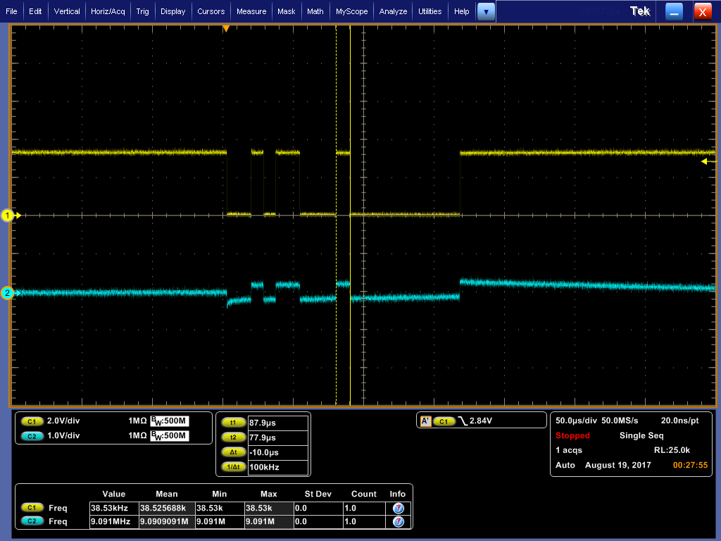
    Now the UARTCharPut no longer hangs and the UART transmits the data out the TX port (scope capture confirms...). However, RealTerm does not show the incoming data. Maybe I don't know how to run RealTerm. However, more troubling, the same bit sequence also appears on the RX pin simultaneously with the TX, but at ~1/4 the V swing.

    Will repeat test with the USB-UART cable disconnected. Will check board traces as well if cable isn't causing. Anything else I should consider?


    Thanks in advance.
  • Hi Erik,

    Looking at the scope capture, are the bit times correct? Can you help me understand the hardware? You have PH6 and PH7 attached to an RS232 transceiver and then the RS232 line attached to an RS232 to USB converter/cable? At which point are you seeing the TX waveform on the RX line?
  • HI Bob,

    There is no RS232 xciever between the uC port and the Gearmo GM-TTL3VT USB-TTL RS232 interface. The GM takes care of the level shift.

    It appears the TXD port on the GM is connected to the TXD port on the uC and both sides are xmitting on that pin. So I need to swap the signal wires on the GM connector to alleviate that.

    Re. timing, the scope captures show bit periods ~9usec. The baud is set to 115200 so I think that is ok.

    I don't recall ever seeing a TXD signal appearing on the RXD line (tho here RXD amplitude is 1/8th TXD) on other UART's I've delt with in the past (ch1 =TXD; ch2 =RXD. Note vertical settings 2V vs 1V). This was captured from the header pins on the board (signal from uC), no UART cable attached. It is identical when captured from the GM cable (doesn't change connected to target or not).

    Both interfaces do this (the uC, and the GM cable, whether connected or not). I need to get back on this and do the cable swap and retest. I submitted a query to GM about the TXD/RXD contention to clarify how they define the direction of these two pins (no reply yet). I think the board designer of our board assumed GM's TXD pin corresponds to target's TXD pin (so direction is transmitting to host). However, appears it is the reverse.

    Any ideas why, after power-up, and initialize, I still have to issue a UART disable/enable to get things working (see previous post)? Is this anything to be concerned about?

    Thank you.

  • The RX signal looks like it is just capacitively (or inductively) coupled from the TX line. This implies that nothing is driving the RX line. I would expect the TX from the Gearmo GM-TTL3VT should connect to the RX of the TM4C, but I will let GM clarify that.