This thread has been locked.

If you have a related question, please click the "Ask a related question" button in the top right corner. The newly created question will be automatically linked to this question.

CCS/TM4C129ENCPDT: ERROR CONNECTING TO TARGET

Part Number: TM4C129ENCPDT
Other Parts Discussed in Thread: SEGGER, TM4C1294NCPDT

Tool/software: Code Composer Studio

I have the kit "Tiva C Series TM4C1294 Connected LaunchPad" which is used to program our new board containing TM4C129ENCPDT, but when trying to program the MCU it is showing as "Error connecting to the target". When we try to program our old board its working fine with same code.

Am also attaching old and new design here.

Error

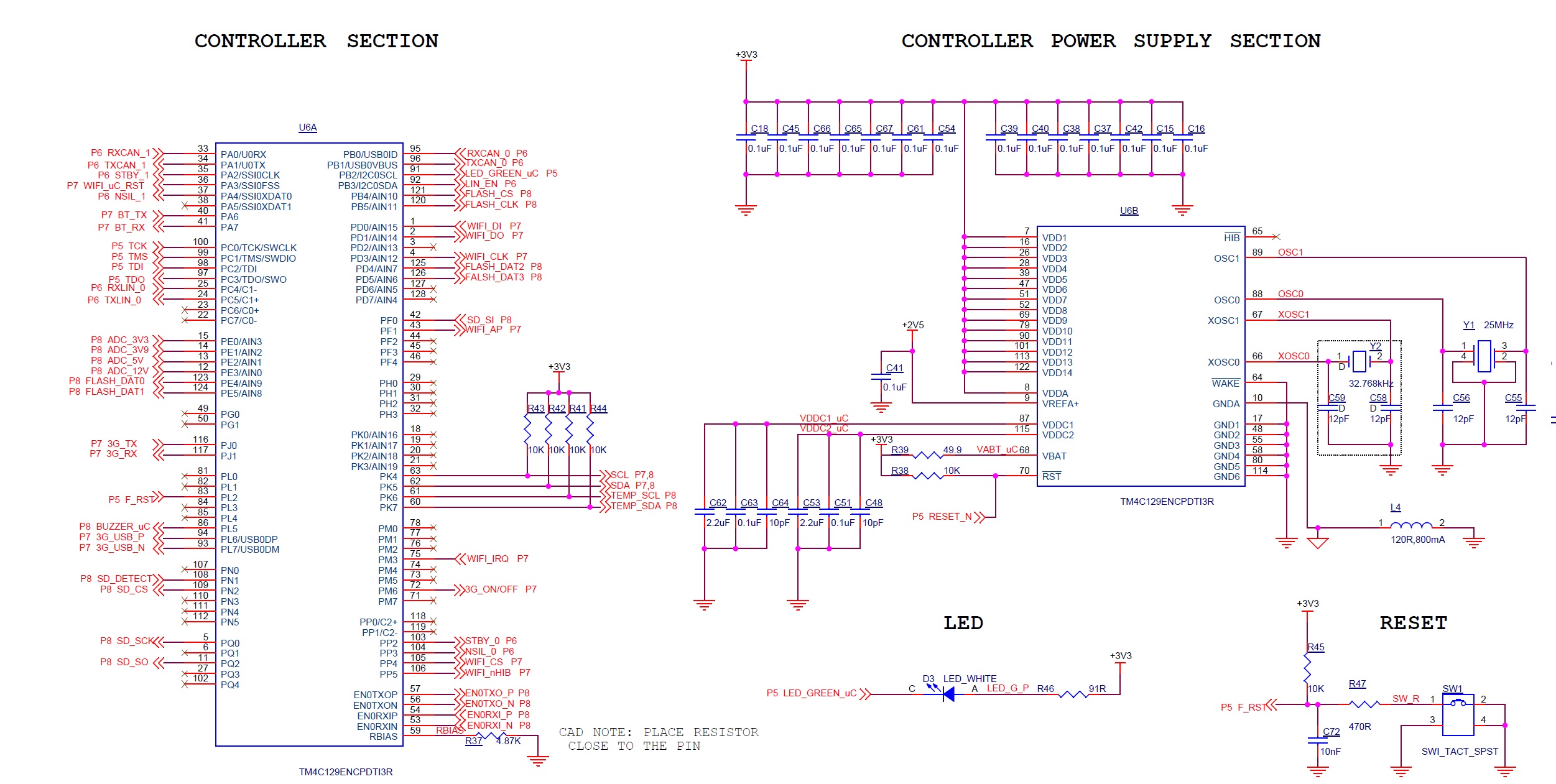
New Design (not programming)

Old Design (programmable)

What seems to be the problem here?

Regards,

Muhsin Ali

  • Feel your pain - such "Failure to Connect" occurs so often, here.     BTW - excellently detailed & presented posting - very well done!

    Both your old & new design - to my eyes - to not include "external pull-up resistors" - which ALWAYS prove helpful. (MCU's internal ones are far too high in value to ALWAYS enable correct JTAG operation - free from rounded signal edges & reflections)

    A superior, multi-vendor (i.e. real) JTAG Probe (i.e. J-Link) also is known for yielding "more robust connections." (the fact that yours "worked once" does not prevent that (past) working from being (then) "marginal" - and (now) inadequate!) Such is reality - low cost "tools" cannot compete against "purpose dedicated ones" - as you/many others - are noting.

    I would check - and compare - the current draw of both boards as well.

    Scope monitoring of the JTAG Signals - first across a "working (old) board" - and then the "failing (new) board" - also is indicated...   (provides the surest "means to correction.")

    Use of a "real/pro/purpose designed JTAG probe" AND inclusion of external pull-up resistors highlights your,  "best path."

  • Check the level on RST, it should be high. Your switch SW1 should be a MON-NO, not a MON-NC.
  • cb1_mobile said:
    Both your old & new design - to my eyes - to not include "external pull-up resistors" - which ALWAYS prove helpful. (MCU's internal ones are far too high in value to ALWAYS enable correct JTAG operation - free from rounded signal edges & reflections)

    Agreed with cb1 here. Also the JTAG connector is not shown, but it should have a de-spiking cap.

    cb1_mobile said:
    A superior, multi-vendor (i.e. real) JTAG Probe (i.e. J-Link) also is known for yielding "more robust connections." (the fact that yours "worked once" does not prevent that (past) working from being (then) "marginal" - and (now) inadequate!) Such is reality - low cost "tools" cannot compete against "purpose dedicated ones" - as you/many others - are noting.

    Absolutely agree.

    I don't like your reset circuit, I'd prefer to see a proper supervisor.  That said a lot of people do use that type.

    And as cb1 usually asks. Have you tried multiple boards?

    Robert

  • As poster reported "first board worked" - is it not (most) likely that Reset Circuit "continued" (i.e. unchanged) and that only poster's "Momentary Switch convention" is flawed?    

    SO very MANY - and SO OFTEN,  "Failures to Connect" - should this not - at some point - be (really) addressed?

    There was, "Time, Effort, Energy" invested to, "Slaughter the "LIKE" - yet (apparently) insufficient time/effort/energy to Address a "Long Known, Disabling, and Disruptive" (Failure to Connect) problem!

  • Hello Bob,

    Level on RST pin is high, the switch is connected to a GPIO pin not to the reset pin.

    Below is the JTAG connector, it is similar for both

    Is there any configuration pin for TM4C129E MCU's (pulling up/down pin's causing some problem's)? 

    Regards,

    Muhsin Ali

  • Hello Cb1,
    Will probe the signals on both the boards. I tried to program 2 new boards, but same issue exists in both.
    Regards,
    Muhsin
  • Hello Robert,

    Yes i tried two new boards, same issue exists. 

    Below is the image for JTAG 

    Is there any configuration pin for TM4C129E MCU's (pulling up/down pin's causing some problem's)? 

    Regards,

    Muhsin Ali

  • Greetings - good that you tried additional boards - testing (only) a single board too often "eats" time/energy.

    My friend - your schematic reveals NO external, pull-up resistors!    Relying upon the "too high" value of the MCU's internal resistors is, "High Risk" - and while may work "sometimes" - it cannot be counted upon!   It should not be too hard to (even temporarily) add external pull-ups - and relaunch your test.

    For a more "in-depth" solution (yet still employing external Rs) - visit "Segger's" site - and investigate the "educational discount" they generously provide for the "World's Top Selling (real) JTAG Probe - "J-Link."     The time/effort/development funds of those here cannot be expected to match those of the "J-Link" - AND it is vendor agnostic - you may use ARM MCUs from "ALL Vendors" - not just a "single vendor" hoping to "lock you in."

    Do make the board current measurement - just in case.     Your scope monitor & capture of (both) good board (accepts JTAG) and bad board (i.e. too often - those here) should prove useful...

  • Hello Muhsin,

    Notice issue 25Mhz crystal (Y1) both PCB are missing a (required) series resistor to limit internal oscillator (MOSC) current draw at a safe level. Note only certain crystal & vendor part numbers are proven & supported this MCU as listed in data sheet. Also perhaps causing some other unreported issues the need for an RBIAS resistor (4.87k/1%) even if not using the EMAC PHY0. RBIAS resistor is often required for the ROM boot loader to function correctly on first POR cycle when flash memory is erased.

    Best of luck!

  • Hello Cb1,
    I will try to program via a J-link.
    I monitor the signals on scope, both new and old board shows different signals while programming same code.
    Regards,
    Muhsin Ali
  • Hello BP101,
    Will try by mounting old crystal's in new board.
    Is the RBIAS resistor really required? anyway will check with mounting a RBIAS resistor.
    Regards,
    Muhsin
  • Indeed - that RBIAS IS required - just as BP noted. (he learned that of course from Amit - who guided so many here)

    Having produced well over 7K boards w/this vendor's MCUs - never have we employed the series (xtal circuit) R - mentioned by BP.    Perhaps there is "extra sensitivity" w/in the 129 series - which we've never used!   (as 200MHz+ M4s - w/DACs - and Graphic Accelerators - far more compellingly -  "dot the Cortex-M landscape!")

    It is surprising that your original (old) board "worked" minus that resistor. As (most) always - vendor's (proper) high-light of such vital requirements REMAINS Lacking.    (yet they've "found the time & will" to "Ban the LIKE!")    Delightful misuse of resources...

  • Muhsin Ali said:
    mounting old crystal's in new board

    More surprising that MOSC is starting proper oscillation without a series resonance (R2k) at OSC1 MCU pin 59. Datasheet warns of damage MOSC/Y1 or both if omitting series resistor. Perhaps cut OSC1 trace chip out small section scrape solder mask with small razor knife tin both sides, solder in R2k SMD. 

  • Normally users tend to, "Follow the example set by Eval/LPads" - when launching their own pcb designs.
    Is it true that ALL such (factory) "129" boards employ that, "xtal ckt, series R?" Such would be telling - would it not?
  • Thank you very much BP, adding RBIAS resistor solves the problem. Now i can program the MCU. But the datasheet mention that resistor is not required when not using PHY.
    Regards,
    Muhsin
  • If you've "not already done so" - you should award a "verify" to poster BP.
    It remains strange that your (earlier) generation of boards were reported to "debug & program" MINUS that resistor!
  • Thank you for your help.
    Adding RBIAS resistor resolves the issue. The old board have a RBIAS resistor, we are using ethernet PHY on that board. The datasheet mention that RBIAS resistor is not required while not using ethernet. We are not using ethernet on our new board, thats why we didnt mount that resistor.
    Regards,
    Muhsin
  • cb1_mobile said:
    Is it true that ALL such (factory) "129" boards employ that, "xtal ckt, series R?" Such would be telling - would it not?

    At least for the '123 the presence and value of a series R is crystal dependent. The purpose of such a resistor is to limit the drive to the crystal. I would expect the '129 would use a similar, if not identical, circuit with similar limitations.

    The '123 user manual lists suggested crystals with suggested series resistors. Note that in some cases the suggested value for Rs is 0 and in others it can go to zero. If the '129 has the same table then I would not recommend using other crystals unless you are experienced. Others will work but you must have an understanding of RF circuitry to properly spec and margin them.

    Robert

  • i already verified BP's post.
    Earlier design have RBIAS resistor
    Regards,
    Muhsin
  • Muhsin Ali said:
    But the datasheet mention that resistor is not required when not using PHY.

    I believe there's an errata on that. If you have not done so than you should go and read the most up to date errata.

    Robert

  • Thank you - glad you resolved - JTAG (or SWD) lock-out - never fun - and happens "far too often here!" (just review the MANY reports of "lock-out!")

    That said - the absence of JTAG pull-up Rs will not serve you well - especially long term. MCU resistors are far too high in value - you may be "marginally performing" now - but: "Aging, Voltage, Temperature change and/or MCU process change" - may again - "Lock you Out!"

    The use of a "real" process-designed JTAG Probe is also (highly) recommended. Low cost (tools?) are NOT your friend - will "cost you" in the long run...
  • Muhsin Ali said:
    Thank you very much BP

    Thank you that verify flag :-)

    To answer CB1 the EK-TM4129XL ships with R2k series resistor and Robert is correct Errata exists around RBIAS. Robert is again correct TM4C1294NCPDT datasheet table lists various R value for different vendor XTALS.

    If using MOSC it might be wise to stick with the datasheet suggested part numbers as some XTALS not listed may have a higher error % and may lead to unexpected software or hardware timing issues. Still suggest cutting the trace with 25Mhz XTAL and add a resistor to eliminate possibility of Y1 drawing excessive current and damaging MOSC silicon over time.

     MCU temperature typically idles around 55-57*C normal as it gets, if temp nears 59-60*C something is likely drawing to much current. 

  • BP101 said:
    MCU temperature typically idles around 55-57*C normal as it gets, if temp nears 59-60*C something is likely drawing to much current. 

    Are not "so many" operating variables (likely) to be "in play" that such a "prescription of temperature range" proves "unsound/questionable?"      Is such MCU temperature - instead - not highly application dependent?    Notably - you've made "NO Allowance" for ambient temperature - which may vary widely - degrading your "hopes/expectations!"

    "Hard rules" - again a "reach" - are NOT "sure" to be universal.     (limited, personal experience proves insufficient - to at all times - be promoted to a "generality!")

  • cb1_mobile said:
    Are not "so many" operating variables (likely) to be "in play"

    Not when Cortex CPU is nearly idle and not processing heavy application tasks.  It would seem likely RBIAS missing excessive current flow would result, you earlier suggested/suspected. Excessive current flow would seemingly elevate CPU temperature well above 57*C, @78*F (ambient) temp yet beyond finger tip touchable (for very long), MCU @62*c.

     Had one launch pad recently out of no where MCU started to over heat to 63*C. Typically @12% CPU load the MCU hardly reaches above 58*C, @78-80*F(ambient). Oddly this bad LP the CPU usage typical 90% under load this day drops from 100% to 10% when finger tip is used to pull heat from the die. That launch pad was connected to IOT server over several days, relative temp 57*C yet jumped to 63*C and application was still running but @100% CPU usage 63*C. 

    A newer launch pad is reporting 10-11% CPU usage 57*C average temp with heavy EMAC0 data load, 6 GPTM counting, 3 PWM generators, 9-10 ADC channels all tasking the advanced peripheral bus.....

    That MCU had been running for 6 months near 57*C 120Mhz and reported 90% CPU usage when EMAC0 was processing data. TI-RTOS kernel load monitor produced similar debug results making it seem as if 90% load was typical. Something was not right in silicon all along and revealed that point especially when MCU started to overheat to 68*C. 

  • BP101 said:
    Not when Cortex CPU is nearly idle and not processing heavy application tasks.

    So then - you have described a "2°C spread" - achieved (only) over a very limited set of operating conditions.     (and still "unbounded" ambient temperatures)

    The value of your "2°C prediction" seems (somehow) highly limited...    And is unlikely to rise to "Generalized Status."

  • cb1_mobile said:
    The value of your "2°C prediction" seems (somehow) highly limited...    

    Referring to 10*c difference 58-68*C (burn finger tip hot). Perhaps the ADC digital temp monitor reading was way off. The IOT global community (3500 launch pads) reported MCU temp ranges in a 3*c area, world wide.

    Odd thing is @68*C the MCU still POR's and runs the application but at 100% CPU usage so it seems MCU temperature can be one way to discover hardware issues. Fact I used to replace 36 pin CMOS controller chips simply by feeling case temp burn finger tip when CPU was not processing. 


    cb1_mobile said:
    (and still "unbounded" ambient temperatures)

    It's bounded 78-80*F ambient but does NOT play into the same range at 70*F ambient, the MCU hangs in low 52*C range.

  • OK, a few points

    First the series resistor in the crystal circuit is there to prevent overdriving the crystal not to prevent damage to the micro.

    Second the damage (and heating) BP describes is strongly suggestive of ESD damage

    Third those temperatures aren't even close to the micro limits. For the '123 (I wouldn't expect the '129 to be dramatically different) The micro is specified to an 85C ambient (ie it will run w/o overheating in an ambient temperature of 85C). In addition it has an abs max Tj of 150C and a recommended Tjmax of 96C. The recommended case temperature max is 93C.

    Pin loads will affect the running current draw and possibly limit the operating temperature further, which is another reason not to drive loads directly.

    Robert

  • Robert Adsett said:
    First the series resistor in the crystal circuit is there to prevent overdriving the crystal

    TM4C1294NCPDT datasheet table 27-23 states ESR 50ohms max for a 25Mhz crystal yet Table 27-24 lists a 25Mhz NDK 70 ohms. So if incorrect crystal is used without a proper RS value it can eventually destroy both the MOSC and the crystal both if the power rating of the OSCPWR is exceeded beyond table 27-23 DL OSCpwr.

    Table 27-24 Notes:

    a. RS values as low as 0 Ohms can be used. Using a lower RS value will result in the WC DL to increase towards the Max DL of the crystal.

    AN: That depends on the specific crystal frequency yet no vendors 25Mhz crystals list RS=0 --- rather RS value of 0.5k-2k ohms.

    f. OSCPWR = (2 * pi * FP * CL * 2.5)2 * ESR / 2. An estimation of the typical power delivered to the crystal is based on the CL,
    FP and ESR parameters of the crystal in the circuit as calculated by the OSCPWR equation. Ensure that the value
    calculated for OSCPWR does not exceed the crystal's drive-level maximum.

    Robert Adsett said:
    Third those temperatures aren't even close to the micro limits.

    Somewhat agree yet MCU can run in an TA 85*c perhaps nearing TJ 125*c @904Mw MAX (industrial type) and the 63*c TJ in an ambient 78*F signals the beginning of the end.

    Perhaps an EMP from fast passing lightning storm night prior. EK129LP was powered via USB hub in stand alone. Hub is powered from an electronic adapter into wall surge protector.

  • BP101 said:
    TM4C1294NCPDT datasheet table 27-23 states ESR 50ohms max for a 25Mhz crystal yet

    BP101 said:
    Table 27-24 lists a 25Mhz NDK 70 ohms

    Yep, Feel free to question TI on the inconsistency.

    BP101 said:
    So if incorrect crystal is used without a proper RS value it can eventually destroy both the MOSC and the crystal both if the power rating of the OSCPWR is exceeded beyond table 27-23 DL OSCpwr.

    Notice that no max power limit is noted for DL. It simply notes the nominal power output. Further from the manual it adds this note for the nominal power

    Manual said:

    f. OSCPWR = (2 * pi * FP * CL * 2.5)2 * ESR / 2. An estimation of the typical power delivered to the crystal is based on the CL, FP and ESR parameters of the crystal in the circuit as calculated by the OSCPWR equation. Ensure that the value calculated for OSCPWR does not exceed the crystal's drive-level maximum.

    Again note that the concern with DL is the crystal limitations.

    BP101 said:
     yet no vendors 25Mhz crystals list RS=0

    No, but several are noted as being able to go to 0, with the limitation that you are approaching the max DL of the crystal. Not clear why you would consider it at all significant that all listed 25MHz crystals have suggested Rs values above 0. That's a function of crystal manufacture as much as frequency, perhaps more.

    Note, I'm not saying there cannot be power limitations for the oscillator. Only that any such limits are not stated and that the primary purpose for Rs in the oscillator circuit is to limit the power the crystal has to dissipate. In fact, the place to explicitly place such limits in the data sheet is notably blank (Except for a note to ensure the crystals parameters are not exceeded). 

    Robert

  • Robert Adsett said:
    Not clear why you would consider it at all significant that all listed 25MHz crystals have suggested Rs values above 0

    Relative to the posters schematics there is not any RS zero or otherwise depicted. Besides TM4c1294NCPDT datasheet recommends engineers source crystals only from vendors listed in these tables. The point of RS value is two fold, not only to protect XTAL but to keep OSC from sourcing to much current by using crystals WC DL value perhaps as an given AMR condition not to be exceeded.

    Who know what will occur over time to the MOSC silicon where no RS value is inserted when it should be, even 0 ohms produces some resistance and notice the lowest table value RS for 25Mhz crystal is 500 ohms. Those listed are good part of the XTAL manufactures on earth where other XTAL retailers may source from an OEM put generic grade markings etc.. 

    Robert Adsett said:
    that the primary purpose for Rs in the oscillator circuit is to limit the power the crystal has to dissipate.

    And to ensure the XTAL even starts oscillation and at the correct frequency.