This thread has been locked.

If you have a related question, please click the "Ask a related question" button in the top right corner. The newly created question will be automatically linked to this question.

TM4C1290NCPDT: PLL Drift/Stability Any Impact to CAN Controller Module

Part Number: TM4C1290NCPDT

Customer running with 25MHz Crystal and trying to determine it's impact TM4C1290NCPDT PLL stability/drift and how it impacts CAN Controller to answer the following:

For PLL's record max drift. If a PLL is being used record tolerance of the PLL and base oscillator

with a 25MHz crystal with the following specification

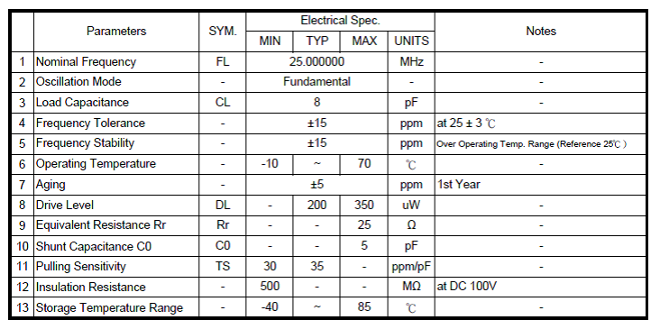
They are worried that based on their calculation there is a 1% drift which violates the CAN protocol of +/- 0.4% at 500K CAN.  The  PLL is configured for 480MHz, M = 96, N = 5, reference frequency 5MHz

  • Hello Lawrence,

    Are they concerned about their crystal selection or the PLL specifications of the TM4C device? If the latter I can say many customers have used 500K or even 1Mbps CAN with external oscillators with success. If the former, perhaps they can share more details (such as what calculations were made?) regarding their concern of the crystal selection?
  • Ralph,

    They are concerned about the PLL specification since there is no information in the datasheet. Is there any information the PLL stability, drift, jitter, etc.

    regards,

    Lawrence
  • Hello Lawrence,

    How about they just use the crystal as the clock source for the CAN bus then? This would probably be ideal to avoid any issues, and would avoid any issues with the 1% PLL drift. I checked with someone more knowledgeable about CAN and he noted that most applications use the crystal as a clock source over the PLL for CAN.

    As far as PLL specs go, I don't know of anything beyond the datasheet on that front.
  • Ralph,

    They will have to make a lot of change their code around since everything is configured for SYSCLK=60MHz so they wanted to avoid that if all possible (since this is a shipping product). There is no option for the CAN to be driven by the crystal directly while the rest of the peripherals remain at 60MHz?
  • Hello Lawrence,

    Have they looked at Section 19.3.15 of the device datasheet?

    This section discusses how to tweak the bit time configurations for the CAN bus and includes the following note: "Because of small variations in frequency caused by changes in temperature or voltage and by deteriorating components, these oscillators are not absolutely stable. As long as the variations remain inside a specific oscillator's tolerance range, the CAN nodes are able to compensate for the different bit rates by periodically resynchronizing to the bit stream."

    This section and the settings discussed may be what they need to feel confidence in the CAN bus at high speeds even with the 1% PLL drift.
  • Ralph,

    I saw that but was not sure how to articulate that, such that it can compensate for the 1% PLL drift or what is the net error/tolerance seen at the pin? Is there any more information or calculation that can be provided? Note the PLL 1% is a number in the datasheet, it was not calculated.
  • Pardon the intrusion - but might this be an issue in which the "Comparison of client's MCU-PLL device specs - against those of (similar) yet competitive others" adds value & confidence.     Should this client have, "Failed to make such effort - and (not) discovered superior performance claims elsewhere" - then it proves likely that they are "complaining" unjustly!    (i.e. complaining for the sake of  "complaining!")

    While past working @ a similar "semi-giant" - we were always charged w/"Outperforming our Market."     If this MCU (your MCU) "near matches" the "general industry performance w/in that PLL category" - the issue likely resolves by default.

    Note that, "State of the Art" rarely reaches to "perfection!"      Matching competitive offerings then - should prove (more than) sufficient...

  • Hi Lawrence,

    Are they referring to this paragraph on page 1579 of the datasheet?

    If the main oscillator provides the clock reference to the PLL, the translation provided by hardware

    and used to program the PLL is available for software in the PLL Frequency n (PLLFREQn) registers

    (see page 285). The internal translation provides a translation within ± 1% of the targeted PLL VCO

    frequency. Table 5-7 on page 231 shows the actual PLL frequency and error for a given crystal

    choice.

    This is not a drift specification. When the PLL is locked, it is constantly adjusting to the oscillator source it is locked to. The overall drift is the drift of the oscillator source. The PLL jitter is actually averaged out over the time of a single CAN bit.

    The statement above is confusing in that it talks about a translation error, but table 5-7 shows only crystal values where the translation error is zero.

  • Bob,

    Yes that is the 1% number they are referencing. Is the translation error dependent on the crystal value/clock source or is it a function of the PLL?

    Regards,

    Lawrence
  • A translation error is dependent on the crystal value.
  • Manual said:

    If the main oscillator provides the clock reference to the PLL, the translation provided by hardware and used to program the PLL is available for software in the PLL Frequency n (PLLFREQn) registers (see page 285). The internal translation provides a translation within ± 1% of the targeted PLL VCO frequency. Table 5-7 on page 231 shows the actual PLL frequency and error for a given crystal choice.

    So this is not a drift but a fixed error. Presumably because of integer divide limitations. I think what you are after is jitter. Specifically the accumulated jitter over a fraction of a bit time. Unfortunately I don't see jitter documented.

    I will comment though, that contrary to the text Table 5-7 (which appears to be repeated in table 26-18) does not provide any error indication that I can see.

    Robert