This thread has been locked.

If you have a related question, please click the "Ask a related question" button in the top right corner. The newly created question will be automatically linked to this question.

TM4C1294NCPDT: Is 5 us Accuracy on Timer using PIOSC Unachievable?

Part Number: TM4C1294NCPDT
Other Parts Discussed in Thread: EK-TM4C1294XL

Hi all,

I am trying to modify a custom board utilizing the TM4C1294NCPDT microcontroller to create trigger source/fan out. The goal of the board is to receive a trigger signal, causing multiple timers (ideally all 6) to start counting which then outputs a signal when they timeout (counter values are updated through an HTTP POST request, therefore a running Ethernet routine in the background).

Software use:

  1. Code Composer Studio 7.1.10
  2. LM Flash Programmer

Hardware use:

  1. EK-TM4C1294XL (debug portion as the debugger/programmer)
  2. Tektronix TDS 2024C Oscilloscope (felt the need to mention this)

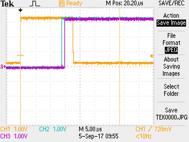
As mentioned above, timers start counting when the user triggers (rising edge input) the board, the purpose of the timers is to create a delay before triggering their respective devices. Right now, I'm attempting to put a 10 us delay in both Timer 4 and Timer 5 using PIOSC as my peripheral clock with no success (where success means that I trigger my devices with a 10 us delay, with little error as possible). The output of my board with the most current code is as follows:

  • Above image is the output of the board, where yellow is the triggering trace
  • The user triggers the LED (rising edge) and Timer 5 (Purple trace) interrupt service routine will turn it off (falling edge) prior to clearing interrupt flag.
  • Blue and purple trace are timer 4 and timer 5 ISR respectively.
  • The trigger trace is 13.40 us wide (from trigger signal to purple ISR routine), blue trace is 600 ns past the falling edge of the trigger (turns on 4 us later than intended), and purple is 1.8 us past the falling edge of the trigger (turns on 5.2 us later than intended).
  • Cursors (dashed yellow lines) in the above image is 10 us wide to show the discrepancy of the time elapsed to entering the ISR.

Timer configuration code is as follows:

void initTimer(void) {

	// Enable all timer module peripherals
	MAP_SysCtlPeripheralEnable(SYSCTL_PERIPH_TIMER0);
	MAP_SysCtlPeripheralEnable(SYSCTL_PERIPH_TIMER4);
	MAP_SysCtlPeripheralEnable(SYSCTL_PERIPH_TIMER5);

	// Enable PIOSC
        MAP_SysCtlAltClkConfig(SYSCTL_ALTCLK_PIOSC);

        // Calibrate PIOSC to ensure best/closest to 16 MHz timer value
        MAP_SysCtlPIOSCCalibrate(SYSCTL_PIOSC_CAL_FACT);

        // Configure Timer peripheral to use PIOSC instead of default (system clock)
	MAP_TimerClockSourceSet(TIMER4_BASE, TIMER_CLOCK_PIOSC);
	MAP_TimerClockSourceSet(TIMER5_BASE, TIMER_CLOCK_PIOSC);

	// Configure Timers into two 16-bit timers in edge time count up mode
	MAP_TimerConfigure(TIMER4_BASE, TIMER_CFG_PERIODIC);
	MAP_TimerConfigure(TIMER5_BASE, TIMER_CFG_PERIODIC);

	// Enable processor interrupts to occur
	MAP_IntMasterEnable();

	// Ensure no pending interrupts occur after enabling the timer interrupts
	MAP_TimerIntClear(TIMER4_BASE, INT_TIMER4A);
	MAP_TimerIntClear(TIMER5_BASE, INT_TIMER5A);
	
	// Enable timer interrupts to occur on timeouts
	MAP_IntEnable(INT_TIMER4A);
	MAP_IntEnable(INT_TIMER5A);
	MAP_TimerIntEnable(TIMER4_BASE, TIMER_TIMA_TIMEOUT);
	MAP_TimerIntEnable(TIMER5_BASE, TIMER_TIMA_TIMEOUT);
}

Trigger Code is as follows:

void PortBIntHandler (void) {

	if (MAP_GPIOIntStatus(GPIO_PORTB_BASE, false) & GPIO_INT_PIN_5) {
		MAP_GPIOIntClear(GPIO_PORTB_BASE, GPIO_INT_PIN_5);

		//uint32_t timerDelayLoad = delay[0] * 120 - 300;	
		//uint32_t timerDelayLoad2 = delay[1] * 120 - 300;

		uint32_t timerDelayLoad1 = delay[0] * 8;
		uint32_t timerDelayLoad2 = delay[1] * 8;

		//MAP_TimerLoadSet(TIMER4_BASE, TIMER_A, delay[0] * 120 - 288);
		//MAP_TimerLoadSet(TIMER5_BASE, TIMER_A, delay[1] * 120 - 308);
		MAP_TimerLoadSet(TIMER4_BASE, TIMER_A, timerDelayLoad1);
		MAP_TimerLoadSet(TIMER5_BASE, TIMER_A, timerDelayLoad2);		
		//HWREG(TIMER4_BASE + TIMER_O_TAILR) = delay[0] * 120;
		//HWREG(TIMER5_BASE + TIMER_O_TAILR) = delay[0] * 120;
		MAP_TimerEnable(TIMER4_BASE, TIMER_A);
		MAP_TimerEnable(TIMER5_BASE, TIMER_A);
		MAP_TimerSynchronize(TIMER0_BASE, (TIMER_4A_SYNC | TIMER_5A_SYNC));
	}
}

Timer Handlers are as follows:

void Timer4IntHandler(void) {
	// Used for debugging purpose only
	MAP_GPIOPinWrite(GPIO_PORTP_BASE, GPIO_PIN_1, 0 << 1);

	// Clear interrupt flag first as
	MAP_TimerIntClear(TIMER4_BASE, TIMER_TIMA_TIMEOUT);

	if (MAP_GPIOPinRead(GPIO_PORTN_BASE, GPIO_PIN_1) != GPIO_PIN_1) {
		MAP_GPIOPinWrite(GPIO_PORTN_BASE, GPIO_PIN_1, 1 << 1);
		MAP_TimerLoadSet(TIMER4_BASE, TIMER_A, 1200000);
	}
	else  if (MAP_GPIOPinRead(GPIO_PORTN_BASE, GPIO_PIN_1) == GPIO_PIN_1) {
		MAP_GPIOPinWrite(GPIO_PORTN_BASE, GPIO_PIN_1, 0 << 1);	
		MAP_TimerDisable(TIMER4_BASE, TIMER_A);
	}
}

void Timer5IntHandler(void) {
	MAP_GPIOPinWrite(GPIO_PORTP_BASE, GPIO_PIN_0, 0);
	MAP_TimerIntClear(TIMER5_BASE, TIMER_TIMA_TIMEOUT);
	
	if (MAP_GPIOPinRead(GPIO_PORTN_BASE, GPIO_PIN_2) != GPIO_PIN_2) {
		MAP_GPIOPinWrite(GPIO_PORTN_BASE, GPIO_PIN_2, 1 << 2);
		MAP_TimerLoadSet(TIMER5_BASE, TIMER_A, 1200000);
	}
	else if (MAP_GPIOPinRead(GPIO_PORTN_BASE, GPIO_PIN_2) == GPIO_PIN_2) {
		MAP_GPIOPinWrite(GPIO_PORTN_BASE, GPIO_PIN_2, 0 << 2);	
		MAP_TimerDisable(TIMER5_BASE, TIMER_A);
	}
}

System Clock is configured as follows:

g_ui32SysClock = MAP_SysCtlClockFreqSet((SYSCTL_XTAL_25MHZ | SYSCTL_OSC_INT | SYSCTL_USE_PLL | SYSCTL_CFG_VCO_480), 120000000);

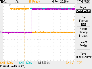
Initially, I used the system clock as the timer source clock, which did come close to the intended delay value, as opposed to the above PIOSC method. However, it was off by at least 1.2 us and  2.4 us (timer 4 and timer 5 respectively) which easily translates to 200 clock cycles on a 120 MHz clock. I thought possibly that the Ethernet code I have running (based on enet_io) was causing the delay, so I figured because the delay had a consistent error that I could subtract this amount of cycles. Unfortunately, this did not have my intended ideal result, but rather it brought the output closer to 10 us inconsistently.

You can see my other attempts to remedy the problem as I have just commented them out (like Direct register programming to reduce clock cycles).

I suppose my question would be - is a 5 us delay even attainable on the timers with an Ethernet Routine running in the background?

Regards,

Stephen B.

I can post more pictures if it helps - I am avoiding making this too lengthy.

  • As your time frames are (relatively) short - and you employed two 16-bit Timers (i.e. split timers) would not your Timer Configure Parameters: "TIMER_CFG_PERIODIC"

    be better served via the (more proper) parameter: "TIMER_CFG_A_PERIODIC"?    (which is intended for "Half-Width" Timers)     The parameter you employed targets "Full-Width" Timers.

    Now - is this sufficient to cause the timed discrepancy you note?    That's (presently) unknown - yet (some) compliance w/TM4C-DRL-UG makes great sense.

    You seem to have created a "small forest" of "interlocking Timers" - which (may) impose chronic timing dependencies!    At this early stage - can this be wise?      Instead - would it not prove "faster, easier, better" to employ just ONE half-width Timer - and attempt to realize your 10µS Timer Delay?      (Kilimanjaro proves "over-challenging" for one's "first climb" - perhaps too - interlocked Timers...)

    I don't readily find any attempt to "prioritize" your most critical Timer Interrupts - these can (effectively) remove, "Timer chained interrupt delays from confounding expectations."     In addition - in compliance w/the always popular (& effective) "KISS" - it proves wise to, "Remove the Ethernet code" - at least till this Timer issue IS resolved.    Further - "Chaining multiple Timers (here) is famed for being "errata laden" - you (have) "Read, understood & complied" (credit "This Old Home") w/latest/greatest vendor errata - for your device - have you not?   (said errata (may) have "suffered" due to the over-arching "need" to mess with the (past) MUCH "LIKED" forum...now a shell of its (former) LIKED self...)

    I have "little" doubt (never say never) that this vendor's Cortex M4 can achieve your objective.    (we've done just that w/multiple (other) vendors' Cortex M0 - a far lesser device!)

    Compliance w/the DRL - followed by another set of measurements - seems worthwhile.     (note too - we have the 30xx version of your scope - believe that "saving scope cap as .png" (not .bmp) enables magnification when opened in a separate tab, here.)    At least - this "had" been the case - prior to the widely heralded - yet ominously "failed" - (yet claimed) forum (LIKE-Less) upgrade...

  • I'm going to start by picking a nit.

    Stephen Bolanos said:
    5 us Accuracy on Timer using PIOSC Unachievable

    That's your subject line, and I would say it's wrong. The PIOSC is +/-10% so as long as you stay withing 50uS then 5uS accuracy is possible. That's not the question you meant to ask but it's one you did and it is an important distinction.

    What you appear to be asking is can I produce a 5uS delay (of some undefined accuracy) when an input arrives?

    The first thing to do is to perform a Rate Monotonic Analysis of your system. It would appear that the highest frequency/lowest latency requirement is this trigger output. If that is the case then

    • The interrupt triggering them should have the highest system priority
    • Nothing should turn off that interrupt. IE no interrupt disable
    • The only task for that interrupt is to set/start the timer that will set the trigger outputs directly (no SW intervention)

    Fortunately the interrupt structure is up to that task since the M4 core has prioritized interrupts and with proper design you can avoid disabling the highest priority interrupt.

    On some micros the timer structure is sufficiently capable that an input on one timer could be used to trigger other timers. I don't think that's the case here but you could check.

    Oh, I'd also use a more accurate timing source that an internal clock like the PIOSC, but that's a minor caveat. +/-10% seems a trifle sloppy w/o having an overriding reason for using it.

    Robert

  • Hi Stephen,

    First like to say CB1 offers great suggestion relative INT priority orders though NVIC interrupt tail chaining might circumvent as the default priority level in the timers sequence interrupts.

    Regarding GPTM-4/5; you set PIOSC as source yet GPTM-0 remains as SYSCLK source. You later synchronize GPTM-4/5 to GPTM-0, don't all 3 timers have to use the same clock source to be synchronous with each other?

    MAP_TimerSynchronize(TIMER0_BASE, (TIMER_4A_SYNC | TIMER_5A_SYNC));

  • Well argued friend/poster BP.     And Robert's "nit-pick" equally well chosen...

    Poster's "gone quiet" (never good) yet his, "Rejection of KISS" forces a steep/uncertain (added difficulty) climb!    (I'd not bet on a successful outcome...)

    Forum & (business) protocol dictates (some) response to trump "silence."    (i.e.  Dear responders - "Up to my ears in alligators - thank you - will respond (maybe) in x (hours, days, months"))

  • Agree silence is not golden.

    Yet researching TM4C1294 datasheet GPTM clock source discovered REG28 feature void in TM4C123G MCU making ALT PIOSC clock source for (GPTM) difficult to achieve @80Mhz SYSCLK. Might be one reason to purchase EK-TM4C1294XL for testing low and high frequency duty cycle signal captures amid forum posts 97 threads deep.

    Read restrictions paragraph several times, ALT bit set then synchronization is key word relative to other timer events of (4*62.5ns+16.6ns=266.6ns) periods or 3.75Mhz minimum time between GPTM synchronous events. Not sure (Thclk) is even as 120Mhz SYSCLK = 8.3ns periods.

  • My friend - do you not (now) direct (very) quiet poster, "Up one of the steeper slopes of Kilimanjaro?"      Even best/brightest schools we engage: MIT; Cal Tech; U of AL, Huntsville; UW-Madison - all highlight the importance & efficiency of "KISS!"

    Poster's combination of the (apparent) desire to "chain Timer interrupts" - minus (any) mention of "Interrupt Priorities" - suggests that "small, measurable, systematic steps" (i.e. "KISS") best able to serve this poster - have been, "kicked to the curb"....     (and not (only) by our poster)

    As always - no support nor justification is provided by poster to justify his "method."      (Crack "helper/rescue crüe" - is thus (nearly) forced to "accept" poster's method - surrendering their creative contributions.)      Such inputs (should) be solicited - forced use of "poster's way" eliminates (much) creative energy - voiding much of any forum's usefulness...

  • Before I reply to any of the above comments, I must deeply apologize for my lack of contact for the past 5 days.

    cb1_mobile said:

    As your time frames are (relatively) short - and you employed two 16-bit Timers (i.e. split timers) would not your Timer Configure Parameters: "TIMER_CFG_PERIODIC"

    be better served via the (more proper) parameter: "TIMER_CFG_A_PERIODIC"?    (which is intended for "Half-Width" Timers)     The parameter you employed targets "Full-Width" Timers.

    Yes, prior to facing this issue, I did attempt the use of Half-Width Timers which, I admit, made more sense and was a far more efficient use of the device. However, at the time I had also implemented Half-Width Timers, with the use of TIMER_CLOCK_SYSTEM (at 120 MHz) as a source, which I had difficulty implementing with a 16-bit timer and prescalar for under 50 us. I figured that I had spent enough time on it, that an attempt at a different method (use of a Full-Wdth Timer) was due. Additionally, a slower system clock could easily have been configured to accommodate but was wary (for lack of justification) of how it will affect Ethernet routines.

    Yet, now with the use of TIMER_CLOCK_PIOSC (at 16 MHz) as a timer source, I realize that I should be able to use Half-Width Timers once more without the need to mess with prescalar (and update the code I shall - after this post. At the very least for comparison and knowledge "level-up").

    Robert Adsett72 said:

    That's your subject line, and I would say it's wrong. The PIOSC is +/-10% so as long as you stay within 50uS then 5uS accuracy is possible. That's not the question you meant to ask but it's one you did and it is an important distinction.

    What you appear to be asking is can I produce a 5uS delay (of some undefined accuracy) when an input arrives?

    I did not intend to state that the MCU was incapable of such a feat; it appears I had forgotten a question mark, but despite that, it still was a poorly worded question. I will keep this in mind next time I choose a subject line. So yes, I am asking if it is possible to produce a 5 uS delay (which I believe I can achieve given the fast clocks I have at my disposal) because I have been (disastrously) unsuccessful in achieving it.

    BP101 said:

    Regarding GPTM-4/5; you set PIOSC as a source yet GPTM-0 remains as SYSCLK source. You later synchronize GPTM-4/5 to GPTM-0, don't all 3 timers have to use the same clock source to be synchronous with each other?

    I did not realize (or know) this was required and have updated my (simpler) code to reflect this correction.

    Robert Adsett72 said:

    The first thing to do is to perform a Rate Monotonic Analysis of your system. It would appear that the highest frequency/lowest latency requirement is this trigger output. If that is the case then

    • The interrupt triggering them should have the highest system priority
    • Nothing should turn off that interrupt. IE no interrupt disable
    • The only task for that interrupt is to set/start the timer that will set the trigger outputs directly (no SW intervention)

    I fail to understand how this will improve the timing discrepancy. I can see that once the trigger occurs, this will disable any Ethernet ISRs to occur in the process of enabling the timers - is this the goal of the prioritizing the trigger over every other ISRs?

    Applying "KISS" (which I did not reject); I removed all the Ethernet routines (and related code) and removed some conditional statements in the timer ISR to reduce time (maybe?) to reduce the amount of "gears" that could cause (potential) errors (applying age-old knowledge that the more gears in a plan have more points of failure).

    This resulted in a curious case where the my LED is turning off after both timers have turned on, despite turning off the LED is the first instruction in the Timer 4 ISR.

    Changing the timer delay value for Timer 5 (purple trace) yields a longer delay as expected, but the LED (yellow trace) stays in the same relative space.

    Apologies cb1_mobile, there were no options to save the images as .png, and instead, I had opted for the .jpeg.

    cb1_mobile said:

    Poster's combination of the (apparent) desire to "chain Timer interrupts" - minus (any) mention of "Interrupt Priorities" - suggests that "small, measurable, systematic steps" (i.e. "KISS"best able to serve this poster - have been, "kicked to the curb"....     (and not (only) by our poster)

    As my replies have shown, my (apparent) lack of knowledge of embedded systems has made me completely miss the idea of prioritizing interrupts, especially, in an interrupt driven system. I feel the need to mention that I do not "kick" help (very, very much appreciated) to the curb and am very open to constructive criticism as I am still learning (aren't we all?). Having said that, I will update the code with this consideration

    Updated, much easier to read code is attached for those interested.

    #include <stdbool.h>
    #include <stdint.h>
    
    #include "inc/hw_ints.h"
    #include "inc/hw_memmap.h"
    #include "inc/hw_timer.h"
    #include "inc/hw_nvic.h"
    
    #include "driverlib/rom.h"
    #include "driverlib/rom_map.h"
    #include "driverlib/gpio.h"
    #include "driverlib/interrupt.h"
    #include "driverlib/pin_map.h"
    #include "driverlib/sysctl.h"
    #include "driverlib/timer.h"
    
    uint32_t systemClock;
    uint32_t pioscClock = 16000000;
    uint32_t delay[2] = {10, 30};
    
    //*****************************************************************************
    //
    // Initialize the two timers and use PIOSC as timer source
    //
    //*****************************************************************************
    void initTimer(void) {
    
    	MAP_SysCtlMOSCConfigSet(SYSCTL_MOSC_HIGHFREQ);
        systemClock = MAP_SysCtlClockFreqSet((SYSCTL_XTAL_25MHZ | SYSCTL_OSC_MAIN | SYSCTL_USE_PLL | SYSCTL_CFG_VCO_480), 120000000);
    
    	// Enable PIOSC
        MAP_SysCtlAltClkConfig(SYSCTL_ALTCLK_PIOSC);
    
    	// Enable all timer module peripherals
    	MAP_SysCtlPeripheralEnable(SYSCTL_PERIPH_TIMER0);
    	MAP_SysCtlPeripheralEnable(SYSCTL_PERIPH_TIMER4);
    	MAP_SysCtlPeripheralEnable(SYSCTL_PERIPH_TIMER5);
    
        // Configure Timer peripheral to use PIOSC instead of default (system clock)
        MAP_TimerClockSourceSet(TIMER0_BASE, TIMER_CLOCK_PIOSC);
    	MAP_TimerClockSourceSet(TIMER4_BASE, TIMER_CLOCK_PIOSC);
    	MAP_TimerClockSourceSet(TIMER5_BASE, TIMER_CLOCK_PIOSC);
    
    	// Configure Timers into two 16-bit timers in edge time count up mode
    	MAP_TimerConfigure(TIMER4_BASE, TIMER_CFG_PERIODIC);
    	MAP_TimerConfigure(TIMER5_BASE, TIMER_CFG_PERIODIC);
    
    	// Enable processor interrupts to occur
    	MAP_IntMasterEnable();
    
    	// Ensure no pending interrupts occur after enabling the timer interrupts
    	MAP_TimerIntClear(TIMER4_BASE, INT_TIMER4A);
    	MAP_TimerIntClear(TIMER5_BASE, INT_TIMER5A);
    	
    	// Out of the three interrupts, Timer 4 is second highest and Timer 5 is third highest
    	MAP_IntPrioritySet(INT_TIMER4A, 0x40);
    	MAP_IntPrioritySet(INT_TIMER5A, 0x80);
    	
    	// Enable timer interrupts to occur on timeouts
    	MAP_IntEnable(INT_TIMER4A);
    	MAP_IntEnable(INT_TIMER5A);
    	MAP_TimerIntEnable(TIMER4_BASE, TIMER_TIMA_TIMEOUT);
    	MAP_TimerIntEnable(TIMER5_BASE, TIMER_TIMA_TIMEOUT);
    }
    
    //*****************************************************************************
    //
    // Initialize all digital pins used in the board.
    //
    //*****************************************************************************
    void initDigital(void) {
    
        // Enables ports that digital pins are attached to
        MAP_SysCtlPeripheralEnable(SYSCTL_PERIPH_GPIOB);
        MAP_SysCtlPeripheralEnable(SYSCTL_PERIPH_GPION);
    	MAP_SysCtlPeripheralEnable(SYSCTL_PERIPH_GPIOP);
    
        // Configure corresponding pins as digital output
        MAP_GPIOPinTypeGPIOInput(GPIO_PORTB_BASE, GPIO_PIN_5);	// Trigger Input diode
    	
    	MAP_GPIOPinTypeGPIOOutput(GPIO_PORTN_BASE, GPIO_PIN_1); // timer 4 output
    	MAP_GPIOPinTypeGPIOOutput(GPIO_PORTN_BASE, GPIO_PIN_2); // timer 5 output
    
    	// For testing only and to provide an easy debounced signal
    	MAP_GPIOPinTypeGPIOOutput(GPIO_PORTP_BASE, GPIO_PIN_1);	// Trigger Output LED
       
    
        // Configure outputs with weak pull-down and output current of up to 4 mA.
        MAP_GPIOPadConfigSet(GPIO_PORTN_BASE, (GPIO_PIN_1 | GPIO_PIN_2), GPIO_STRENGTH_4MA, GPIO_PIN_TYPE_STD_WPD);
    	
    	// Configure trigger pin with weak pull-down and output current of up to 4 mA.
    	MAP_GPIOPadConfigSet(GPIO_PORTP_BASE, GPIO_PIN_1, GPIO_STRENGTH_4MA, GPIO_PIN_TYPE_STD_WPD);
    
        // Trigger Pin input configured to have a weak pull-down to ensure a 0 on the input should there be no inputs
        MAP_GPIOPadConfigSet(GPIO_PORTB_BASE, GPIO_PIN_5, GPIO_STRENGTH_2MA, GPIO_PIN_TYPE_STD_WPU);
        MAP_GPIOIntTypeSet(GPIO_PORTB_BASE, GPIO_PIN_5, GPIO_RISING_EDGE);
        MAP_GPIOIntClear(GPIO_PORTB_BASE, GPIO_INT_PIN_5);
        MAP_IntMasterEnable();
    
        // Enable interrupts to occur on GPIO port B - Only Port P and Q are capable of single pin interrupts
        // In the case of Port B, it has to be checked which pin calls for the service routine as any
        // pins on the port can call for an interrupt if they meet interrupt requirements.
        MAP_GPIOIntEnable(GPIO_PORTB_BASE, GPIO_INT_PIN_5);
    	// Set trigger interrupt as highest priority interrupt so as not to be interrupted until timer enable and sync has occurred.
    	MAP_IntPrioritySet(INT_GPIOB, 0x00);
        MAP_IntEnable(INT_GPIOB);
    	
    	// On restart, ensure that output LEDs are off (and test trigger pin)
    	MAP_GPIOPinWrite(GPIO_PORTN_BASE, GPIO_PIN_1, 0 << 1);
    	MAP_GPIOPinWrite(GPIO_PORTN_BASE, GPIO_PIN_2, 0 << 2);
    	MAP_GPIOPinWrite(GPIO_PORTP_BASE, GPIO_PIN_1, 0 << 1);
    }
    
    //*****************************************************************************
    //
    // Interrupt Handlers for events that occur for Timer 4 and 5
    //
    //******************************************************************************
    void Timer4IntHandler(void) {
    	// Purely for debugging purpose:
    	// Allows for oscilloscope to capture elapsed time from trigger to ISR.
    	MAP_GPIOPinWrite(GPIO_PORTP_BASE, GPIO_PIN_1, 0 << 1);
    
    	MAP_TimerIntClear(TIMER4_BASE, TIMER_TIMA_TIMEOUT);
    	MAP_GPIOPinWrite(GPIO_PORTN_BASE, GPIO_PIN_1, 1 << 1);
    	MAP_TimerDisable(TIMER4_BASE, TIMER_A);
    }
    
    void Timer5IntHandler(void) {
    	// Purely for debugging purpose:
    	// Allows for oscilloscope to capture elapsed time from trigger to ISR.
    	//MAP_GPIOPinWrite(GPIO_PORTP_BASE, GPIO_PIN_1, 0 << 1);
    
    	MAP_TimerIntClear(TIMER5_BASE, TIMER_TIMA_TIMEOUT);	
    	MAP_GPIOPinWrite(GPIO_PORTN_BASE, GPIO_PIN_2, 1 << 2);	
    	MAP_TimerDisable(TIMER5_BASE, TIMER_A);
    }
    
    //*****************************************************************************
    //
    // Interrupt Handler for user input trigger
    //
    //******************************************************************************
    void PortBIntHandler (void) {
    
    	if (MAP_GPIOIntStatus(GPIO_PORTB_BASE, false) & GPIO_INT_PIN_5) {
    		MAP_GPIOIntClear(GPIO_PORTB_BASE, GPIO_INT_PIN_5);
    
    		// Pre-calculate delay using 16 MHz clock
    		uint32_t timerDelayLoad1 = delay[0] * pioscClock/1000000;	
    		uint32_t timerDelayLoad2 = delay[1] * pioscClock/1000000;
    
    		MAP_TimerLoadSet(TIMER4_BASE, TIMER_A, timerDelayLoad1);
    		MAP_TimerLoadSet(TIMER5_BASE, TIMER_A, timerDelayLoad2);		
    		MAP_TimerEnable(TIMER4_BASE, TIMER_A);
    		MAP_TimerEnable(TIMER5_BASE, TIMER_A);
    		MAP_TimerSynchronize(TIMER0_BASE, (TIMER_4A_SYNC | TIMER_5A_SYNC));
    	}
    }
    
    //*****************************************************************************
    //
    // Run asco_valve_test without Ethernet routine to test timer accuracy.
    //
    //*****************************************************************************
    int main(void) {
    
        initDigital();
        initTimer();
    
        MAP_GPIOPinWrite(GPIO_PORTP_BASE, GPIO_PIN_1, 1 << 1); // Trigger
        while(1){}
    }
    

  • Glad you've returned - thanks for your in-depth (and accepting) reply.

    Your new scope caps are larger (easier to read) yet it appears the recent (unwanted) claimed forum "upgrade" has "done away w/the ability to "blow up the image - when opened  in a new tab."    Still - these caps are superior.

    Does it not make sense to (temporarily) employ just one, half-width MCU Timer - and create your 5µS "pulse or delay?"    That serves as a "building block/foundation" - upon which your subsequent efforts land.    Syncing the timers has proved challenging to many - and has fallen victim to errata (be sure to check) - I'd (thus) ask if that's (truly) required by your application.    

    Prioritizing your interrupts deserves your attention & "scope monitored" experimentation.     A newly arriving (higher priority) interrupt (nicely) "kicks a lower priority, executing interrupt" - to the curb.    (lower priority "sits/waits" - until the higher priority executes & completes!)

    Again it appears these are tasks before you:

    • create a single Timer pulse/delay meeting your 5µS spec   (proves that you - and the MCU can (surely) achieve that
    • assign different Timer Interrupt priorities
    • launch a lower priority interrupt - then while it is executing - launch the higher one (and note the higher priority "taking charge").     You may toggle a different GPIO from w/in each Timer Interrupt - which provides a clear & effective means to confirm entry into - and exit from - each unique interrupt
    • lastly - attempt to "chain Timer interrupts" but (only) after solid read & understanding of MCU errata in that specific, "Timer Chained/Interlocked" regard.

    Absences are expected - yet the (responding) guidance given (should) be adopted...    (shows (some) care/concern for your unpaid/overworked/now "LIKE-less" helper crüe...)     We DO look "damn good" in our "low thread count" - vendor supplied - T shirts ... that's for sure...

  • Thank you cb1_mobile, BP101 and Robert Adsett72, your help is always appreciated. 

    Unfortunately, due to some miscommunication between departments, there already exists a solution utilizing the TM4C1294NCPDT and a FPGA to achieve the results I wanted (the FPGA also serves another purpose if you are wondering). 

    While I do not want to abandon the effort I have already put into this (and the help you all have provided), I am being strongly recommended moving onto something else. Personally, a FPGA free solution would benefit the company cost-wise, but unfortunately I also only do what I am told. Needless to say, I'm going to be a rebel and attempt to fix this issue during my spare time (which is rare, with school and work). As a result, I will be replying to this thread hopefully soon until the problem is solved.

    Cheers,

    Stephen B.

  • Poster S.B. "Lack of communication makes for a sad Technologist."

    And too - makes for sad (would be) "helpers." A (sufficient) number of "performance FPGAs" may eliminate the requirement for the MCU - all together!
  • Stephen Bolanos said:
    Personally, a FPGA free solution would benefit the company cost-wise

    Maybe take this opportunity to look at the entire cost of the product. You would save the cost of an FPGA but still may incur cost elsewhere

    • Additional development cost
      • New board
      • New software (as opposed to using existing SW)
      • Costs of test and manufacturing jigs
    • Extra stocking costs
      • stock of multiple boards
      • tracking costs (not insignificant)
    • Training, warranty and maintenance of different boards
    • Opportunity costs. By freeing you up to work on another project the return on that may exceed the extra cost of optimizing the BOM of a new board.
    • Golden screwdrivers. Once developed, it may well be that by making use of the capabilities of the existing hardware you can provide extra capability you can charge for with zero increase in the BOM

    Note that some of these  cost per board figures go down with increased production qty, some will be flat or slightly increasing.

    In some cases the cost of using an existing board can even be negative. Consider the rare case

    • Existing board in stock but no longer in use. Stock exceeds warranty requirement.
    • Limited production run.
    • A reasonable fraction of the existing S/W can be re-purposed.

    Since there is a scrapping cost to the excess boards and the excess boards are valueless the excess boards are, in fact a liability. So using an existing board is not only free but is actually profitable.

    This is a worthwhile exercise to go through and may somewhat alter your view of optimization and build vs. buy.

    Robert

  • *** LIKE *** *** LIKE *** *** LIKE ***

    Absolutely outstanding - substantial display of (both) Engineering & Business acumen - so nicely presented!
    (Presentation counts! this for other than Robert) Take your gf/wife (yet not both, together) to a fine restaurant - presentation "jumps out!"