This thread has been locked.

If you have a related question, please click the "Ask a related question" button in the top right corner. The newly created question will be automatically linked to this question.

TM4C1294NCPDT: Analog Comparator not working properly

Part Number: TM4C1294NCPDT
Other Parts Discussed in Thread: MSP430F2370
Hi there,
I am trying to use tm41294NCPDT Internal analogue Comparator

I am trying to implement Low Power NFC/RFID Card detection Algorithm
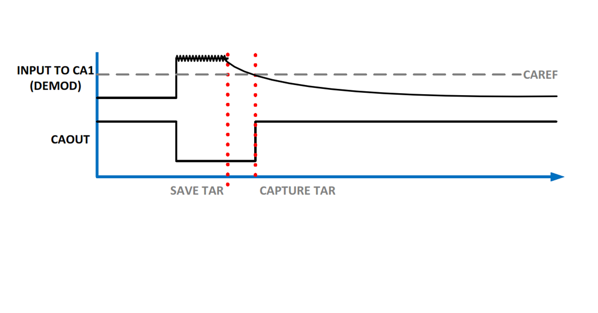
what it does i charge the RC circuit which then discharges and through NFC antenna i read the voltage as soon as it goes down below threshold which in my case i am using 1.65 V (TEST CASE) comparator should generate interrupt

i want to generate following output from Comparator0 using C0+ pin
1:- but the problem is that it triggers interrupt at rising as well as falling edge moreover sometimes it generates interrupt once as soon as the interrupts are configured
2:- I was watching the registers during debugging in IAR and i noticed that instead of comparator 0 register comparator 1 registers are also updating(COMPACSTAT1) but i haven't configured comparator 1
3:- But my main priority is to generate the out put first as shown in figure then trigger an interrupt when comparator output goes back to 1 means interrupt on rising edge


Code is attached below :
Thanks
#include <stdbool.h>
#include <stdint.h>
#include "inc/hw_memmap.h"
#include "driverlib/gpio.h"
#include "driverlib/pin_map.h"
#include "driverlib/pwm.h"
#include "driverlib/sysctl.h"
#include "inc/hw_types.h"
#include "driverlib/debug.h"
#include "driverlib/adc.h"
#include "driverlib/interrupt.h"
#include "driverlib/comp.h"
#include <string.h>
#include "driverlib/uart.h"
#include "utils/uartstdio.h"
#include "driverlib/rom.h"
#include "inc/hw_ints.h"
#include "driverlib/rom_map.h"

uint32_t g_ui32SysClock=120000000;


#ifdef DEBUG
void
__error__(char *pcFilename, uint32_t ui32Line)
{
}
#endif


int x=0;
int status=0;
bool int_status=0;
bool int_status1=0;
int32_t Comp_out = 0;


void COMP_BASE_Interrupt(void)
{
  
  int Comp_out;
  Comp_out = ComparatorValueGet(COMP_BASE, 0);
  
  // ComparatorIntClear(COMP_BASE,0);
  
  //  
  //  bool ulStatus;
  //  ulStatus =ComparatorIntStatus(COMP_BASE, 0, true);
  ComparatorIntClear(COMP_BASE, 0);
  //  ComparatorIntDisable(COMP_BASE,0);
  
  x++;
  
  //      if (status==0)
  //      {
  //        GPIOPinWrite(GPIO_PORTN_BASE, GPIO_PIN_0, 0x1);
  //        status=1;
  //      }
  //      
  //      
  //      if (status==1)
  //      {
  //        GPIOPinWrite(GPIO_PORTN_BASE, GPIO_PIN_0, 0x0);
  //        status=0;
  //      }


}


int main(void)
{
  g_ui32SysClock= SysCtlClockFreqSet((SYSCTL_XTAL_25MHZ |
                                      SYSCTL_OSC_MAIN |
                                        SYSCTL_USE_PLL |
                                          SYSCTL_CFG_VCO_480), 120000000);
  
  int counter=20;
  SysCtlPeripheralEnable(SYSCTL_PERIPH_GPIOF);
  
  
  while ((!SysCtlPeripheralReady(SYSCTL_PERIPH_GPIOF))&&(counter==0))
  {
    counter--;
  }
 
  GPIOPinTypeGPIOOutput(GPIO_PORTF_BASE, GPIO_PIN_4 );
  IntMasterDisable();
  SysCtlPeripheralEnable(SYSCTL_PERIPH_GPIOC);                            //enable port C for negative input
  
  int counter1=20;
  while ((!SysCtlPeripheralReady(SYSCTL_PERIPH_GPIOC))&&(counter1==0))
  {
    counter1--;
  }
  
  SysCtlPeripheralEnable(SYSCTL_PERIPH_GPIOD);                            //enable port D For Output
  
  int counter2=20;
  while ((!SysCtlPeripheralReady(SYSCTL_PERIPH_GPIOD))&&(counter2==0))
  {
    counter2--;
  }
  
  GPIOPinTypeGPIOInput(GPIO_PORTC_BASE, GPIO_PIN_6 );
  GPIOPinTypeGPIOOutput(GPIO_PORTD_BASE, GPIO_PIN_0 );
  
//  GPIOPinWrite(GPIO_PORTD_BASE, GPIO_PIN_0,1);
//  SysCtlDelay(100);
//  GPIOPinWrite(GPIO_PORTD_BASE, GPIO_PIN_0,0);


  SysCtlPeripheralEnable(SYSCTL_PERIPH_COMP0);                                     // enable comparator 1
  int counter3=20;
  while ((!SysCtlPeripheralReady(SYSCTL_PERIPH_COMP0))&&(counter3==0))
  {
    counter3--;
  }
  
  // assign pin type
//GPIOPinTypeComparator(GPIO_PORTC_BASE, GPIO_PIN_7);                    //Analog comparator 1 negative input.
  GPIOPinTypeComparator(GPIO_PORTC_BASE, GPIO_PIN_6);                    //Analog comparator 1 positive input.
  //GPIOPinTypeComparator(GPIO_PORTD_BASE, GPIO_PIN_0);                    //Analog comparator 1 output.
  
  
  //GPIOPinConfigure(GPIO_PIN_4);                                    // pin configure             
  //GPIOPinConfigure(GPIO_PIN_5);                                    //No Need because default function is analogue in 
  
  GPIOPinConfigure(GPIO_PD0_C0O);
  
  
  ComparatorConfigure(COMP_BASE, 0, COMP_TRIG_NONE|COMP_ASRCP_REF 
                      |COMP_INT_FALL | COMP_OUTPUT_NORMAL);                // comparator configure
 
 
  SysCtlDelay(100);
  
  // set internal reference voltage
  ComparatorRefSet(COMP_BASE, COMP_REF_1_65V );
  
  //IntDisable(COMP_BASE);

  ComparatorIntRegister(COMP_BASE,0, COMP_BASE_Interrupt);
  ComparatorIntEnable(COMP_BASE,0);
  //ComparatorIntRegister(COMP_BASE, INT_COMP0);
  //IntEnable(INT_COMP0);
  
  IntMasterEnable();


  //SysCtlDelay(g_ui32SysClock / 96);                                     // delay
  ;
  
  while(1)
  {
    
    
   Comp_out = ComparatorValueGet(COMP_BASE, 0);                            // read comparator output
//    
//    int_status=ComparatorIntStatus(COMP_BASE, 0,true);
//   
//        if (Comp_out==0)
//        {
//          GPIOPinWrite(GPIO_PORTF_BASE, GPIO_PIN_0, 0x0);
//          status=1;
//          SysCtlDelay(1000000);
//        }
//        
//        
//        if (Comp_out==1)
//        {
//          GPIOPinWrite(GPIO_PORTF_BASE, GPIO_PIN_0, 0x1);
//          status=0;
//          SysCtlDelay(1000000);
//        }
    GPIOPinWrite(GPIO_PORTF_BASE, GPIO_PIN_0, 0x1);
    SysCtlDelay(1000);
    GPIOPinWrite(GPIO_PORTF_BASE, GPIO_PIN_0, 0x0);
    SysCtlDelay(1000);    


  }  
}


  • THIS is the reference signal diagram

  • I ant to feed the CO+ pin of the comparater and wait for it to go go below reference voltage upon that generate an interrupt and furthur do my task
  • Have you verified with an oscilloscope that there is no noise on the comparator input that triggers a falling edge when the voltage is rising?
  • I am using the 3 volt output from the board also i have tried using a pin (switching)

    i dont think think that noise is going to be an issue here , isn't it ?

  • Also Can you please make sure that i have the configurations right for my specific case ?
  • Is it possible to use -ve input of comparator as an internal  reference and read data from the positive input 

  • My friend - do you not (both) limit & restrict your options - by using the "internal reference?"    May I suggest - at least during your early design stage - that you employ an "external, adjustable reference."    Firm/I have (always) done this (as we (& clients) find the internal ref "too coarse") and we've (always) succeeded w/MCU's Analog Comparators - both w/LX4F and TM4C123 - using external reference.

    We employed a software driven DAC (standard upon another's ARM MCU) and used that to drive the Ana. Comp's (+) input - forced a set voltage upon the Ana. Comp's (-) pin - "pulled up the Ana. Comp's (output)" and watched that output "switch cleanly from "low to high" as our input signal crossed the "trip point."

    Another advantage of "external reference" is the (better/easier) accommodation of "hysteresis resistors/caps" - should the input signal "linger" at/about the "trip-point."    (i.e. oscillation central...)

    It is our belief that the "internal reference" compromises the analog comparator while adding (another) level of complexity - thus is the most, "likely suspect" in your (thus far) failed attempt...

  • Sir problem is that our design team have already prepared the kit and my only pin availible to read voltage level is PP0 in tm4cNCZAD i-e C2+ while C2- is already busy in other module so my options are limited
  • And that is the problem of, "Premature Commitment" - is it not?

    The "architecture" of the MCU - your selection & choice of key/critical pins is "most everything!"

    If your (existing) "Plan A" is failing - is not "Plan B" (as I've proposed) a reasonable alternative?
    Should not the "design team" be tasked w/this correction? They are the responsible party - are they not?
  • Thanks cb1_mobile 

    You are every bit right but whats done is done and i am looking either i have any options regarding the matter

    One more favor i ask for 

    please fwd me the link to the example code for ULP NFC /RFID implementation Codes

    Thanks 

  • While I'd love to be able to assist further - firm/I are "outsiders" (although interested outsiders) and have LONG observed that vendor makes the, "Search/Find process" for necessary tech data(as you ask) too often - unduly difficult.    

    Firm/I have not used the implementation you seek (ULP NFC /RFID) - thus (your) search would prove as effective as ours.

    Even with your board "done" - it (should) be possible to,

    • switch off the internal reference (via software)
    • feed a variable (proper level) external voltage to your Ana Comp's input
    • possibly add a "pull-up" to the Ana Comp's output   (I cannot recall if that pin will operate in "push-pull" when config'ed as Ana Comp Output)

    These "mods" are not difficult to implement - take little space (use a very small pot) - and DO enable your addition of "hysteresis" (Rs & Cs) to prevent oscillation.

    Again - the adjustment capability offered by the "internal reference" is "STEPPED" - thus limited - and early on we (and our clients) found the steps TOO LARGE for (most all) client applications.

  • Thanks for your concern
  • Hello Tayyab and cb1,

    The application for the NFC ULP card detection only uses a single comparator pin and relies on the Internal reference. Whether this design is perfect is up for debate, but it was certainly possible to be made functional to the extent of meeting application criteria with a single comparator pin and using internal reference when done on an MSP430 so the method is valid at least in that application.

    That said, this application was never tried on TM4C. So whether a single comparator pin is sufficient for TM4C devices is unknown. I would like to assume that it should be fine, but you know what they say about assuming...

    Tayyab, you may want to compare the capabilities of the TM4C comparator and the MSP430F2370 comparator and ensure that the TM4C comparator can meet the requirements outlined in the app note.

    The firmware for the ULP Detection method can be found in the front page of the app note: www.ti.com/.../sloa184.pdf
  • cb1_mobile said:
    And that is the problem of, "Premature Commitment" - is it not?

    *** LIKE LIKE ***

    Not unusually we see similar posts here: "The hardware guys sent me the board like this and..."

    Our experience shows this is a ENORMOUS waste of time. There is probably a bigger size adjective, maybe HUMONGOUS waste of time?

    And then the hardware kit is ready, and the "software guys" are still in the phase of looking for an example code?????

    And of course, in a hurry, because the project is late...

    This ain't no direct criticism to OP here, by all means! It is just embedded development 2-cent discussion on Friday evening. But some sort of Launchpad should always be on the Hello World phase of an embedded project! And while this current post sounds more of a proof of concept than anything else, a simple external signal emulating the sensor should be used. Only when the concept is proven valid (and by then one already has a reasonable program for that purpose), time comes for the hardware guys to come "see what works, and create more specific hardware for the product"...

    Bruno

  • Good post - generally agreed - it DOES appear that poster's HW group "assumed" (or guessed/prayed) - neither famed for effectiveness!

    For those contemplating "real-world use of any MCU's Analog Comparator(s)" - beware of the "savings/convenience" (promised) - yet delivered w/(sometimes) very steep costs!      

    Internal Ana. Comp. references are significantly:

    • limited in number
    • stepped - thus very granular
    • and (maybe) "save one pin"
    • more taxing SW wise to config, set-up, test (i.e. make "right")

    In addition - not always do profit margin & development time (allow) the luxury of such "bit unusual" capability.    A "plain-jane" Ana. Comp. (i.e. all signals/Refs. external) may be "designed & mastered" ONCE - then "Reused REPEATEDLY!"    (investors, clients & development teams LOVE that!)    In addition - if the MCU is "So short of pins that the "Saving of ONE pin" proves so critical" - the (crack) development team has probably made a "sub-optimal" choice - and would SURELY be served best via use of an EXTERNAL Analog Comparator IC!    (gaining those "short sighted" - TWO MCU PINS!)

    Does the choice not resolve to: "One pin" (saving?) which causes:

    • compromised performance
    • unique design (i.e. longer time period to study/master)
    • feature may not (always) be available (especially upon smaller pin count, lower cost devices (such as Cortex M0, or M3)   [both alive, well (thriving) elsewhere]

    MCU's expansion into "Kitchen Sink" role (i.e. Do everything) usually results in "reduced function performance" when compared w/"purpose designed" devices - which are (endlessly) re-usable & "set the standards" for "specific function" performance...

  • One other advantage, external comparators can be wire orred (if you don't choose totem pole outputs) And it's not as if comparators are expensive.

    Robert
  • Oh yes - we've (past) done just that. And - if board space allows a small 14 pin soic - 4 comparators arrive! (for the price of just one!)
    As you know - comparators may also perform basic logic functions: (Or, And & inversion) the ability to EASILY access ALL of the comparator's pins frees it from the (rather severe) limits - portrayed by the lesser (non-ARM) MCU - mentioned here earlier. (i.e. "Save a Pin' - "Lose performance, flexibility & re-use!" ... ... such a deal - step right up, folks!)