


Part Number: TM4C123GH6PM
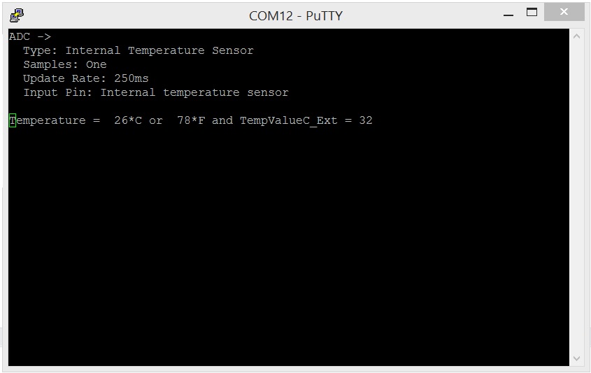
Hi, I want to read internal and external temperature sensors, and display it by using uart. I used the example provided by tivaware, and made some changes. Problem is temperature values is changes continuously. What I mean is temperature value is like 22-24-23-24-22-20-24. I thought maybe the room temperature is on the border between two values but sometimes it jumpes from 20 to 24, also the external temperature behaves same. It is my custom board, and I am using iar. I share code and a screenshot of putty terminal. What might be the problem.
Thanks
Edit: When I heat the external temperature, temperature value increase simultaneously. It shows 40-42-41-44.
//*****************************************************************************
//
// uart_echo.c - Example for reading data from and writing data to the UART in
//               an interrupt driven fashion.
//
// Copyright (c) 2012-2013 Texas Instruments Incorporated.  All rights reserved.
// Software License Agreement
//
// Texas Instruments (TI) is supplying this software for use solely and
// exclusively on TI's microcontroller products. The software is owned by
// TI and/or its suppliers, and is protected under applicable copyright
// laws. You may not combine this software with "viral" open-source
// software in order to form a larger program.
//
// THIS SOFTWARE IS PROVIDED "AS IS" AND WITH ALL FAULTS.
// NO WARRANTIES, WHETHER EXPRESS, IMPLIED OR STATUTORY, INCLUDING, BUT
// NOT LIMITED TO, IMPLIED WARRANTIES OF MERCHANTABILITY AND FITNESS FOR
// A PARTICULAR PURPOSE APPLY TO THIS SOFTWARE. TI SHALL NOT, UNDER ANY
// CIRCUMSTANCES, BE LIABLE FOR SPECIAL, INCIDENTAL, OR CONSEQUENTIAL
// DAMAGES, FOR ANY REASON WHATSOEVER.
//
// This is part of revision 1.0 of the EK-TM4C123GXL Firmware Package.
//
//*****************************************************************************

#include <stdint.h>
#include <stdbool.h>
#include "inc/hw_ints.h"
#include "inc/hw_types.h"
#include "inc/hw_memmap.h"
#include "driverlib/debug.h"
#include "driverlib/fpu.h"
#include "inc/hw_gpio.h"
#include "driverlib/gpio.h"
#include "driverlib/adc.h"
#include "driverlib/interrupt.h"
#include "driverlib/pin_map.h"
#include "driverlib/rom.h"
#include "driverlib/sysctl.h"
#include "driverlib/uart.h"
#include "utils/uartstdio.h"

//*****************************************************************************
//
//! \addtogroup example_list
//! <h1>UART Echo (uart_echo)</h1>
//!
//! This example application utilizes the UART to echo text.  The first UART
//! (connected to the USB debug virtual serial port on the evaluation board)
//! will be configured in 115,200 baud, 8-n-1 mode.  All characters received on
//! the UART are transmitted back to the UART.
//
//*****************************************************************************


//*****************************************************************************
//
// The error routine that is called if the driver library encounters an error.
//
//*****************************************************************************
#ifdef DEBUG
void
__error__(char *pcFilename, uint32_t ui32Line)
{
}
#endif


void GPIOPinUnlockGPIO(uint32_t ui32Port, uint8_t ui8Pins) {
  HWREG(ui32Port + GPIO_O_LOCK) = GPIO_LOCK_KEY;      // Unlock the port
  HWREG(ui32Port + GPIO_O_CR) |= ui8Pins;             // Unlock the Pin
  HWREG(ui32Port + GPIO_O_LOCK) = 0;                  // Lock the port
}


//*****************************************************************************
//
// Send a string to the UART.
//
//*****************************************************************************
void
UARTSend(const uint8_t *pui8Buffer, uint32_t ui32Count)
{
  //
  // Loop while there are more characters to send.
  //
  while(ui32Count--)
  {
    //
    // Write the next character to the UART.
    //
    UARTCharPutNonBlocking(UART2_BASE, *pui8Buffer++);
  }
}

//*****************************************************************************
//
// The UART interrupt handler.
//
//*****************************************************************************
void
UARTIntHandler(void)
{
  uint32_t ui32Status;
  //
  // Get the interrrupt status.
  //
  ui32Status = UARTIntStatus(UART2_BASE, true);

  //
  // Clear the asserted interrupts.
  //
  UARTIntClear(UART2_BASE, ui32Status);

  //
  // Loop while there are characters in the receive FIFO.
  //
  while(UARTCharsAvail(UART2_BASE))
  {
    //
    // Read the next character from the UART and write it back to the UART.
    //
    UARTCharPutNonBlocking(UART2_BASE,UARTCharGetNonBlocking(UART2_BASE));

    SysCtlDelay(SysCtlClockGet() / (1000 * 3));
  }
}

void uart2_init(){
  //initializes UART2
  //sets up transmit and receive interrupts

  //0. Init Clock to UART2 and Port D
  SysCtlPeripheralEnable(SYSCTL_PERIPH_UART2);
  SysCtlPeripheralEnable(SYSCTL_PERIPH_GPIOD);

  //Give it time for clocks to start
  SysCtlDelay(10);

  //Set up AFSEL To D6, D7 and UNLOCK D7
  GPIOPinUnlockGPIO(GPIO_PORTD_BASE, GPIO_PIN_7);
  GPIOPinConfigure(GPIO_PD6_U2RX);
  GPIOPinConfigure(GPIO_PD7_U2TX);
  GPIOPinTypeUART(GPIO_PORTD_BASE, GPIO_PIN_6 | GPIO_PIN_7);

  //set baud rate, txe/rxe, stp2 (clear then and fen), and wlen (8 bit_)
  UARTConfigSetExpClk(UART2_BASE, SysCtlClockGet(), 9600, (UART_CONFIG_WLEN_8 | UART_CONFIG_STOP_ONE | UART_CONFIG_PAR_NONE));

  //        UARTFIFOEnable(UART2_BASE);
  //        UARTTxIntModeSet(UART0_BASE, UART_TXINT_MODE_FIFO);

  //        UARTFIFOLevelSet(UART2_BASE, UART_FIFO_TX1_8, UART_FIFO_RX1_8); //set Rx to trigger with two bytes

  //Enable Global NVIC Interrupt
  IntEnable(INT_UART2);
  //Enable Local Interrupts
  //	UARTIntEnable(UART2_BASE, (UART_INT_TX | UART_INT_RX)); //enable Tx and Rx int
  UARTIntEnable(UART2_BASE, UART_INT_RX | UART_INT_RT);
  UARTIntDisable(UART2_BASE, UART_INT_TX); //disable Tx int
  //Enable UART2
  UARTEnable(UART2_BASE);
  //        UARTFIFODisable(UART2_BASE);
}


void adc0_init(){

  //
  // The ADC0 peripheral must be enabled for use.
  //
  SysCtlPeripheralEnable(SYSCTL_PERIPH_ADC0);
  ROM_SysCtlPeripheralEnable(SYSCTL_PERIPH_GPIOE);
  SysCtlDelay(3);

  GPIOPinTypeADC(GPIO_PORTE_BASE, GPIO_PIN_3);


  //
  // Enable sample sequence 3 with a processor signal trigger.  Sequence 3
  // will do a single sample when the processor sends a singal to start the
  // conversion.  Each ADC module has 4 programmable sequences, sequence 0
  // to sequence 3.  This example is arbitrarily using sequence 3.
  //
  ADCSequenceConfigure(ADC0_BASE, 2, ADC_TRIGGER_PROCESSOR, 0);

  //
  // Configure step 0 on sequence 3.  Sample the temperature sensor
  // (ADC_CTL_TS) and configure the interrupt flag (ADC_CTL_IE) to be set
  // when the sample is done.  Tell the ADC logic that this is the last
  // conversion on sequence 3 (ADC_CTL_END).  Sequence 3 has only one
  // programmable step.  Sequence 1 and 2 have 4 steps, and sequence 0 has
  // 8 programmable steps.  Since we are only doing a single conversion using
  // sequence 3 we will only configure step 0.  For more information on the
  // ADC sequences and steps, reference the datasheet.
  //

  ADCSequenceStepConfigure(ADC0_BASE, 2, 0, ADC_CTL_CH0 );
  ADCSequenceStepConfigure(ADC0_BASE, 2, 1, ADC_CTL_TS | ADC_CTL_IE | ADC_CTL_END);


  //ADCHardwareOversampleConfigure(ADC0_BASE,64);

  //
  // Since sample sequence 3 is now configured, it must be enabled.
  //
  ADCSequenceEnable(ADC0_BASE, 2);

  //
  // Clear the interrupt status flag.  This is done to make sure the
  // interrupt flag is cleared before we sample.
  //
  ADCIntClear(ADC0_BASE, 2);
}


//*****************************************************************************
//
// This example demonstrates how to send a string of data to the UART.
//
//*****************************************************************************
int
main(void)
{
  //
  // Enable lazy stacking for interrupt handlers.  This allows floating-point
  // instructions to be used within interrupt handlers, but at the expense of
  // extra stack usage.
  //
  FPUEnable();
  FPULazyStackingEnable();

  //
  // Set the clocking to run directly from the crystal.
  //
  SysCtlClockSet(SYSCTL_SYSDIV_2_5|SYSCTL_USE_PLL|SYSCTL_OSC_MAIN|SYSCTL_XTAL_16MHZ);

  uart2_init();

  adc0_init();


  //
  // Loop forever echoing data through the UART.
  //


  IntMasterEnable();


  //    UARTSend((uint8_t *)"\033[2JEnter text: ", 16);


  UARTStdioConfig(2, 9600, 80000000);
  //     SysCtlDelay(SysCtlClockGet() / (1000 * 3));
  //
  //
  //     UARTprintf("oldu");

  uint32_t ADCValues[2];

  //
  // These variables are used to store the temperature conversions for
  // Celsius and Fahrenheit.
  //
  uint32_t TempValueC;
  uint32_t TempValueC_Ext;
  uint32_t TempValueF;


  //
  // Display the setup on the console.
  //
  UARTprintf("ADC ->\n");
  UARTprintf("  Type: Internal Temperature Sensor\n");
  UARTprintf("  Samples: One\n");
  UARTprintf("  Update Rate: 250ms\n");
  UARTprintf("  Input Pin: Internal temperature sensor\n\n");


  while(1)
  {

    ADCProcessorTrigger(ADC0_BASE, 2);

    //
    // Wait for conversion to be completed.
    //
    while(!ADCIntStatus(ADC0_BASE, 2, false))
    {
    }

    //
    // Clear the ADC interrupt flag.
    //
    ADCIntClear(ADC0_BASE, 2);

    //
    // Read ADC Value.
    //
    ADCSequenceDataGet(ADC0_BASE, 2, &ADCValues[0]);

    //
    // Use non-calibrated conversion provided in the data sheet. I use floats in intermediate
    // math but you could use intergers with multiplied by powers of 10 and divide on the end
    // Make sure you divide last to avoid dropout.
    //
    TempValueC = (uint32_t)(147.5 - ((75.0*3.3 *(float)ADCValues[1])) / 4096.0);

    TempValueC_Ext = (uint32_t)((((1000*3.3*(float)ADCValues[0]) / 4096.0)-500)/10);


    //
    // Get Fahrenheit value.  Make sure you divide last to avoid dropout.
    //
    TempValueF = ((TempValueC * 9) + 160) / 5;
    //
    // Display the temperature value on the console.
    //
    UARTprintf("Temperature = %3d*C or %3d*F and TempValueC_Ext = %d\r", TempValueC,
               TempValueF,TempValueC_Ext);

    //
    // This function provides a means of generating a constant length
    // delay.  The function delay (in cycles) = 3 * parameter.  Delay
    // 250ms arbitrarily.
    //
    SysCtlDelay(80000000 / 12);
  }
}
