This thread has been locked.

If you have a related question, please click the "Ask a related question" button in the top right corner. The newly created question will be automatically linked to this question.

CCS/TM4C1294NCPDT: TM4C1294

Part Number: TM4C1294NCPDT

Tool/software: Code Composer Studio

Hi,

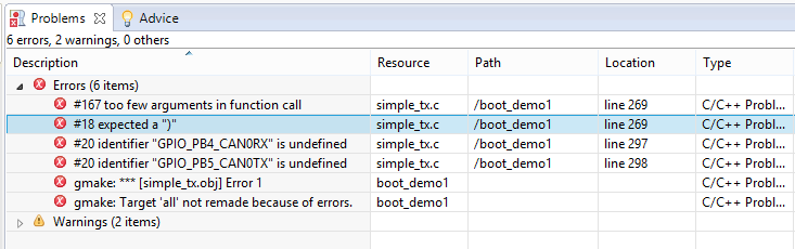
  I am trying to interface CAN in TM4C1294 development board. I have found the CAN example program from the path C:\ti\TivaWare_C_Series-2.1.3.156\examples\peripherals\can. What are the configuration in project or changes to be done in program to build this program. because by copy paste I have tried it a lot and does not get build by going though the procedure in the video Code composer for beginners.

  • Hello Azim,

    In general if you start with a bare CCS project, give it include links to TivaWare DriverLib and then import and add in the example code, you should be most of the way there to getting the project running. I haven't tried to build that particular example yet so there may be another step or two needed, I will try and help you figure that out.

    Edit: I should clarify, when I said 'import' the example code, I had meant using the copy/paste method you have done. You don't need to use an CCS "import" features!

    If are getting build errors, then please post a screen capture of them on E2E. You can do so by clicking "Use rich formatting" and then select the image attachment feature on the toolbar just above the post text box.

    Also please post your main code you are using, as I will want to see what, if any modifications you have done to it. You should do this using "Syntax Highlighter" which can be found under same Rich Formatting toolbar with the symbol "< / >".

  • @Ralph,

    May I note your explanation as, "Quite Good - detailed & covers a variety of (potential) issues." Noted too is the poster's well thought & organized writing - signals his motivation & (proper) request for greater detail.

    Now - especially w/that said - look to his Subject Line: "CCS/TMxyz: TMxyz." Is that of ANY usefulness? (i.e. your response applies equally to ALL TM4C devices - NOT just one!) And - those able & interested to assist this poster - have "NO CLUE" as to what is being sought! None/ZERO!

    Ralph - is this not (another) profound weakness w/the recent "Forum's (claimed yet much disputed) Upgrade?" Such "blind repetition of MCU part number" serves NO Purpose - most always it may IN FACT serve to "Limit the usefulness to follow on readers" who likely may benefit from the thread's content - but either, "Fail to find it" (as they employ a different part no.) or are "turned off" by the "emptiness of thread's subject!"

    We know that you don't "make such flawed rules (claimed) upgrades" - yet they prove damaging - and very much "UNLIKED!"
  • THe example program code is

    //*****************************************************************************

    //

    // simple_tx.c - Example demonstrating simple CAN message transmission.

    //

    // Copyright (c) 2010-2017 Texas Instruments Incorporated.  All rights reserved.

    // Software License Agreement

    //

    //   Redistribution and use in source and binary forms, with or without

    //   modification, are permitted provided that the following conditions

    //   are met:

    //

    //   Redistributions of source code must retain the above copyright

    //   notice, this list of conditions and the following disclaimer.

    //

    //   Redistributions in binary form must reproduce the above copyright

    //   notice, this list of conditions and the following disclaimer in the

    //   documentation and/or other materials provided with the  

    //   distribution.

    //

    //   Neither the name of Texas Instruments Incorporated nor the names of

    //   its contributors may be used to endorse or promote products derived

    //   from this software without specific prior written permission.

    //

    // THIS SOFTWARE IS PROVIDED BY THE COPYRIGHT HOLDERS AND CONTRIBUTORS

    // "AS IS" AND ANY EXPRESS OR IMPLIED WARRANTIES, INCLUDING, BUT NOT

    // LIMITED TO, THE IMPLIED WARRANTIES OF MERCHANTABILITY AND FITNESS FOR

    // A PARTICULAR PURPOSE ARE DISCLAIMED. IN NO EVENT SHALL THE COPYRIGHT

    // OWNER OR CONTRIBUTORS BE LIABLE FOR ANY DIRECT, INDIRECT, INCIDENTAL,

    // SPECIAL, EXEMPLARY, OR CONSEQUENTIAL DAMAGES (INCLUDING, BUT NOT

    // LIMITED TO, PROCUREMENT OF SUBSTITUTE GOODS OR SERVICES; LOSS OF USE,

    // DATA, OR PROFITS; OR BUSINESS INTERRUPTION) HOWEVER CAUSED AND ON ANY

    // THEORY OF LIABILITY, WHETHER IN CONTRACT, STRICT LIABILITY, OR TORT

    // (INCLUDING NEGLIGENCE OR OTHERWISE) ARISING IN ANY WAY OUT OF THE USE

    // OF THIS SOFTWARE, EVEN IF ADVISED OF THE POSSIBILITY OF SUCH DAMAGE.

    //

    // This is part of revision 2.1.4.178 of the Tiva Firmware Development Package.

    //

    //*****************************************************************************

    #include <stdbool.h>

    #include <stdint.h>

    #include "inc/hw_can.h"

    #include "inc/hw_ints.h"

    #include "inc/hw_memmap.h"

    #include "driverlib/can.h"

    #include "driverlib/gpio.h"

    #include "driverlib/interrupt.h"

    #include "driverlib/pin_map.h"

    #include "driverlib/sysctl.h"

    #include "driverlib/uart.h"

    #include "utils/uartstdio.h"

    //*****************************************************************************

    //

    //! \addtogroup can_examples_list

    //! <h1>Simple CAN TX (simple_tx)</h1>

    //!

    //! This example shows the basic setup of CAN in order to transmit messages

    //! on the CAN bus.  The CAN peripheral is configured to transmit messages

    //! with a specific CAN ID.  A message is then transmitted once per second,

    //! using a simple delay loop for timing.  The message that is sent is a 4

    //! byte message that contains an incrementing pattern.  A CAN interrupt

    //! handler is used to confirm message transmission and count the number of

    //! messages that have been sent.

    //!

    //! This example uses the following peripherals and I/O signals.  You must

    //! review these and change as needed for your own board:

    //! - CAN0 peripheral

    //! - GPIO Port B peripheral (for CAN0 pins)

    //! - CAN0RX - PB4

    //! - CAN0TX - PB5

    //!

    //! The following UART signals are configured only for displaying console

    //! messages for this example.  These are not required for operation of CAN.

    //! - GPIO port A peripheral (for UART0 pins)

    //! - UART0RX - PA0

    //! - UART0TX - PA1

    //!

    //! This example uses the following interrupt handlers.  To use this example

    //! in your own application you must add these interrupt handlers to your

    //! vector table.

    //! - INT_CAN0 - CANIntHandler

    //

    //*****************************************************************************

    //*****************************************************************************

    //

    // A counter that keeps track of the number of times the TX interrupt has

    // occurred, which should match the number of TX messages that were sent.

    //

    //*****************************************************************************

    volatile uint32_t g_ui32MsgCount = 0;

    //*****************************************************************************

    //

    // A flag to indicate that some transmission error occurred.

    //

    //*****************************************************************************

    volatile bool g_bErrFlag = 0;

    //*****************************************************************************

    //

    // This function sets up UART0 to be used for a console to display information

    // as the example is running.

    //

    //*****************************************************************************

    void

    InitConsole(void)

    {

       //

       // Enable GPIO port A which is used for UART0 pins.

       // TODO: change this to whichever GPIO port you are using.

       //

       SysCtlPeripheralEnable(SYSCTL_PERIPH_GPIOA);

       //

       // Configure the pin muxing for UART0 functions on port A0 and A1.

       // This step is not necessary if your part does not support pin muxing.

       // TODO: change this to select the port/pin you are using.

       //

       GPIOPinConfigure(GPIO_PA0_U0RX);

       GPIOPinConfigure(GPIO_PA1_U0TX);

       //

       // Enable UART0 so that we can configure the clock.

       //

       SysCtlPeripheralEnable(SYSCTL_PERIPH_UART0);

       //

       // Use the internal 16MHz oscillator as the UART clock source.

       //

       UARTClockSourceSet(UART0_BASE, UART_CLOCK_PIOSC);

       //

       // Select the alternate (UART) function for these pins.

       // TODO: change this to select the port/pin you are using.

       //

       GPIOPinTypeUART(GPIO_PORTA_BASE, GPIO_PIN_0 | GPIO_PIN_1);

       //

       // Initialize the UART for console I/O.

       //

       UARTStdioConfig(0, 115200, 16000000);

    }

    //*****************************************************************************

    //

    // This function provides a 1 second delay using a simple polling method.

    //

    //*****************************************************************************

    void

    SimpleDelay(void)

    {

       //

       // Delay cycles for 1 second

       //

       SysCtlDelay(16000000 / 3);

    }

    //*****************************************************************************

    //

    // This function is the interrupt handler for the CAN peripheral.  It checks

    // for the cause of the interrupt, and maintains a count of all messages that

    // have been transmitted.

    //

    //*****************************************************************************

    void

    CANIntHandler(void)

    {

       uint32_t ui32Status;

       //

       // Read the CAN interrupt status to find the cause of the interrupt

       //

       ui32Status = CANIntStatus(CAN0_BASE, CAN_INT_STS_CAUSE);

       //

       // If the cause is a controller status interrupt, then get the status

       //

       if(ui32Status == CAN_INT_INTID_STATUS)

       {

           //

           // Read the controller status.  This will return a field of status

           // error bits that can indicate various errors.  Error processing

           // is not done in this example for simplicity.  Refer to the

           // API documentation for details about the error status bits.

           // The act of reading this status will clear the interrupt.  If the

           // CAN peripheral is not connected to a CAN bus with other CAN devices

           // present, then errors will occur and will be indicated in the

           // controller status.

           //

           ui32Status = CANStatusGet(CAN0_BASE, CAN_STS_CONTROL);

           //

           // Set a flag to indicate some errors may have occurred.

           //

           g_bErrFlag = 1;

       }

       //

       // Check if the cause is message object 1, which what we are using for

       // sending messages.

       //

       else if(ui32Status == 1)

       {

           //

           // Getting to this point means that the TX interrupt occurred on

           // message object 1, and the message TX is complete.  Clear the

           // message object interrupt.

           //

           CANIntClear(CAN0_BASE, 1);

           //

           // Increment a counter to keep track of how many messages have been

           // sent.  In a real application this could be used to set flags to

           // indicate when a message is sent.

           //

           g_ui32MsgCount++;

           //

           // Since the message was sent, clear any error flags.

           //

           g_bErrFlag = 0;

       }

       //

       // Otherwise, something unexpected caused the interrupt.  This should

       // never happen.

       //

       else

       {

           //

           // Spurious interrupt handling can go here.

           //

       }

    }

    //*****************************************************************************

    //

    // Configure the CAN and enter a loop to transmit periodic CAN messages.

    //

    //*****************************************************************************

    int

    main(void)

    {

    #if defined(TARGET_IS_TM4C129_RA0) ||                                         \

       defined(TARGET_IS_TM4C129_RA1) ||                                         \

       defined(TARGET_IS_TM4C129_RA2)

       uint32_t ui32SysClock;

    #endif

       tCANMsgObject sCANMessage;

       uint32_t ui32MsgData;

       uint8_t *pui8MsgData;

       pui8MsgData = (uint8_t *)&ui32MsgData;

       //

       // Set the clocking to run directly from the external crystal/oscillator.

       // TODO: The SYSCTL_XTAL_ value must be changed to match the value of the

       // crystal on your board.

       //

    #if defined(TARGET_IS_TM4C129_RA0) ||                                         \

       defined(TARGET_IS_TM4C129_RA1) ||                                         \

       defined(TARGET_IS_TM4C129_RA2)

       ui32SysClock = SysCtlClockFreqSet((SYSCTL_XTAL_25MHZ |

                                          SYSCTL_OSC_MAIN |

                                          SYSCTL_USE_OSC)

                                          25000000);

    #else

       SysCtlClockSet(SYSCTL_SYSDIV_1 | SYSCTL_USE_OSC | SYSCTL_OSC_MAIN |

                      SYSCTL_XTAL_16MHZ);

    #endif

       //

       // Set up the serial console to use for displaying messages.  This is

       // just for this example program and is not needed for CAN operation.

       //

       InitConsole();

       //

       // For this example CAN0 is used with RX and TX pins on port B4 and B5.

       // The actual port and pins used may be different on your part, consult

       // the data sheet for more information.

       // GPIO port B needs to be enabled so these pins can be used.

       // TODO: change this to whichever GPIO port you are using

       //

       SysCtlPeripheralEnable(SYSCTL_PERIPH_GPIOB);

       //

       // Configure the GPIO pin muxing to select CAN0 functions for these pins.

       // This step selects which alternate function is available for these pins.

       // This is necessary if your part supports GPIO pin function muxing.

       // Consult the data sheet to see which functions are allocated per pin.

       // TODO: change this to select the port/pin you are using

       //

       GPIOPinConfigure(GPIO_PB4_CAN0RX);

       GPIOPinConfigure(GPIO_PB5_CAN0TX);

       //

       // Enable the alternate function on the GPIO pins.  The above step selects

       // which alternate function is available.  This step actually enables the

       // alternate function instead of GPIO for these pins.

       // TODO: change this to match the port/pin you are using

       //

       GPIOPinTypeCAN(GPIO_PORTB_BASE, GPIO_PIN_4 | GPIO_PIN_5);

       //

       // The GPIO port and pins have been set up for CAN.  The CAN peripheral

       // must be enabled.

       //

       SysCtlPeripheralEnable(SYSCTL_PERIPH_CAN0);

       //

       // Initialize the CAN controller

       //

       CANInit(CAN0_BASE);

       //

       // Set up the bit rate for the CAN bus.  This function sets up the CAN

       // bus timing for a nominal configuration.  You can achieve more control

       // over the CAN bus timing by using the function CANBitTimingSet() instead

       // of this one, if needed.

       // In this example, the CAN bus is set to 500 kHz.  In the function below,

       // the call to SysCtlClockGet() or ui32SysClock is used to determine the

       // clock rate that is used for clocking the CAN peripheral.  This can be

       // replaced with a  fixed value if you know the value of the system clock,

       // saving the extra function call.  For some parts, the CAN peripheral is

       // clocked by a fixed 8 MHz regardless of the system clock in which case

       // the call to SysCtlClockGet() or ui32SysClock should be replaced with

       // 8000000.  Consult the data sheet for more information about CAN

       // peripheral clocking.

       //

    #if defined(TARGET_IS_TM4C129_RA0) ||                                         \

       defined(TARGET_IS_TM4C129_RA1) ||                                         \

       defined(TARGET_IS_TM4C129_RA2)

       CANBitRateSet(CAN0_BASE, ui32SysClock, 500000);

    #else

       CANBitRateSet(CAN0_BASE, SysCtlClockGet(), 500000);

    #endif

       //

       // Enable interrupts on the CAN peripheral.  This example uses static

       // allocation of interrupt handlers which means the name of the handler

       // is in the vector table of startup code.  If you want to use dynamic

       // allocation of the vector table, then you must also call CANIntRegister()

       // here.

       //

       // CANIntRegister(CAN0_BASE, CANIntHandler); // if using dynamic vectors

       //

       CANIntEnable(CAN0_BASE, CAN_INT_MASTER | CAN_INT_ERROR | CAN_INT_STATUS);

       //

       // Enable the CAN interrupt on the processor (NVIC).

       //

       IntEnable(INT_CAN0);

       //

       // Enable the CAN for operation.

       //

       CANEnable(CAN0_BASE);

       //

       // Initialize the message object that will be used for sending CAN

       // messages.  The message will be 4 bytes that will contain an incrementing

       // value.  Initially it will be set to 0.

       //

       ui32MsgData = 0;

       sCANMessage.ui32MsgID = 1;

       sCANMessage.ui32MsgIDMask = 0;

       sCANMessage.ui32Flags = MSG_OBJ_TX_INT_ENABLE;

       sCANMessage.ui32MsgLen = sizeof(pui8MsgData);

       sCANMessage.pui8MsgData = pui8MsgData;

       //

       // Enter loop to send messages.  A new message will be sent once per

       // second.  The 4 bytes of message content will be treated as an uint32_t

       // and incremented by one each time.

       //

       while(1)

       {

           //

           // Print a message to the console showing the message count and the

           // contents of the message being sent.

           //

           UARTprintf("Sending msg: 0x%02X %02X %02X %02X",

                      pui8MsgData[0], pui8MsgData[1], pui8MsgData[2],

                      pui8MsgData[3]);

           //

           // Send the CAN message using object number 1 (not the same thing as

           // CAN ID, which is also 1 in this example).  This function will cause

           // the message to be transmitted right away.

           //

           CANMessageSet(CAN0_BASE, 1, &sCANMessage, MSG_OBJ_TYPE_TX);

           //

           // Now wait 1 second before continuing

           //

           SimpleDelay();

           //

           // Check the error flag to see if errors occurred

           //

           if(g_bErrFlag)

           {

               UARTprintf(" error - cable connected?\n");

           }

           else

           {

               //

               // If no errors then print the count of message sent

               //

               UARTprintf(" total count = %u\n", g_ui32MsgCount);

           }

           //

           // Increment the value in the message data.

           //

           ui32MsgData++;

       }

       //

       // Return no errors

       //

       return(0);

    }

    and found the error as  :

  • Hello azim,

    There are two errors I have identified. The first is that a comma is missing from this API:

       ui32SysClock = SysCtlClockFreqSet((SYSCTL_XTAL_25MHZ |
                                          SYSCTL_OSC_MAIN |
                                          SYSCTL_USE_OSC)
                                          25000000);

    The correct usage is to have a comma after SYSCTL_USE_OSC) as seen here:

       ui32SysClock = SysCtlClockFreqSet((SYSCTL_XTAL_25MHZ |
                                          SYSCTL_OSC_MAIN |
                                          SYSCTL_USE_OSC),
                                          25000000);

    You can find this line easily by double clicking the error for line 269.

    The second issue is what is reported on Lines 297/298 about GPIO_PB4_CAN0RX and GPIO_PB5_CAN0TX. This issue is because the TM4C1294NCPDT which you are using does not have the CAN peripheral on those specific GPIO pins. For CAN0RX and CAN0TX, you will need to use PA0 and PA1 respectively.

  • Thanks amd I could avoid those 2 errors. and still following errors are remaining.  I there any configuration in CCS to be done like adi=ding files, drivers or libraries..?

  • Hello Azim,

    It looks like you have two separate C files with two different main() routines. Please make sure you are excluding files you don't need from your project. My guess is there is a boot_demo1.c file which has a main() routine that isn't related to your attempt to get the CAN example running.