This thread has been locked.

If you have a related question, please click the "Ask a related question" button in the top right corner. The newly created question will be automatically linked to this question.

TM4C1294KCPDT: MCU would be dead after operation solenoid valve

Part Number: TM4C1294KCPDT
Other Parts Discussed in Thread: ULN2003A

Hi Champs,

My customer is designing control board using TM4C1294. And recently they found MCU would jump to hardfault_handler when operating solenoid valve. 

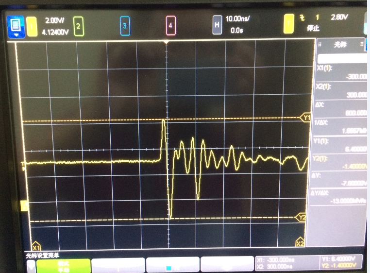
Then we measured the VDD using scope, and found there were some glitch on VDD when operating valve. And reset from RST pin and debugger can recover. And if absorption circuit was added on relay and valve, the probability would be decrease significantly. But still cannot guarantee the issue was solved.

Would you kindly suggest what should we do? I can share the schematics and PCB to you offline.

Thanks.

BR,

Young

  • Switching a current in a large inductor like a solenoid valve causes lots of electrical noise problems. The TM4C will not operate properly if VDD is not maintained within the recommended operating range specified in the datasheet. Proper noise suppression or isolation is required.

    Is the customer using a mechanical relay or a solid state relay?

  • Hi Bob,

    But why PC jumps to Hardfault_handler when operating inductor? And is it possible that someone can help to review their layout?

    Mechanical relay is used.

    Thanks.

    Young

  • Young Hu said:
    But why PC jumps to Hardfault_handler when operating inductor?

    The inductive kickback could cause anything including corrupted instructions, corrupted memory, faulted peripheral or a reset.

    Young Hu said:
    And is it possible that someone can help to review their layout?

    This is fairly conventional stuff, in fact I'd start with the schematic, not the layout.

    First set of questions though, even before that point

    1. Is this relay on the PCB or external?
    2. What is the voltage driving the relay coil?
    3. What is the relay coil's current draw?
    4. How are you driving the relay? Hopefully not direct from the micro's pin.
      1. High side switching or low side?

    Robert

  • Hi,

    Robert Adsett72 said:
    1. Is this relay on the PCB or external?

    Relay is on the PCB;

    Robert Adsett72 said:
    1. What is the voltage driving the relay coil?

    +12V, from AC/DC circuit's transformer.

    Robert Adsett72 said:
    1. What is the relay coil's current draw?

    I need to check.

    Robert Adsett72 said:
    1. How are you driving the relay? Hopefully not direct from the micro's pin.

    ULN2003A is used to drive relay.

    Robert Adsett72 said:
    1. High side switching or low side?

    High side switching.

    Thanks

  • The ULN2003A is NOT intended for "High Side Switching!"    Note that this is a multi-channel, Darlington Transistor Array, capable of far higher currents (~500mA iirc) than any MCU can deliver, and is intended to, "Sink Current" (to Gnd) not "Source Current."    

    This is implemented by connecting one side of the relay's coil to the +12V supply - the remaining coil lead returns to the output side of ULN2003A.    When the MCU drives the mating 2003A input - 2003A's output drives to Gnd - causing the relay coil to "pull in."    The separation between ULN2003A and the relay should be minimal - especially the connection to the relay coil.   And that ULN output, pcb "trace" should NOT come close to any critical MCU signals or elements.

    Usually a diode (of suitable voltage rating (ideally 2-3x that of the relay coil)) placed "across" the relay's coil (electrically) will "limit" the inductive kickback voltage - (always) produced by such relays!    (and the "sure" cause of your client's issue!)

    If this MCU enables, "Slew Rate Control" - lowering the slew rate may prove worthwhile - yet the (standard diode across the relay coil) still - should see use!   

    The diode's cathode ties to +12V (connected to one side of the relay's coil) - and diode's anode to the "switched to Gnd" (remaining) relay contact...   (as the kickback voltage "rises" (causing disturbance) the diode will conduct (when V_kickback exceeds ~12V) which reduces the "disturbance caused by the relay's inductive coil."

    Note - as there are "7 channels" w/in the ULN2003A - it (may) be possible to "employ it" - rather than the "troublesome relay" - to "Switch to Gnd" the (as of yet, undescribed) Load...    And "saving" cost, board space and "unwanted" inductive kickback!     

    (ULN200x series may "parallel their I/O - thus increasing their "current SINKING" capability - and have a "high voltage rating...")  

  • Young Hu said:
    Robert Adsett72
    1. What is the voltage driving the relay coil?

    +12V, from AC/DC circuit's transformer.

    Good this will make protecting easier.

    Young Hu said:
    Robert Adsett72
    1. How are you driving the relay? Hopefully not direct from the micro's pin.

    ULN2003A is used to drive relay.

    Robert Adsett72
    1. High side switching or low side?

    High side switching

    Are you sure? As cb1 says it's designed to switch on the low side and switching on the high side would require floating it. It would also bypass the built-in freewheel diodes.

    There are ways of enhancing that protection and of separating the supplies so inductive noise travelling between power domains is minimized but  the connection of the ULN2003A needs to be addressed first.

    Robert

  • Greetings Robert - as poster and/or client "mis-remembered" (or was that some politician) the operation of any "ULN" - I had to "jump in." (we first used those when the company belonged to "Peter(?) Sprague!")

    It is suspected that the ULN "is" properly connected - yet the relay "must" be large to require (potentially) 5-6W coil current. (12V @ (potentially) ~500mA.)
  • cb1_mobile said:
    It is suspected that the ULN "is" properly connected

    As do I but it should be confirmed so we (us and the designers) don't chase too many ghosts.

    cb1_mobile said:
    yet the relay "must" be large to require (potentially) 5-6W coil current. (12V

    Possible that it's overpowered for the task. it's a reasonably inexpensive device after all.

    Robert

  • It would appear that (both) poster's:

    • MCU "would be dead" ... (that - from Poster's Subject Line)
    • and response (near dead) ... (we might have seen/heard (maybe) ... a "twitch."

    Poster (appears) to desire client's schematic to be held "confidential" - which may prevent "others" from being (similarly) afflicted...     (and good that)

  • Well, it is still the weekend. I'm willing to spot a business day or two before declaring him deceased. Mind you I understand it's a holiday in China, so if the poster is from there it might be a week or so before we hear more.

    Robert
  • Hard to imagine that the simple, "Dear helpers - am "On Holiday" - will deal w/this pesky MCU issue (sometime) ... (maybe) ... when holiday (and post holiday "recovery") conclude!"

    Such response "keeps helpers in the loop..." and is a "show of politeness..."     We are speaking of "death" here - are we not?

  • Hi,

    Really sorry about my careless and rudeness, and I should be killed to death..

    Before 1 weeks' public holiday, we did more testing in customer's lab. And found 2 actions would be effective. Watchdog will recover the MCU from hardfaultHandler. And add film capacitor and resistor between solenoid valve would reduce the failure.

    And it is my fault(misunderstanding) that the ULN2003 should be side switching in their design.

    Please accept my apologies, and thank you so much for your help.
    Regards,
    Young

  • No one wants (nor suggested) your "being killed." (does a, "ploy for sympathy" - arrive?)

    That said - even "on holiday" (especially on holiday) a simple, single sentence, "Thank you - gathering facts - will return "x" days/weeks/months" proves remarkably more effective than "silence." (in the real world - "real clients" are (likely) LOST Forever due to such, "unexplained Silence!")

    You meant to write, "Low Side Switching" via ULN series. (that's the 2nd miscue re: ULN)

    Any absorption and/or lessening of the relay's "inductive kick-back" reduces the impact of that effect. And - as earlier noted - if "Low Side Switching" can be tolerated by the "Relay's Load" - the ULN2003 may REPLACE that "kick-back generator!" (i.e. the relay ... outputs of ULN may be paralleled - adding to its "Switch to Ground, (500mA per output) Current-Sinking capability..."
  • Young Hu said:
    Watchdog will recover the MCU from hardfaultHandler

    That may be true but it doesn't really solve the problem. Instead of halting you are now resetting. The watchdog is not there to cover routine operating conditions such as this.

    Young Hu said:
    And add film capacitor and resistor between solenoid valve would reduce the failure.

    A diode will perform the same task And depending on the situation a diode + zener combination may be even better. This is certainly acceptable if sized correctly though.

    Having said that you should be designing this so you have no failures from this source. Simple reduction is insufficient IMO.

    Young Hu said:
    And it is my fault(misunderstanding) that the ULN2003 should be side switching in their design.

    So they are switching on the low side?

    Robert

  • Greetings Robert - and "indeed" - relying upon the watchdog to "recover" is, "Court of last resort!"    In fact - should the watchdog launch - the "attempted kickback correction" has (likely) proved insufficient and inadequate.   (i.e. FAILED!)

    As noted (earlier) - grasp of the "switching side" (after all this time) continues to "over-challenge."

    The best "proof" of this "fix" would be a, "Fresh set of Scope Caps" - w/scope attached (exactly) as it was previously...   (and offending solenoid, "kicking back")

  • cb1_mobile said:
    The best "proof" of this "fix" would be a, "Fresh set of Scope Caps" - w/scope attached (exactly) as it was previously...   (and offending solenoid, "kicking back")

    Ah-yup.

    And triggered by the control line, not the kickback.

    Robert

  • Hi Robert,

    Watchdog was used to prove MCU was not latched up, and can be recovered. Yes, diode + zener would be a good option, and I will ask customer to have a try. Yes on the low side.

    Many thanks.

    BR,

    Young

  • Hi cb1_mobile,
    Yes, it is low side switching.
    Regards,
    Young