This thread has been locked.

If you have a related question, please click the "Ask a related question" button in the top right corner. The newly created question will be automatically linked to this question.

CCS/TM4C123GH6PM: Problem with timer triggering

Part Number: TM4C123GH6PM
Other Parts Discussed in Thread: SW-DRL

Tool/software: Code Composer Studio

Hi All,

Currently I am facing a problem with ADC input where I am trying to get the input through PE3 which is triggered with timer.

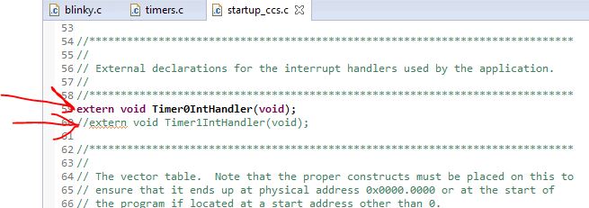
I have built the code without any error though I am not able to trigger the  interrupt. and some more problems are pointed in the attached image.

Any suggestion is appriciated.

#include <stdint.h>
#include <stdbool.h>
#include "inc/hw_ints.h"
#include "driverlib/adc.h"
#include "inc/hw_memmap.h"
#include "inc/hw_types.h"
#include "driverlib/debug.h"
//#include "driverlib/fpu.h"
#include "driverlib/gpio.h"
#include "driverlib/interrupt.h"
#include "driverlib/pin_map.h"
//#include "driverlib/rom.h"
#include "driverlib/sysctl.h"
#include "driverlib/timer.h"
#include "driverlib/uart.h"
#include "utils/uartstdio.h"


float Aquire[1000];
uint32_t ResultIndex = 0;
uint32_t stat;
double fRadians;
float prev = 0;
float strt = 2000;
uint32_t toggler = GPIO_PIN_2;

uint32_t ADC0Value[1];


#ifndef M_PI
#define M_PI 3.14159265358979323846264
#endif


void
InitConsole(void)
{
    //UARTprintf("Console start");
    //
    // Enable GPIO port A which is used for UART0 pins.
    //
    SysCtlPeripheralEnable(SYSCTL_PERIPH_GPIOA);

    //
    // Configure the pin muxing for UART0 functions on port A0 and A1.
    // This step is not necessary if your part does not support pin muxing.
    //
    GPIOPinConfigure(GPIO_PA0_U0RX);
    GPIOPinConfigure(GPIO_PA1_U0TX);

    //
    // Enable UART0 so that we can configure the clock.
    //
    SysCtlPeripheralEnable(SYSCTL_PERIPH_UART0);

    //
    // Use the internal 16MHz oscillator as the UART clock source.
    //
    UARTClockSourceSet(UART0_BASE, UART_CLOCK_PIOSC);

    //
    // Select the alternate (UART) function for these pins.
    //
    GPIOPinTypeUART(GPIO_PORTA_BASE, GPIO_PIN_0 | GPIO_PIN_1);

    //
    // Initialize the UART for console I/O.
    //
    UARTStdioConfig(0,115200,16000000);

    UARTprintf("Console end\n");
}

void
InitADC0(void)
{
    //
    // The ADC0 peripheral must be enabled for use.
    //
    SysCtlPeripheralEnable(SYSCTL_PERIPH_ADC0);

    //
    // For this example ADC0 is used with AIN0 on port E7.
    // The actual port and pins used may be different on your part, consult
    // the data sheet for more information.  GPIO port E needs to be enabled
    // so these pins can be used.
    // TODO: change this to whichever GPIO port you are using.
    //
    SysCtlPeripheralEnable(SYSCTL_PERIPH_GPIOE);

    //
    // Select the analog ADC function for these pins.
    // Consult the data sheet to see which functions are allocated per pin.
    // TODO: change this to select the port/pin you are using.
    //
    GPIOPinTypeADC(GPIO_PORTE_BASE, GPIO_PIN_3);

    //
    // Enable sample sequence 3 with a processor signal trigger.  Sequence 3
    // will do a single sample when the processor sends a signal to start the
    // conversion.  Each ADC module has 4 programmable sequences, sequence 0
    // to sequence 3.  This example is arbitrarily using sequence 3.
    //
    ADCSequenceConfigure(ADC0_BASE, 3, ADC_TRIGGER_PROCESSOR, 0);

    //
    // Configure step 0 on sequence 3.  Sample channel 0 (ADC_CTL_CH0) in
    // single-ended mode (default) and configure the interrupt flag
    // (ADC_CTL_IE) to be set when the sample is done.  Tell the ADC logic
    // that this is the last conversion on sequence 3 (ADC_CTL_END).  Sequence
    // 3 has only one programmable step.  Sequence 1 and 2 have 4 steps, and
    // sequence 0 has 8 programmable steps.  Since we are only doing a single
    // conversion using sequence 3 we will only configure step 0.  For more
    // information on the ADC sequences and steps, reference the datasheet.
    //
    ADCSequenceStepConfigure(ADC0_BASE, 3, 0, ADC_CTL_CH0 | ADC_CTL_IE |
                                 ADC_CTL_END);

    //
    // Since sample sequence 3 is now configured, it must be enabled.
    //
    ADCSequenceEnable(ADC0_BASE, 3);

    //
    // Clear the interrupt status flag.  This is done to make sure the
    // interrupt flag is cleared before we sample.
    //
    ADCIntClear(ADC0_BASE, 3);
    UARTprintf("ADC0 end\n");

}

void
InitGPIO_F(void)
{
    //
    // Enable the GPIO port that is used for the on-board LED.
    //
    SysCtlPeripheralEnable(SYSCTL_PERIPH_GPIOF);
    //
    // Enable the GPIO pins for the LED (PF1 & PF2).
    //
    GPIOPinTypeGPIOOutput(GPIO_PORTF_BASE, GPIO_PIN_2);

    UARTprintf("GPIOEnabled\n");

}
void
InitTimer(void)
{
    // Enable the peripherals used by this example.
    //
    SysCtlPeripheralEnable(SYSCTL_PERIPH_TIMER0);
    //SysCtlPeripheralEnable(SYSCTL_PERIPH_TIMER1);

    //
    // Enable processor interrupts.
    //
    IntMasterEnable();

    //tickk = SysCtlClockGet();
    //
    // Configure the two 32-bit periodic timers.
    //
    TimerConfigure(TIMER0_BASE, TIMER_CFG_PERIODIC);
    //ROM_TimerConfigure(TIMER1_BASE, TIMER_CFG_PERIODIC);
    TimerLoadSet(TIMER0_BASE, TIMER_A, SysCtlClockGet());
    //ROM_TimerLoadSet(TIMER1_BASE, TIMER_A, ROM_SysCtlClockGet() / 2);

    //
    // Setup the interrupts for the timer timeouts.
    //
    IntEnable(INT_TIMER0A);
    //ROM_IntEnable(INT_TIMER1A);
    TimerIntEnable(TIMER0_BASE, TIMER_TIMA_TIMEOUT);
    //ROM_TimerIntEnable(TIMER1_BASE, TIMER_TIMA_TIMEOUT);

    //
    // Enable the timers.
    //
    TimerEnable(TIMER0_BASE, TIMER_A);
    //ROM_TimerEnable(TIMER1_BASE, TIMER_A);

    UARTprintf("TimerEnabled\n");
}
//*****************************************************************************
//
// The interrupt handler for the first timer interrupt.
//
//*****************************************************************************
void
Timer0IntHandler(void)
{
    UARTprintf("Timer start\n");

    TimerIntClear(TIMER0_BASE, TIMER_TIMA_TIMEOUT);

    toggler ^= GPIO_PIN_2;

    UARTprintf("Toggler = %3d\n",toggler);

    GPIOPinWrite(GPIO_PORTF_BASE, GPIO_PIN_2,toggler);

    UARTprintf("bulb\n");


    ADCIntClear(ADC0_BASE, 3);
    UARTprintf("ADCClear\n");

    ADCProcessorTrigger(ADC0_BASE, 3);
    UARTprintf("ProTrig\n");

    while(!ADCIntStatus(ADC0_BASE, 3, false))
    {
        UARTprintf("G\r");
    }

    ADCIntClear(ADC0_BASE, 3);
    UARTprintf("ADCClear\n");

    ADCSequenceDataGet(ADC0_BASE, 3, ADC0Value);
    UARTprintf("GetData\n");
    //UARTprintf("%3d\n",ADC0Value[0]);

    UARTprintf("%3d\n",ADC0Value[0]);
    if (prev-ADC0Value[0]>strt)
    {
        if(stat==0)
            {
                if(ResultIndex<900)
                {
                    Aquire[ResultIndex] = ADC0Value[0];
                    ResultIndex+=1;
                }
                else
                {
                    stat = 1;
                }
            }
    }
    else
    {
        prev = ADC0Value[0];
    }


    IntMasterDisable();

    IntMasterEnable();
}


int main(void)
{

    //FPULazyStackingEnable();
    //FPUEnable();

    //SysCtlClockSet(SYSCTL_SYSDIV_1 | SYSCTL_USE_PLL | SYSCTL_XTAL_16MHZ | SYSCTL_OSC_MAIN);
    //SysCtlClockSet(SYSCTL_SYSDIV_1 | SYSCTL_USE_OSC | SYSCTL_OSC_MAIN | SYSCTL_XTAL_16MHZ);
    SysCtlClockSet(SYSCTL_SYSDIV_2_5|SYSCTL_USE_PLL|SYSCTL_OSC_MAIN|SYSCTL_XTAL_16MHZ);

    //
    // Initialize the UART and write status.
    //
    InitConsole();

    //
    // Initialize the ADC0.
    //
    InitADC0();

    InitGPIO_F();

    //
    // Initialize the Timer for triggering.
    //
    InitTimer();


    while(1)
    {
        
    }
}

  • Rohan Chawhan said:
    I have built the code without any error though I am not able to trigger the  interrupt

    And

    Rohan Chawhan said:

    ADCSequenceConfigure(ADC0_BASE, 3, ADC_TRIGGER_PROCESSOR, 0);

       You may DIRECTLY Trigger the ADC from the Timer!    (employ parameter, "ADC_TRIGGER_TIMERinstead)

    And

    Rohan Chawhan said:

    Timer0IntHandler(void)

    {

    UARTprintf("Timer start\n");

    TimerIntClear(TIMER0_BASE, TIMER_TIMA_TIMEOUT);

    toggler ^= GPIO_PIN_2;

    .

    .

    ADCProcessorTrigger(ADC0_BASE, 3);

        "ADCProcessorTrigger()"   This proves both indirect & superfluous!   (see direct method - above)

  • //*****************************************************************************
    //
    // timers.c - Timers example.
    //
    // Copyright (c) 2012-2016 Texas Instruments Incorporated.  All rights reserved.
    // Software License Agreement
    // 
    // Texas Instruments (TI) is supplying this software for use solely and
    // exclusively on TI's microcontroller products. The software is owned by
    // TI and/or its suppliers, and is protected under applicable copyright
    // laws. You may not combine this software with "viral" open-source
    // software in order to form a larger program.
    // 
    // THIS SOFTWARE IS PROVIDED "AS IS" AND WITH ALL FAULTS.
    // NO WARRANTIES, WHETHER EXPRESS, IMPLIED OR STATUTORY, INCLUDING, BUT
    // NOT LIMITED TO, IMPLIED WARRANTIES OF MERCHANTABILITY AND FITNESS FOR
    // A PARTICULAR PURPOSE APPLY TO THIS SOFTWARE. TI SHALL NOT, UNDER ANY
    // CIRCUMSTANCES, BE LIABLE FOR SPECIAL, INCIDENTAL, OR CONSEQUENTIAL
    // DAMAGES, FOR ANY REASON WHATSOEVER.
    // 
    // This is part of revision 2.1.3.156 of the EK-TM4C123GXL Firmware Package.
    //
    //*****************************************************************************
    
    #include <stdint.h>
    #include <stdbool.h>
    #include "inc/hw_ints.h"
    #include "inc/hw_memmap.h"
    #include "inc/hw_types.h"
    #include "driverlib/debug.h"
    #include "driverlib/adc.h"
    #include "driverlib/fpu.h"
    #include "driverlib/gpio.h"
    #include "driverlib/interrupt.h"
    #include "driverlib/pin_map.h"
    #include "driverlib/rom.h"
    #include "driverlib/sysctl.h"
    #include "driverlib/timer.h"
    #include "driverlib/uart.h"
    #include "utils/uartstdio.h"
    
    //*****************************************************************************
    //
    //! \addtogroup example_list
    //! <h1>Timer (timers)</h1>
    //!
    //! This example application demonstrates the use of the timers to generate
    //! periodic interrupts.  One timer is set up to interrupt once per second and
    //! the other to interrupt twice per second; each interrupt handler will toggle
    //! its own indicator on the display.
    //!
    //! UART0, connected to the Virtual Serial Port and running at 115,200, 8-N-1,
    //! is used to display messages from this application.
    //
    //*****************************************************************************
    
    //*****************************************************************************
    //
    // Flags that contain the current value of the interrupt indicator as displayed
    // on the UART.
    //
    //*****************************************************************************
    uint32_t g_ui32Flags;
    float Aquire[1000];
    uint32_t ResultIndex = 0;
    uint32_t stat;
    
    float prev = 0;
    float strt = 2000;
    
    uint32_t ADC0Value[1];
    
    //*****************************************************************************
    //
    // The Function for the Enable ADC0
    //
    //*****************************************************************************
    void
    InitADC0(void)
    {
        //
        // The ADC0 peripheral must be enabled for use.
        //
        SysCtlPeripheralEnable(SYSCTL_PERIPH_ADC0);
    
        //
        // For this example ADC0 is used with AIN0 on port E7.
        // The actual port and pins used may be different on your part, consult
        // the data sheet for more information.  GPIO port E needs to be enabled
        // so these pins can be used.
        // TODO: change this to whichever GPIO port you are using.
        //
        SysCtlPeripheralEnable(SYSCTL_PERIPH_GPIOE);
    
        //
        // Select the analog ADC function for these pins.
        // Consult the data sheet to see which functions are allocated per pin.
        // TODO: change this to select the port/pin you are using.
        //
        GPIOPinTypeADC(GPIO_PORTE_BASE, GPIO_PIN_3);
    
        //
        // Enable sample sequence 3 with a processor signal trigger.  Sequence 3
        // will do a single sample when the processor sends a signal to start the
        // conversion.  Each ADC module has 4 programmable sequences, sequence 0
        // to sequence 3.  This example is arbitrarily using sequence 3.
        //
        ADCSequenceConfigure(ADC0_BASE, 3, ADC_TRIGGER_TIMER, 0);
    
        //
        // Configure step 0 on sequence 3.  Sample channel 0 (ADC_CTL_CH0) in
        // single-ended mode (default) and configure the interrupt flag
        // (ADC_CTL_IE) to be set when the sample is done.  Tell the ADC logic
        // that this is the last conversion on sequence 3 (ADC_CTL_END).  Sequence
        // 3 has only one programmable step.  Sequence 1 and 2 have 4 steps, and
        // sequence 0 has 8 programmable steps.  Since we are only doing a single
        // conversion using sequence 3 we will only configure step 0.  For more
        // information on the ADC sequences and steps, reference the datasheet.
        //
        ADCSequenceStepConfigure(ADC0_BASE, 3, 0, ADC_CTL_CH0 | ADC_CTL_IE |
                                     ADC_CTL_END);
    
        //
        // Since sample sequence 3 is now configured, it must be enabled.
        //
        ADCSequenceEnable(ADC0_BASE, 3);
    
        //
        // Clear the interrupt status flag.  This is done to make sure the
        // interrupt flag is cleared before we sample.
        //
        ADCIntClear(ADC0_BASE, 3);
        UARTprintf("ADC0 end\n");
    
    }
    
    //*****************************************************************************
    //
    // The function for the LED Enable.
    //
    //*****************************************************************************
    
    void
    InitGPIO_F(void)
    {
        //
        // Enable the GPIO port that is used for the on-board LED.
        //
        SysCtlPeripheralEnable(SYSCTL_PERIPH_GPIOF);
        //
        // Enable the GPIO pins for the LED (PF1 & PF2).
        //
        GPIOPinTypeGPIOOutput(GPIO_PORTF_BASE, GPIO_PIN_2);
    
        UARTprintf("GPIOEnabled\n");
    
    }
    
    void
    InitTimer0(void)
    {
        //
        // Enable the peripherals used by this example.
        //
        SysCtlPeripheralEnable(SYSCTL_PERIPH_TIMER0);
    
        //
        // Enable processor interrupts.
        //
        IntMasterEnable();
    
        //
        // Configure the two 32-bit periodic timers.
        //
        TimerConfigure(TIMER0_BASE, TIMER_CFG_PERIODIC);
        TimerLoadSet(TIMER0_BASE, TIMER_A, SysCtlClockGet());
    
        // Enable triggering
        TimerControlTrigger(TIMER0_BASE, TIMER_A, true);
    
        //
        // Setup the interrupts for the timer timeouts.
        //
        //IntEnable(INT_TIMER0A);
        //TimerIntEnable(TIMER0_BASE, TIMER_TIMA_TIMEOUT);
    
        //
        // Enable the timers.
        //
        TimerEnable(TIMER0_BASE, TIMER_A);
    
        UARTprintf("TimerEnabled\n");
    }
    
    //*****************************************************************************
    //
    // The interrupt handler for the first timer interrupt.
    //
    //*****************************************************************************
    void
    Timer0IntHandler(void)
    {
    
        UARTprintf("TimerHandlerStart\n");
    
        //
        // Clear the timer interrupt.
        //
        TimerIntClear(TIMER0_BASE, TIMER_TIMA_TIMEOUT);
    
        //
        // Toggle the flag for the first timer.
        //
        HWREGBITW(&g_ui32Flags, 0) ^= 1;
    
        //
        // Use the flags to Toggle the LED for this timer
        //
        GPIOPinWrite(GPIO_PORTF_BASE, GPIO_PIN_1, g_ui32Flags << 1);
    
        ADCIntClear(ADC0_BASE, 3);
        //UARTprintf("ADCClear\n");
    
        //ADCProcessorTrigger(ADC0_BASE, 3);
        //UARTprintf("ProTrig\n");
    
        while(!ADCIntStatus(ADC0_BASE, 3, false))
        {
            UARTprintf("G\r");
        }
    
        ADCIntClear(ADC0_BASE, 3);
        //UARTprintf("ADCClear\n");
    
        ADCSequenceDataGet(ADC0_BASE, 3, ADC0Value);
        //UARTprintf("GetData\n");
        //UARTprintf("%3d\n",ADC0Value[0]);
    
        UARTprintf("%3d\n",ADC0Value[0]);
        if (prev-ADC0Value[0]>strt)
        {
            if(stat==0)
            {
                if(ResultIndex<900)
                {
                    Aquire[ResultIndex] = ADC0Value[0];
                    ResultIndex+=1;
                }
                else
                {
                    stat = 1;
                }
            }
        }
        else
        {
            prev = ADC0Value[0];
        }
    
        //
        // Update the interrupt status on the display.
        //
        IntMasterDisable();
        
        IntMasterEnable();
        
        UARTprintf("TimerHandlerEnd\n");
    }
    
    
    //*****************************************************************************
    //
    // Configure the UART and its pins.  This must be called before UARTprintf().
    //
    //*****************************************************************************
    void
    ConfigureUART(void)
    {
        //
        // Enable the GPIO Peripheral used by the UART.
        //
        SysCtlPeripheralEnable(SYSCTL_PERIPH_GPIOA);
    
        //
        // Enable UART0
        //
        SysCtlPeripheralEnable(SYSCTL_PERIPH_UART0);
    
        //
        // Configure GPIO Pins for UART mode.
        //
        GPIOPinConfigure(GPIO_PA0_U0RX);
        GPIOPinConfigure(GPIO_PA1_U0TX);
        GPIOPinTypeUART(GPIO_PORTA_BASE, GPIO_PIN_0 | GPIO_PIN_1);
    
        //
        // Use the internal 16MHz oscillator as the UART clock source.
        //
        UARTClockSourceSet(UART0_BASE, UART_CLOCK_PIOSC);
    
        //
        // Initialize the UART for console I/O.
        //
        UARTStdioConfig(0, 115200, 16000000);
    }
    
    //*****************************************************************************
    //
    // This example application demonstrates the use of the timers to generate
    // periodic interrupts.
    //
    //*****************************************************************************
    int
    main(void)
    {
        //
        // Enable lazy stacking for interrupt handlers.  This allows floating-point
        // instructions to be used within interrupt handlers, but at the expense of
        // extra stack usage.
        //
        //FPULazyStackingEnable();
    
        //
        // Set the clocking to run directly from the crystal.
        //
        SysCtlClockSet(SYSCTL_SYSDIV_1 | SYSCTL_USE_OSC | SYSCTL_OSC_MAIN);
    
        //
        // Initialize the UART and write status.
        //
        ConfigureUART();
    
        InitADC0();
    
        InitGPIO_F();
    
        InitTimer0();
    
        //UARTprintf("\033[2JTimers example\n");
        //UARTprintf("T1: 0  T2: 0");
    
    
        //
        // Loop forever while the timers run.
        //
        while(1)
        {
        }
    }
    

    Above given is the code I compiled. it has NO errors in build. But it is unable to execute ISR.


    Hi Can you please tell how to use "ADC_TRIGGER_TIMER" properly?

    I'm Unable to do it and also to find useful info regarding it...

  • My friend - your code is FAR from "KISS" compliant - is not that so?     (So many pathways - so much "opportunity" for "things to go wrong" - or for "unintended/unwanted consequences!")

    Neither firm nor I operate w/"So many variables - so many pathways - in play!"     Experience proves such "abundance" tends to "mask the problems" - and may even create NEW ones - due to "unexpected interactions!"     None of that good - none of that "to your advantage."

    You ask specifically about parameter, "ADC_TRIGGER_TIMER" - yet w/out your compliance w/"KISS" - I fear our efforts will be (needlessly) prolonged - and learning will be impeded.   (as we "jump" from "fire to fire.")

    While I compose a proper usage of the above - cannot you, "Employ "KISS" as best you can" - so that we may, "Test/Verify a "Timer Triggered ADC data reading?"

    The "mix" of UART prints and Timer flags (to name a quick two) adds complexity - simply "gets in our way!"    

    Kindly "Strip your code to its essentials" - which should include a single ADC conversion and single Timer - which (alone & directly) triggers that conversion.    

    As proven - here & earlier - complexity "proves NOT your friend!"     "KISS" - one small, simple step - measurable & then (always) "test/verified" - offers the fastest & most direct route to your success...

  • HI  

    I am a beginner In CCS & embedded C coding... I tried to put in UART and GPIOF to check whether the code is running fine or not (through LED blinks and UART messages... hoping to see where the error was and where the program is halting). Anyway... moving ON, Ireduced many of the garbage off my code and came up with this :

    //*****************************************************************************
    //
    // timers.c - Timers example.
    //
    // Copyright (c) 2012-2016 Texas Instruments Incorporated.  All rights reserved.
    // Software License Agreement
    // 
    // Texas Instruments (TI) is supplying this software for use solely and
    // exclusively on TI's microcontroller products. The software is owned by
    // TI and/or its suppliers, and is protected under applicable copyright
    // laws. You may not combine this software with "viral" open-source
    // software in order to form a larger program.
    // 
    // THIS SOFTWARE IS PROVIDED "AS IS" AND WITH ALL FAULTS.
    // NO WARRANTIES, WHETHER EXPRESS, IMPLIED OR STATUTORY, INCLUDING, BUT
    // NOT LIMITED TO, IMPLIED WARRANTIES OF MERCHANTABILITY AND FITNESS FOR
    // A PARTICULAR PURPOSE APPLY TO THIS SOFTWARE. TI SHALL NOT, UNDER ANY
    // CIRCUMSTANCES, BE LIABLE FOR SPECIAL, INCIDENTAL, OR CONSEQUENTIAL
    // DAMAGES, FOR ANY REASON WHATSOEVER.
    // 
    // This is part of revision 2.1.3.156 of the EK-TM4C123GXL Firmware Package.
    //
    //*****************************************************************************
    
    #include <stdint.h>
    #include <stdbool.h>
    #include "inc/hw_ints.h"
    #include "inc/hw_memmap.h"
    //#include "inc/hw_types.h"
    #include "driverlib/debug.h"
    #include "driverlib/adc.h"
    //#include "driverlib/fpu.h"
    #include "driverlib/gpio.h"
    #include "driverlib/interrupt.h"
    #include "driverlib/pin_map.h"
    #include "driverlib/rom.h"
    #include "driverlib/sysctl.h"
    #include "driverlib/timer.h"
    //#include "driverlib/uart.h"
    //#include "utils/uartstdio.h"
    
    //*****************************************************************************
    //
    //! \addtogroup example_list
    //! <h1>Timer (timers)</h1>
    //!
    //! This example application demonstrates the use of the timers to generate
    //! periodic interrupts.  One timer is set up to interrupt once per second and
    //! the other to interrupt twice per second; each interrupt handler will toggle
    //! its own indicator on the display.
    //!
    //! UART0, connected to the Virtual Serial Port and running at 115,200, 8-N-1,
    //! is used to display messages from this application.
    //
    //*****************************************************************************
    
    //*****************************************************************************
    //
    // Flags that contain the current value of the interrupt indicator as displayed
    // on the UART.
    //
    //*****************************************************************************
    
    uint32_t ADC0Value[1];
    
    void
    InitADC0(void)
    {
        SysCtlPeripheralEnable(SYSCTL_PERIPH_ADC0);
    
        SysCtlPeripheralEnable(SYSCTL_PERIPH_GPIOE);
    
        GPIOPinTypeADC(GPIO_PORTE_BASE, GPIO_PIN_3);
    
        ADCSequenceConfigure(ADC0_BASE, 3, ADC_TRIGGER_TIMER, 0);
    
        ADCSequenceStepConfigure(ADC0_BASE, 3, 0, ADC_CTL_CH0 | ADC_CTL_IE | ADC_CTL_END);
    
        ADCSequenceEnable(ADC0_BASE, 3);
    
        ADCIntClear(ADC0_BASE, 3);
    
    }
    
    void
    InitTimer0(void)
    {
        //
        // Enable the peripherals used by this example.
        //
        SysCtlPeripheralEnable(SYSCTL_PERIPH_TIMER0);
    
        //
        // Enable processor interrupts.
        //
        IntMasterEnable();
    
        //
        // Configure the two 32-bit periodic timers.
        //
        TimerConfigure(TIMER0_BASE, TIMER_CFG_PERIODIC);
    
        TimerLoadSet(TIMER0_BASE, TIMER_A, SysCtlClockGet());
    
        // Enable triggering
        TimerControlTrigger(TIMER0_BASE, TIMER_A, true);
    
        IntMasterEnable();
    
        ADCIntEnable(ADC0_BASE, 3);
    
        TimerEnable(TIMER0_BASE, TIMER_A);
    }
    
    //*****************************************************************************
    //
    // The interrupt handler for the first timer interrupt.
    //
    //*****************************************************************************
    void
    ADC0IntHandler(void)
    {
        //
        // Clear the timer interrupt.
        //
        TimerIntClear(TIMER0_BASE, TIMER_TIMA_TIMEOUT);
    
        ADCIntClear(ADC0_BASE, 3);
    
        while(!ADCIntStatus(ADC0_BASE, 3, false))
        {
    
        }
    
        ADCIntClear(ADC0_BASE, 3);
    
        ADCSequenceDataGet(ADC0_BASE, 3, ADC0Value);
    
        //
        // Update the interrupt status on the display.
        //
        IntMasterDisable();
        IntMasterEnable();
    }
    
    int
    main(void)
    {
        //
        // Set the clocking to run directly from the crystal.
        //
        SysCtlClockSet(SYSCTL_SYSDIV_1 | SYSCTL_USE_OSC | SYSCTL_OSC_MAIN);
    
        InitADC0();
    
        InitTimer0();
    
        //
        // Loop forever while the timers run.
        //
        while(1)
        {
        }
    }
    

    I have followed this thread :  e2e.ti.com/.../361896

    I am getting following compilation error...

    >> Compilation failure
    makefile:145: recipe for target 'timers.out' failed
    symbol in file
    --------- ----------------
    Timer0IntHandler ./startup_ccs.obj


  • Poster has asked for specific guidance as to, "how to employ the parameter,  "ADC_TRIGGER_TIMER."     (which provides a far more direct means to achieve his "timer-triggered" ADC readings.)

    As we may be in far different time zones - I'll supply the "outsider's charter" (general problem solution method) rather than vendor's (more limited) "specific solution."

    KISS (though strangely "banned" here) would see our efficient method: 

    • Limit focus to the two MCU peripherals "in play here" - those the ADC & Timer.
    • How & where does one learn, "Which API functions are needed?"
    • Might (some) example (somewhere) have (substantially) "Done this job, already?"

    Our goal - if possible - is NOT to, "Reinvent the Wheel."     Yet - if no wheel "reveals" - can we (at least) find a tire, spokes, even a hub?

    There are TWO MAJOR, Tech Doc. Resources provided by vendor:

    • MCU Manual
    • SW-xyz-DRL-User Guide

    These two provide great detail - and should always be consulted.    Note that the MCU Manual details the MCU's "inner workings & capabilities" (and specs - far back - in the "cheap seats") while the SW User Guide significantly amplifies the functionality of the API - and does so in an excellent, "By Peripheral" organized manner.

    Review of the ADC & Timer chapters of SW-DRL lists the "multitude of functions" contained w/in each API controlled peripheral.   It is the "User's Job" to comb thru, "ALL of the above" - to insure that no key/needed API function has been missed!    (and it is "this miss" (by poster) which has prevented the parameter, "ADC_TRIGGER_TIMER" from behaving as expected!.)

    The Timer API function listing includes, "TimerControlTrigger()" which as the terrific API explains - must be used in conjunction with "ADC_TRIGGER_TIMER".    (this "combo" solves poster's issue!)

    Indeed it IS more demanding when an API Function found (only) w/in (another) MCU peripheral - exerts powerful control/influence over a "separate MCU peripheral."     Yet - that very capacity yields greater power & control - and (but for here - and now) may not previously have been noted nor explained!     (surely not w/this care/detail)

    There ARE far simpler MCUs - which "escape" such "in depth" alertness/awareness requirement - yet those (reading this far) are likely "NOW better able" - to harness & exploit the power & promise of the ARM MCU...   (Truly a "pity" (outrage really) that such effort/insight is deprived of "LIKE.")

  • I cannot find, "Timer0IntHandler()" (your ISR) anywhere listed w/in your main code!     That IS required - is it not?

    You can succeed by "modeling" your code constructs for Timer0 after those for your ADC - which appears to be working...   It is noted that you DO have an ISR for your ADC!

    I "suspected" that you were "smart & serious enough" to "overcome your issues" - thus I provided the "solution" (as promised).   (post above)

    Take your TIME NOW - Relax - this is NOT a horserace!    Stick w/KISS - think SIMPLE, ONE Battle at a time, you will SOON be there!

  • #include <stdint.h>
    #include <stdbool.h>
    #include "inc/hw_ints.h"
    #include "inc/hw_memmap.h"
    //#include "inc/hw_types.h"
    #include "driverlib/debug.h"
    #include "driverlib/adc.h"
    //#include "driverlib/fpu.h"
    #include "driverlib/gpio.h"
    #include "driverlib/interrupt.h"
    #include "driverlib/pin_map.h"
    #include "driverlib/rom.h"
    #include "driverlib/sysctl.h"
    #include "driverlib/timer.h"
    //#include "driverlib/uart.h"
    //#include "utils/uartstdio.h"
    
    
    uint32_t ADCNumOfSamples = 1000;
    uint32_t data0[4096];
    
    void Timer0IntHandler(void)
    {
        TimerIntClear(TIMER0_BASE, TIMER_TIMA_TIMEOUT);
    }
    
    void main(){
    
        SysCtlClockSet(SYSCTL_SYSDIV_2_5 | SYSCTL_USE_PLL | SYSCTL_XTAL_16MHZ | SYSCTL_OSC_MAIN);
    
        //Initialize ADC
        SysCtlPeripheralEnable(SYSCTL_PERIPH_GPIOE); //Pin for ADC input
        SysCtlPeripheralEnable(SYSCTL_PERIPH_ADC0); //ADC peripheral
        SysCtlPeripheralEnable(SYSCTL_PERIPH_TIMER0);
    
        //Pins used for ADC channels
        GPIOPinTypeADC(GPIO_PORTE_BASE, GPIO_PIN_3); //set GPIO_E3 for channel 1
        ADCSequenceConfigure(ADC0_BASE, 3, ADC_TRIGGER_TIMER, 0); //sequencer 0
        ADCSequenceStepConfigure(ADC0_BASE, 3, 0, ADC_CTL_CH0 | ADC_CTL_IE | ADC_CTL_END);
    
        TimerConfigure(TIMER0_BASE, TIMER_CFG_PERIODIC);
        TimerLoadSet(TIMER0_BASE, TIMER_A, SysCtlClockGet()/1000); //10KHz
        TimerEnable(TIMER0_BASE, TIMER_A);
        TimerControlTrigger(TIMER0_BASE,TIMER_A,true);
    
        ADCSequenceEnable(ADC0_BASE, 3);
        ADCIntEnable(ADC0_BASE, 3);
    
    
        //Enable ADC
    
    
        uint32_t data0[1000];
        uint32_t ADCCurrentIndex;


        while(1){
    
            for(ADCCurrentIndex=0; ADCCurrentIndex < ADCNumOfSamples; ADCCurrentIndex++)
                {
                    ADCIntClear(ADC0_BASE, 3);
                    ADCIntEnable(ADC0_BASE, 3);
    
                    ADCIntClear(ADC0_BASE, 3);
                    while(!ADCIntStatus(ADC0_BASE, 3, 0));
    
                    uint32_t num1 = ADCSequenceDataGet(ADC0_BASE, 3, &data0[ADCCurrentIndex]);
                    ADCIntDisable(ADC0_BASE, 3);
                }
        }
    }
    

    Hi  , I am still not able to get a Sine wave as input through ADC with PE3 pin.

    What am I doing wrong here?

  • I got It... there were 2 declarations of "data0". works fine now.

    Thanks for such quick replies :)
  • Rohan Chawhan said:
    I am still not able to get a Sine wave as input through ADC with PE3 pin.

    May I ask, "From where in the world did this BRAND NEW issue arise?"     And - who cares?

    Rohan Chawhan said:
    What am I doing wrong here?

    For one - there was a "highly detailed" post generated in your (and others) behalf - which received, "No comment!   Zero!"   

    Jumping - from one issue to another - is a severe Violation of KISS - and escapes my interest...

  • Hey

    I apologize if I made you feel uninterested in this conversation.
    But with your detailed post, I went and looked up in the MCUu manual & spmu298d.pdf after which i got a post in this forum with similar approach and I got a source code to work on which led to success...

    It's surely your help that put me through the situation. Thanks :)

  • May I ask, "From where in the world did this BRAND NEW issue arise?"     And - who cares?

    This was the Issue. The ADC was not working in the MCU. now it is working and i am able to get the analog sine wave in the digital array.

  • It is doubtful that the rejection of systematic - limited (single issue at a time) method (i.e. KISS) will lead to "long-term" success.
    Neither myself (your sole helper here) nor "any" follow-on reader - can determine, "What was changed" (from your failing, Starting Point) to the (alleged) success.

    A required function to enable "Timer Triggered ADC" was "missed" - that short-coming discovered & noted - yet any "correction of that code" is in doubt - thus there is an "unmarked/undocumented path" - for others (now) to follow... (not at all - my objective...)