This thread has been locked.

If you have a related question, please click the "Ask a related question" button in the top right corner. The newly created question will be automatically linked to this question.

EK-TM4C123GXL: SSI_TXEOT interrupt

Part Number: EK-TM4C123GXL

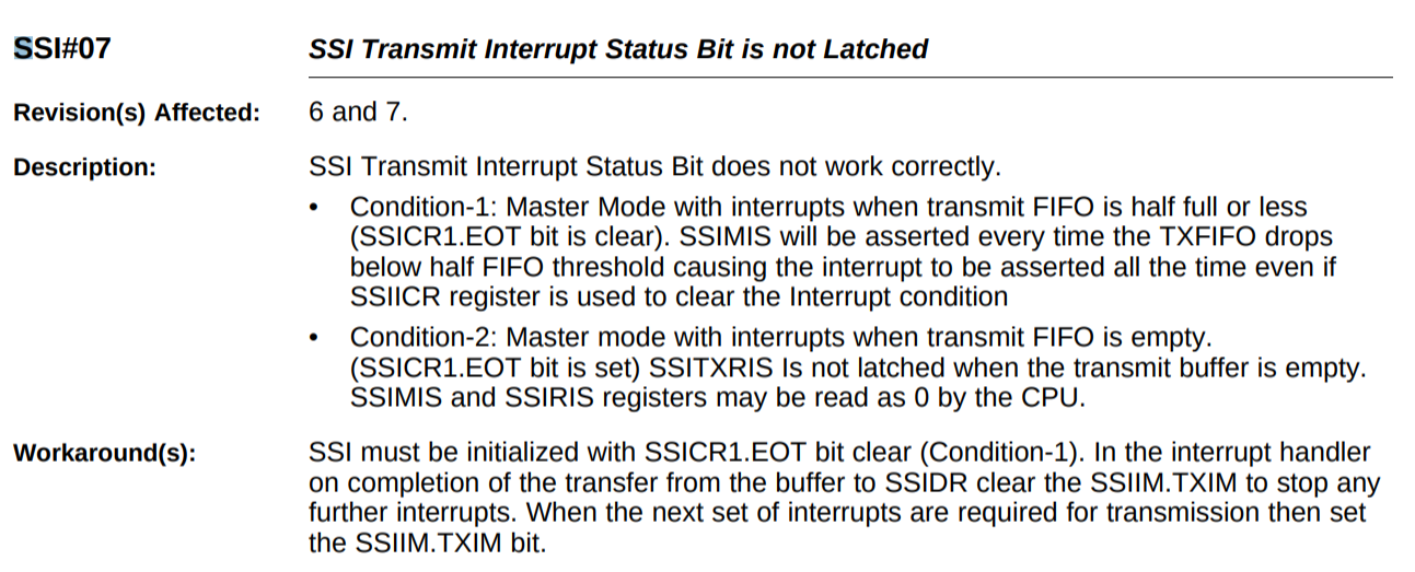
Can someone explain to me the errata SSI#07 of the TM4C123x. It's shown in document SPMZ849F (link).

I'm trying to get an interrupt when the SSI is done transmitting (SSI_TXEOT). Whatever I try, I either get no interrupt, or an infinite amount of them.

Code to setup SSI0:

void
PinoutSet(void)
{
    // Enable Peripheral Clocks.
    MAP_SysCtlPeripheralEnable(SYSCTL_PERIPH_GPIOA);

    // PA[5:2] are used for SSI0.
    MAP_GPIOPinConfigure(GPIO_PA2_SSI0CLK);
    MAP_GPIOPinConfigure(GPIO_PA3_SSI0FSS);
    MAP_GPIOPinConfigure(GPIO_PA4_SSI0RX);
    MAP_GPIOPinConfigure(GPIO_PA5_SSI0TX);
    MAP_GPIOPinTypeSSI(GPIO_PORTA_BASE, GPIO_PIN_5 | GPIO_PIN_4 | GPIO_PIN_3 |
                       GPIO_PIN_2);
}

Code to initialize SSI0:

// Enable SSI0
MAP_SysCtlPeripheralDisable(SYSCTL_PERIPH_SSI0);
MAP_SysCtlPeripheralReset(SYSCTL_PERIPH_SSI0);
MAP_SysCtlPeripheralEnable(SYSCTL_PERIPH_SSI0);
while(!MAP_SysCtlPeripheralReady(SYSCTL_PERIPH_SSI0));

// Configure SSI, 1MHz, 8-bit data, master mode.
SSIConfigSetExpClk(SSI0_BASE, SysCtlClockGet(), SSI_FRF_TI, SSI_MODE_MASTER, 1000000, 8);

// Enable the SSI0 module.
SSIEnable(SSI0_BASE);

// Enable interrupts
SSIIntDisable(SSI0_BASE, SSI_TXFF | SSI_RXFF | SSI_RXTO | SSI_RXOR);
SSIIntClear(SSI0_BASE, SSI_TXFF | SSI_RXFF | SSI_RXTO | SSI_RXOR);
HWREG(SSI0_BASE + SSI_O_CR1) |= SSI_CR1_EOT;  // TX interrupt becomes EOT interrupt
SSIIntEnable(SSI0_BASE, SSI_TXFF);
ROM_IntEnable(INT_SSI0);
ROM_IntMasterEnable();

And the interrupt handler:

void
SSI0IntHandler(void)
{
    volatile unsigned long status = 0;

    status = SSIIntStatus(SSI0_BASE, true);
    SSIIntClear(SSI0_BASE, SSI_TXFF | SSI_RXFF | SSI_RXTO | SSI_RXOR);

    // HWREG(SSI0_BASE + SSI_O_IM) &= ~SSI_IM_TXIM;
}

When I do get an infinite amount of interrupts; status is set to 8.

Any hints/tips on getting this to work? or am I misinterpreting the errata and is this impossible?

  • Hi Andrew,

    In your SSI0IntHandler() can you do a read back of the SSIMIS register after the SSIIntClear(). Basically like below code. What I suspect is a race condition where you exit the ISR immediately after you try to clear the interrupt flags. It takes some cycles to physically clear these flags but you have already exited the ISR. Before these flags are actually cleared the interrupt is still pending to the NVIC and the ISR is re-entered. Normally you would have some code to process the data such as reloading the FIFO after your clear the interrupt flags. These instructions will take more than enough cycles for the clearing of the interrupt flags to complete. Please give a try and see if it makes a difference. Hopefully this is the problem, if not we will debug further.

    status = SSIIntStatus(SSI0_BASE, true);
    SSIIntClear(SSI0_BASE, SSI_TXFF | SSI_RXFF | SSI_RXTO | SSI_RXOR);
    status = SSIIntStatus(SSI0_BASE, true);
  • Dear Charles,

    Unfortunately it is not that the time spent in the interrupt service routine is too short for the processor to clear the flag. I have extended the code and paste it below in full.

    #include <stdint.h>
    #include <stdbool.h>
    #include "inc/hw_ints.h"
    #include "inc/hw_memmap.h"
    #include "inc/hw_nvic.h"
    #include "inc/hw_types.h"
    #include "inc/hw_ssi.h"
    #include "driverlib/debug.h"
    #include "driverlib/fpu.h"
    #include "driverlib/gpio.h"
    #include "driverlib/interrupt.h"
    #include "driverlib/pin_map.h"
    #include "driverlib/rom.h"
    #include "driverlib/rom_map.h"
    #include "driverlib/ssi.h"
    #include "driverlib/sysctl.h"
    #include "driverlib/systick.h"
    #include "driverlib/uart.h"
    #include "utils/uartstdio.h"
    
    
    #ifdef DEBUG
    void
    __error__(char *pcFilename, uint32_t ui32Line)
    {
    }
    #endif
    
    
    void
    PinoutSet(void)
    {
        // Enable Peripheral Clocks.
        MAP_SysCtlPeripheralEnable(SYSCTL_PERIPH_GPIOA);
    
        // PA[1:0] are used for UART0 (ICDI).
        MAP_GPIOPinConfigure(GPIO_PA0_U0RX);
        MAP_GPIOPinConfigure(GPIO_PA1_U0TX);
        MAP_GPIOPinTypeUART(GPIO_PORTA_BASE, GPIO_PIN_0 | GPIO_PIN_1);
    
        // PA[5:2] are used for SSI0.
        MAP_GPIOPinConfigure(GPIO_PA2_SSI0CLK);
        MAP_GPIOPinConfigure(GPIO_PA3_SSI0FSS);
        MAP_GPIOPinConfigure(GPIO_PA4_SSI0RX);
        MAP_GPIOPinConfigure(GPIO_PA5_SSI0TX);
        MAP_GPIOPinTypeSSI(GPIO_PORTA_BASE, GPIO_PIN_5 | GPIO_PIN_4 | GPIO_PIN_3 |
                           GPIO_PIN_2);
    }
    
    
    void
    SSI0IntHandler(void)
    {
        uint32_t ui32Status;
    
        // Read SSIMIS (SSI Masked Interrupt Status)
        ui32Status = SSIIntStatus(SSI0_BASE, true);
        SSIIntClear(SSI0_BASE, ui32Status);
    
        // Clear SSIIM.TXIM to stop further interrupts
        HWREG(SSI0_BASE + SSI_O_IM) &= ~(SSI_IM_TXIM);
    
        // Small delay
        ROM_SysCtlDelay(10);
    
        UARTprintf("ISR: ui32Status = %x\n", ui32Status);
    }
    
    
    void
    ConsoleInit(void)
    {
        // Enable UART0
        MAP_SysCtlPeripheralDisable(SYSCTL_PERIPH_UART0);
        MAP_SysCtlPeripheralReset(SYSCTL_PERIPH_UART0);
        MAP_SysCtlPeripheralEnable(SYSCTL_PERIPH_UART0);
        while(!MAP_SysCtlPeripheralReady(SYSCTL_PERIPH_UART0));
    
        // Use the internal 16MHz oscillator as the UART clock source.
        MAP_UARTClockSourceSet(UART0_BASE, UART_CLOCK_PIOSC);
    
        // Initialize the UART for console I/O.
        UARTStdioConfig(0, 115200, 16000000);
    }
    
    
    int
    main(void)
    {
        uint32_t ui32DataRx;
    
        // Set the system clock to run from PLL at 40 MHz.
        ROM_SysCtlClockSet(SYSCTL_SYSDIV_5 | SYSCTL_USE_PLL | SYSCTL_XTAL_16MHZ |
                           SYSCTL_OSC_MAIN);
    
        // Configure the device pins.
        PinoutSet();
    
        // Enable and initialize the UART.
        ConsoleInit();
    
        // DEBUG
        UARTprintf("\n\nEnabling SSI0\n");
    
        // Enable SSI0
        MAP_SysCtlPeripheralDisable(SYSCTL_PERIPH_SSI0);
        MAP_SysCtlPeripheralReset(SYSCTL_PERIPH_SSI0);
        MAP_SysCtlPeripheralEnable(SYSCTL_PERIPH_SSI0);
        while(!MAP_SysCtlPeripheralReady(SYSCTL_PERIPH_SSI0));
    
        // Configure SSI, 1MHz, 8-bit data, master mode.
        SSIConfigSetExpClk(SSI0_BASE, SysCtlClockGet(), SSI_FRF_MOTO_MODE_0,
                           SSI_MODE_MASTER, 1000000, 8);
    
        // Enable the SSI0 module.
        SSIEnable(SSI0_BASE);    // Equiv. to:  HWREG(SSI0_BASE + SSI_O_CR1) |= SSI_CR1_SSE;
        UARTprintf("SSI0 enabled\n");
    
        // Enable SSI TX EOT interrupt
        IntEnable(INT_SSI0);
        SSIIntEnable(SSI0_BASE, SSI_TXFF);    // Equiv. to:  HWREG(SSI0_BASE + SSI_O_IM) |= SSI_TXFF;
        HWREG(SSI0_BASE + SSI_O_CR1) |= SSI_CR1_EOT;  // TXFF interrupt becomes EOT interrupt
        IntMasterEnable();
        UARTprintf("Interrupts enabled\n"); 
    
        // Read any residual data from the SSI port. 
        while(SSIDataGetNonBlocking(SSI0_BASE, &ui32DataRx));
        UARTprintf("Residual data read\n");
    
        // Set SSIIM.TXIM bit for next round
        HWREG(SSI0_BASE + SSI_O_IM) |= SSI_IM_TXIM;
        UARTprintf("SSIIM.TXIM set\n");
    
        // Write single byte to SSI FIFO
        SSIDataPut(SSI0_BASE, 0x000000ab);
        UARTprintf("FIFO loaded\n");
    
        // Busy-wait loop; expect interrupt before UARTprintf
        while(SSIBusy(SSI0_BASE));
        UARTprintf("Done writing\n");
    
        // Read one byte
        SSIDataGet(SSI0_BASE, &ui32DataRx);
        UARTprintf("SSI transaction completed\n");
    
        // Sleep 1s
        ROM_SysCtlDelay(ROM_SysCtlClockGet() / 3);
        UARTprintf("End of delay\n");
    
        // Disable interrupts to the processor; loop forever
        ROM_IntMasterDisable();
        while(1)
        {
        }
    }

    There is both a SysCtlDelay as well as a UARTprintf now in the ISR. That should be plenty of time for the processor to clear the interrupt flag.

    Output from the console is:

    Enabling SSI0
    SSI0 enabled
    ISR: ui32Status = 8
    Interrupts enabled
    Residual data read
    SSIIM.TXIM set
    ISR: ui32Status = 0
    FIFO loaded
    Done writing
    SSI transaction completed
    End of delay

    What is strange to me is that the interrupt is triggered immediately after enabling interrupts (before UARTprintf can output 'Interrupts enabled'). The first time ui32Status = 8 seems the right one (although there is no EOT here). I cleared SSIIM.TXIM inside the ISR to stop the flood of interrupts. If I set the TXIM bit again, it seems that the interrupt is now indeed triggered at EOT, but somehow ui32Status = 0... (i.e. no interrupt?).

    To be continued...

  • Hi Andrew,
    I can replicate your result and spend more time tomorrow.
  • Hi Andrew,

      Again what you have seen where the ui32Status is read zero is the result of Errata SSI#7 for condition-2. 


  • Hi Charles,

    I managed to get the EOT interrupt working. See the example code below; might be useful if someone runs into a similar problem. I still have to confirm the timing using an oscilloscope by comparing the SPI CS line (PA3) and PF3, but I do not expect issues there.

    What caught me off guard was that you first need set the EOT bit in SSICR1 before enabling the SSI_TXFF interrupt, or else it will immediately call the ISR. Easy pitfall :-). There is no need for the workaround (to clear SSIIM.TXIM) if you are working in Condition-2; you only need to be aware that SSIIntStatus will return 0. The documentation could be more clear in this.

    Thanks for your support!

    #include <stdint.h>
    #include <stdbool.h>
    #include "inc/hw_ints.h"
    #include "inc/hw_memmap.h"
    #include "inc/hw_nvic.h"
    #include "inc/hw_types.h"
    #include "inc/hw_ssi.h"
    #include "driverlib/fpu.h"
    #include "driverlib/gpio.h"
    #include "driverlib/interrupt.h"
    #include "driverlib/pin_map.h"
    #include "driverlib/rom.h"
    #include "driverlib/rom_map.h"
    #include "driverlib/ssi.h"
    #include "driverlib/sysctl.h"
    #include "driverlib/systick.h"
    #include "driverlib/uart.h"
    #include "utils/uartstdio.h"
    
    
    // The count of interrupts received.
    volatile uint32_t g_ui32IntCounter;
    
    void
    PinoutSet(void)
    {
        // Enable Peripheral Clocks.
        MAP_SysCtlPeripheralEnable(SYSCTL_PERIPH_GPIOA);
        MAP_SysCtlPeripheralEnable(SYSCTL_PERIPH_GPIOF);
    
        // PA[1:0] are used for UART0 (ICDI).
        MAP_GPIOPinConfigure(GPIO_PA0_U0RX);
        MAP_GPIOPinConfigure(GPIO_PA1_U0TX);
        MAP_GPIOPinTypeUART(GPIO_PORTA_BASE, GPIO_PIN_0 | GPIO_PIN_1);
    
        // PA[5:2] are used for SSI0.
        MAP_GPIOPinConfigure(GPIO_PA2_SSI0CLK);
        MAP_GPIOPinConfigure(GPIO_PA3_SSI0FSS);
        MAP_GPIOPinConfigure(GPIO_PA4_SSI0RX);
        MAP_GPIOPinConfigure(GPIO_PA5_SSI0TX);
        MAP_GPIOPinTypeSSI(GPIO_PORTA_BASE, GPIO_PIN_5 | GPIO_PIN_4 | GPIO_PIN_3 |
                           GPIO_PIN_2);
    
        // PF3 is used to indicate ISR exit.
        MAP_GPIOPinTypeGPIOOutput(GPIO_PORTF_BASE, GPIO_PIN_3);
    }
    
    void
    SSI0IntHandler(void)
    {
        uint32_t ui32Status;
    
        // Read SSIMIS (SSI Masked Interrupt Status)
        ui32Status = SSIIntStatus(SSI0_BASE, true);
        SSIIntClear(SSI0_BASE, ui32Status);
    
        // Increment the interrupt counter.
        g_ui32IntCounter++;
    
        // Toggle PF3 to indicate interrupt handler exit.
        ROM_GPIOPinWrite(GPIO_PORTF_BASE, GPIO_PIN_3,
                         (ROM_GPIOPinRead(GPIO_PORTF_BASE, GPIO_PIN_3) ^
                          GPIO_PIN_3));
    }
    
    void
    SPIInit(void)
    {
        // Enable SSI0
        MAP_SysCtlPeripheralDisable(SYSCTL_PERIPH_SSI0);
        MAP_SysCtlPeripheralReset(SYSCTL_PERIPH_SSI0);
        MAP_SysCtlPeripheralEnable(SYSCTL_PERIPH_SSI0);
        while(!MAP_SysCtlPeripheralReady(SYSCTL_PERIPH_SSI0));
    
        // Configure SSI, 1MHz, 8-bit data, master mode.
        SSIConfigSetExpClk(SSI0_BASE, SysCtlClockGet(), SSI_FRF_MOTO_MODE_0,
                           SSI_MODE_MASTER, 1000000, 8);
    
        // Enable the SSI0 module.
        SSIEnable(SSI0_BASE);
    
        // Enable End of Transmit interrupt mode for the TXRIS interrupt.
        HWREG(SSI0_BASE + SSI_O_CR1) |= SSI_CR1_EOT;
    
        // Enable the SSI0 interrupt.
        IntEnable(INT_SSI0);
    
        // Enable the SSI_TXEOT interrupt source.
        SSIIntEnable(SSI0_BASE, SSI_TXFF);
    }
    
    void
    SSIEOTTestCase(void)
    {
    }
    
    void
    ConsoleInit(void)
    {
        // Enable UART0
        MAP_SysCtlPeripheralDisable(SYSCTL_PERIPH_UART0);
        MAP_SysCtlPeripheralReset(SYSCTL_PERIPH_UART0);
        MAP_SysCtlPeripheralEnable(SYSCTL_PERIPH_UART0);
        while(!MAP_SysCtlPeripheralReady(SYSCTL_PERIPH_UART0));
    
        // Use the internal 16MHz oscillator as the UART clock source.
        MAP_UARTClockSourceSet(UART0_BASE, UART_CLOCK_PIOSC);
    
        // Initialize the UART for console I/O.
        UARTStdioConfig(0, 115200, 16000000);
    }


    int
    main(void)
    {
        uint32_t ui32Length;
        uint32_t ui32Index;
    
        // Set the system clock to run from PLL at 40 MHz.
        ROM_SysCtlClockSet(SYSCTL_SYSDIV_5 | SYSCTL_USE_PLL | SYSCTL_XTAL_16MHZ |
                           SYSCTL_OSC_MAIN);
    
        // Configure the device pins.
        PinoutSet();
    
        // Enable and initialize the UART.
        ConsoleInit();
    
        // Enable and initialize the SPI interface.
        SPIInit();
    
        // Enable interrupts to the processor.
        ROM_IntMasterEnable();
    
        // Write messages of varying length. Interrupt should only occur at end
        // of transmission.
        for(ui32Length = 1; ui32Length <= 10; ui32Length++)
        {
            // Reset the interrupt counter.
            g_ui32IntCounter = 0;
    
            ui32Index = ui32Length;
            while(ui32Index)
            {
                SSIDataPut(SSI0_BASE, ui32Index);
                ui32Index--;
            }
            while(SSIBusy(SSI0_BASE));  // Interrupt should occur here
    
            // Verify that the interrupt was only fired once.
            if(g_ui32IntCounter != 1)
            {
                UARTprintf("ui32Length = %d, g_ui32IntCounter = %d\n", 
                           ui32Length, g_ui32IntCounter);
            }
        }
        UARTprintf("done.\n");
    
        // Disable interrupts to the processor; loop forever
        ROM_IntMasterDisable();
        while(1)
        {
        }
    }

  • Hi Andrew,
    Glad you problem is solved and thanks for sharing the tip to first set EOT bit before enabling TXFF interrupt for condition-2 usage.