This thread has been locked.

If you have a related question, please click the "Ask a related question" button in the top right corner. The newly created question will be automatically linked to this question.

CCS/TM4C123GH6PM: TM4C123GH6PM

Part Number: TM4C123GH6PM


Tool/software: Code Composer Studio

I'm trying to wrap my brain around why the open drain has a voltage across it.  I'm using GPIO PA7.  In code composer I've got the lines:

SysCtlPeripheralEnable(SYSCTL_PERIPH_GPIOA);
GPIOPinTypeGPIOOutputOD(GPIO_PORTA_BASE, GPIO_PIN_7);

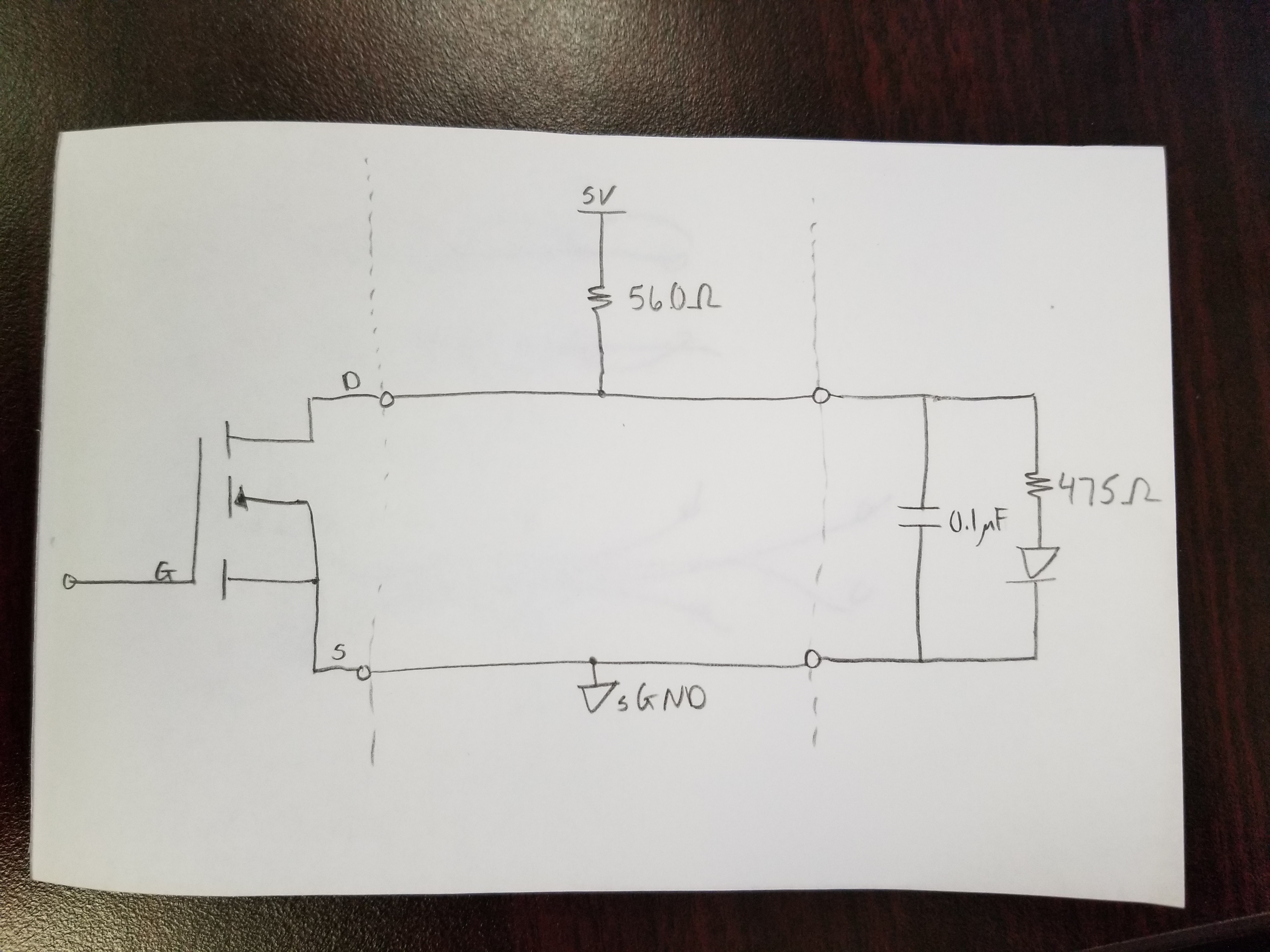
I'm trying to drive an optoisolator (see circuit in image).  When the GPIO goes high it pulls the drain to ~1.3 to 1.5 V.  Should the voltage between the D to S voltage be that much?

  • Your subject line isn't helping you.

    Now in this case

    • with the MOSFET on you have
      • 5V across ~560 Ohms drawing ~9mA --> drop across D/S of ~0
    • with the MOSFET off you have
      • 5V across ~1k plus a diode drop, with a diode drop of 1V that gives you a current of ~3.8mA. and a drop across the 560R resistor of ~2V1 --> drop across D/S of ~2V9

    Now if the forward diode drop is a lot less (you aren't driving very much current through that diode) then seeing that drop wouldn't be surprising.

    1V3 still seems low but if you've any other parasitics or that cap has any significant leakage then lower voltages are certainly possible. Especially check the characteristics of the GPIO in OD mode, given that this is a multi-function pin it's likely not as clean as you've drawn.

    This also seems an odd way to drive an opto. You draw more current when the opto is off than you do through the opto when it is on and your current even when on seems low.

    Robert

    Side note: I would use the GPIO to directly drive the current as you do, I'd move that to a discrete MOSFET to reduce the stain on the micro and get higher driving currents and voltages in the bargain.

  • Robert Adsett72 said:
    Your subject line isn't helping you.

    So well said - yet (another) "feature" of the forum's (pardon) "claimed upgrade."

    Also - your "Tags" - so vastly superior to those "uninspired, boiler-plate, advertising vehicles" - forced down our throats by those, "all knowing."

    Clearly - attempting to employ the MCU directly - rather than imposing a low cost FET - makes little sense.    Such a "FET Controlled" design accepts drive from (any) MCU - or a simple gate - thus may be "re-used" - always a highly valued, "Time & Effort Saver!"

    I'm wrapping my head around the "motivation" to "save the cost" of a 0.20 (USD) FET... (especially even after the attempt proves, "not to par.")

  • cb1_mobile said:
    I'm wrapping my head around the "motivation" to "save the cost" of a 0.20 (USD) FET

    2N7002 - Vgsth = 2V4 max, Multi-sourced, 0.02ea in reel quantities. 0.08 ea/C @Digikey

    BSS123  - Vgsth - 2V max, Multi-sourced, 0.04ea in reel quantities. 0.10 ea/C @Digikey

    The BSS123 gives you a higher voltage for that price. They're really only typically qualified for gate voltages below 5V (they do provide the typical curves though) but unless you are at the limits you likely have room given the threshold voltages. Need to check when designing.

    Robert