Part Number: TM4C1294NCPDT
Tool/software: Code Composer Studio
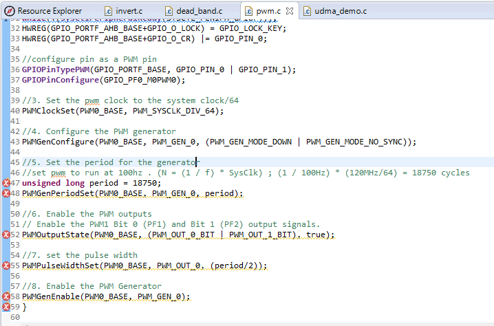
This is the driver for PWM. I have found the error as below.
#include <stdbool.h>
#include <stdint.h>
#include "inc/hw_types.h"
#include "inc/hw_gpio.h"
#include "inc/hw_memmap.h"
#include "driverlib/gpio.h"
#include "driverlib/pin_map.h"
#include "driverlib/pwm.h"
#include "driverlib/sysctl.h"
#include "driverlib/uart.h"
#include "utils/uartstdio.h"
#include "drivers/pinout.h"
#include "driverlib/rom_map.h"
//system clock variable
uint32_t g_ui32SysClock;
int main(void){
//1. set the clock to run off of crystal at 25Mhz
g_ui32SysClock = MAP_SysCtlClockFreqSet((SYSCTL_XTAL_25MHZ | SYSCTL_OSC_MAIN \
| SYSCTL_USE_PLL | SYSCTL_CFG_VCO_480), 120000000);
//2. Enable the PWM Module in the System Control using
//enable peripheral (port F)
SysCtlPeripheralEnable(SYSCTL_PERIPH_PWM0);
SysCtlPeripheralEnable(SYSCTL_PERIPH_GPIOF);
//2b. secret level; unlock port F0 so that we can use it!!! >=O
while(!(SysCtlPeripheralReady(SYSCTL_PERIPH_GPIOF)));
HWREG(GPIO_PORTF_AHB_BASE+GPIO_O_LOCK) = GPIO_LOCK_KEY;
HWREG(GPIO_PORTF_AHB_BASE+GPIO_O_CR) |= GPIO_PIN_0;
//configure pin as a PWM pin
GPIOPinTypePWM(GPIO_PORTF_BASE, GPIO_PIN_0 | GPIO_PIN_1);
GPIOPinConfigure(GPIO_PF0_M0PWM0);
//3. Set the pwm clock to the system clock/64
PWMClockSet(PWM0_BASE, PWM_SYSCLK_DIV_64);
//4. Configure the PWM generator
PWMGenConfigure(PWM0_BASE, PWM_GEN_0, (PWM_GEN_MODE_DOWN | PWM_GEN_MODE_NO_SYNC));
//5. Set the period for the generator
//set pwm to run at 100hz . (N = (1 / f) * SysClk) ; (1 / 100Hz) * (120MHz/64) = 18750 cycles
unsigned long period = 18750;
PWMGenPeriodSet(PWM0_BASE, PWM_GEN_0, period);
//6. Enable the PWM outputs
// Enable the PWM1 Bit 0 (PF1) and Bit 1 (PF2) output signals.
PWMOutputState(PWM0_BASE, (PWM_OUT_0_BIT | PWM_OUT_1_BIT), true);
//7. set the pulse width
PWMPulseWidthSet(PWM0_BASE, PWM_OUT_0, (period/2));
//8. Enable the PWM Generator
PWMGenEnable(PWM0_BASE, PWM_GEN_0);
}
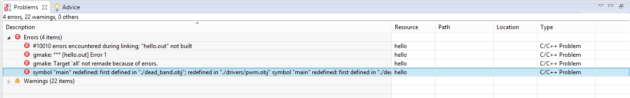
The errors are
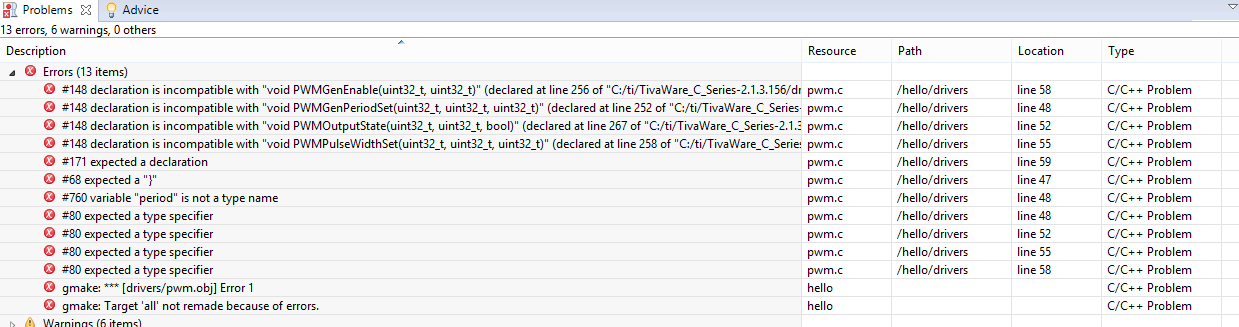
The errors are marked in this area of the program as shown below.