This thread has been locked.

If you have a related question, please click the "Ask a related question" button in the top right corner. The newly created question will be automatically linked to this question.

CCS/TM4C123GH6PM: unable to display message on LCD 16x2.

Part Number: TM4C123GH6PM


Tool/software: Code Composer Studio

Hi 

I am using JHD 162A LCD module to display a message("Hello world").

I am able to build code without errors but when I tried to run it, the program stucked into exit.c file.

And the LCD is displaying:

1st row - 16 "5X7" matrix

2nd row - blank.

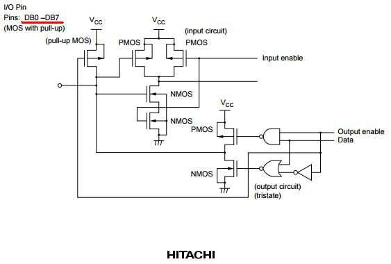
// PB0-7 -> Data lines D0-D7
// PD0 -> RS
// PD1 -> Enable

//**********************************************************************88

#include <stdint.h>
#include <stdbool.h>
#include "inc/hw_memmap.h"
#include "inc/hw_types.h"
#include "driverlib/sysctl.h"
#include "driverlib/gpio.h"

unsigned char pins=(GPIO_PIN_0 | GPIO_PIN_1 | GPIO_PIN_2 | GPIO_PIN_3 | GPIO_PIN_4 | GPIO_PIN_5 | GPIO_PIN_6 | GPIO_PIN_7);

void Lcd_data(unsigned char data)
{
    GPIOPinWrite(GPIO_PORTB_BASE, pins, data); //Put on the Data Pins 0x01 to Clear LCD screen
    GPIOPinWrite(GPIO_PORTD_BASE, GPIO_PIN_0|GPIO_PIN_1,0x03); //RS=1 | E=1
    SysCtlDelay(2); //Enable Pulse Width (High Level) 230 nano second
    GPIOPinWrite(GPIO_PORTD_BASE, GPIO_PIN_0|GPIO_PIN_1,0x01); //RS=1 | E=0

    SysCtlDelay(4167); //1 milliseconds delay
}


void Display(unsigned char *str)
{
    while(*str)
    {
        Lcd_data(*str);
        str++;
    }
}


int main(void)
{

    SysCtlClockSet(SYSCTL_SYSDIV_16|SYSCTL_USE_PLL|SYSCTL_XTAL_16MHZ|SYSCTL_OSC_MAIN); //12.5MHz

    SysCtlPeripheralEnable(SYSCTL_PERIPH_GPIOD);
    SysCtlPeripheralEnable(SYSCTL_PERIPH_GPIOB);

    GPIOPinTypeGPIOOutput(GPIO_PORTB_BASE, GPIO_PIN_0|GPIO_PIN_1|GPIO_PIN_2|GPIO_PIN_3| GPIO_PIN_4| GPIO_PIN_5| GPIO_PIN_6| GPIO_PIN_7);
    GPIOPinTypeGPIOOutput(GPIO_PORTD_BASE, GPIO_PIN_0|GPIO_PIN_1);

    //Wait 15 Miliseconds after LCD Power Up//
    SysCtlDelay(62500);

    GPIOPinWrite(GPIO_PORTD_BASE, GPIO_PIN_0|GPIO_PIN_1,0x00); //RS=0 | E=0


    //Initialize the LCD display with commands

    GPIOPinWrite(GPIO_PORTB_BASE, pins, 0x38); //Put on the Data Pins 0x38 to get 2 Lines 5x7 Matrix
    GPIOPinWrite(GPIO_PORTD_BASE, GPIO_PIN_0|GPIO_PIN_1,0x02); //RS=0 | E=1
    SysCtlDelay(2); //Enable Pulse Width (High Level) 230 nano second
    GPIOPinWrite(GPIO_PORTD_BASE, GPIO_PIN_0|GPIO_PIN_1,0x00); //RS=0 | E=0

    SysCtlDelay(4167); //1 milliseconds delay

    GPIOPinWrite(GPIO_PORTB_BASE, pins, 0x0c); //Put on the Data Pins 0x0c to Display ON cursor OFF
    GPIOPinWrite(GPIO_PORTD_BASE, GPIO_PIN_0|GPIO_PIN_1,0x02); //RS=0 | E=1
    SysCtlDelay(2); //Enable Pulse Width (High Level) 230 nano second
    GPIOPinWrite(GPIO_PORTD_BASE, GPIO_PIN_0|GPIO_PIN_1,0x00); //RS=0 | E=0

    SysCtlDelay(4167); //1 milliseconds delay

    GPIOPinWrite(GPIO_PORTB_BASE, pins, 0x0e); //Put on the Data Pins 0x0e to Display ON cursor ON
    GPIOPinWrite(GPIO_PORTD_BASE, GPIO_PIN_0|GPIO_PIN_1,0x02); //RS=0 | E=1
    SysCtlDelay(2); //Enable Pulse Width (High Level) 230 nano second
    GPIOPinWrite(GPIO_PORTD_BASE, GPIO_PIN_0|GPIO_PIN_1,0x00); //RS=0 | E=0

    SysCtlDelay(4167); //1 milliseconds delay

    GPIOPinWrite(GPIO_PORTB_BASE, pins, 0x01); //Put on the Data Pins 0x01 to Clear LCD screen
    GPIOPinWrite(GPIO_PORTD_BASE, GPIO_PIN_0|GPIO_PIN_1,0x02); //RS=0 | E=1
    SysCtlDelay(2); //Enable Pulse Width (High Level) 230 nano second
    GPIOPinWrite(GPIO_PORTD_BASE, GPIO_PIN_0|GPIO_PIN_1,0x00); //RS=0 | E=0

    SysCtlDelay(4167); //1 milliseconds delay

    GPIOPinWrite(GPIO_PORTD_BASE, GPIO_PIN_0|GPIO_PIN_1,0x01); //RS=1 | E=0

    Display("Hello world");


}

I have compiled this code from various posts from this community.

  • Is your "issue's description" as clear & direct as you desire?      Note your (important) Subject Line, "Unable to display message on LCD 16x2."

    Yet - very shortly thereafter - you note that the "top Lcd row" displays, "16 "5x7" matrix."     Thus your subject line is in dire conflict w/your reported results - is it not?

    The fact that you have achieved, "even a single row of Lcd success" likely notes that (much) of your vital, "Lcd initialization code" proves correct.    (Good that!)

    Now - "failure to achieve display on the 2nd row of a 2x16 Lcd module usually results from:

    • initializing the Lcd as a "single row" device
    • failing to direct the Lcd's cursor to the left-edge of row 2 (achieved via sending the address 0xC0 - prior to any writes to row 2)

    Note that such "Lcd addressing" is considered a "Command" - thus must be done w/control line, "RS"=0.    Data writes which then follow - require "RS"=1.

    Looking (very briefly) at your "borrowed from various posts code" - I note that your Lcd initialization code is improper!      The "0x38" value is correct (for 2 row display) - but must be repeated - and (other) vital parts of the initialization sequence - appear to be missing.

    Your use of this forum's "Search Box" (atop this page) should find the "Master (defining) Lcd specification (HD44780)" which I contributed/placed here - long ago.    (your search "keywords" Lcd and cb1/cb1_mobile should locate.     (or you can search the net for HD44780 - and follow the 8 bit initialization sequence - specified.

    I did not make the time/effort to discover if you've (properly) "Steered the Lcd's cursor to "Row 2" - I HAVE provided sufficient detail for your review (and execution) of that process.

  • Here is how I initialized it again

    GPIOPinWrite(GPIO_PORTD_BASE, GPIO_PIN_0|GPIO_PIN_1,0x00); //RS=0 | E=0


        //Initialize the LCD display with commands
    
        GPIOPinWrite(GPIO_PORTB_BASE, pins, 0x38); //Put on the Data Pins 0x38 to get 2 Lines 5x7 Matrix
        GPIOPinWrite(GPIO_PORTD_BASE, GPIO_PIN_0|GPIO_PIN_1,0x02); //RS=0 | E=1
        SysCtlDelay(4167); //Enable Pulse Width (High Level) 1 milli second
        GPIOPinWrite(GPIO_PORTD_BASE, GPIO_PIN_0|GPIO_PIN_1,0x00); //RS=0 | E=0
    
        SysCtlDelay(4167000); //1 seconds delay
    
        GPIOPinWrite(GPIO_PORTB_BASE, pins, 0x80); //Put on the Data Pins 0x0c to focus Row 1 beginning
        GPIOPinWrite(GPIO_PORTD_BASE, GPIO_PIN_0|GPIO_PIN_1,0x02); //RS=0 | E=1
        SysCtlDelay(4167); //Enable Pulse Width (High Level) 1 milli second
        GPIOPinWrite(GPIO_PORTD_BASE, GPIO_PIN_0|GPIO_PIN_1,0x00); //RS=0 | E=0
    
        SysCtlDelay(4167000); //1 seconds delay
    
        GPIOPinWrite(GPIO_PORTB_BASE, pins, 0x0e); //Put on the Data Pins 0x0e to Display ON cursor ON
        GPIOPinWrite(GPIO_PORTD_BASE, GPIO_PIN_0|GPIO_PIN_1,0x02); //RS=0 | E=1
        SysCtlDelay(4167); //Enable Pulse Width (High Level) 1 milli second
        GPIOPinWrite(GPIO_PORTD_BASE, GPIO_PIN_0|GPIO_PIN_1,0x00); //RS=0 | E=0
    
        SysCtlDelay(4167000); //1 seconds delay
    
        GPIOPinWrite(GPIO_PORTB_BASE, pins, 0x01); //Put on the Data Pins 0x01 to Clear LCD screen
        GPIOPinWrite(GPIO_PORTD_BASE, GPIO_PIN_0|GPIO_PIN_1,0x02); //RS=0 | E=1
        SysCtlDelay(4167); //Enable Pulse Width (High Level) 1 milli second
        GPIOPinWrite(GPIO_PORTD_BASE, GPIO_PIN_0|GPIO_PIN_1,0x00); //RS=0 | E=0
    
        SysCtlDelay(4167000); //1 seconds delay

    Can You suggest a sequence if I am doing it wrong

    PS:- the LCD module I am using is JHD162A (5v power is given through external source)

  • Hi , Just adding to my last comment, this is what I am getting at my LCD upon running the above given sequence

  • Pardon - but myself (likely others) note the conflict between your (just added) "photo of a blank screen" and your earlier writing:

    Himanshu Goswami said:

    And the LCD is displaying:  1st row - 16 "5X7" matrix  

    Both statements cannot be true - can they?    (very hard to "fix" - that which is NOT (properly) described.)    As this may be a "language issue" - I will do my best to assist/resolve...

    You ask that I, "Suggest a proper Lcd Initialization Sequence" - yet did I not provide you the "direction & tools" - to discover that info - yourself?      My role (if any) here is to provide "general solutions" - never "cookbooks!"    

    A "re-read" of my detailed "answering post" should guide you to such sequence!

  • cb1_mobile said:

    LCD is displaying:  1st row - 16 "5X7" matrix  

    I understand the fact "Spoonfeeding" is not a good way to learn for sure, I appreciate your detailed answer.

    but must be repeated - and (other) vital parts of the initialization sequence - appear to be missing.

    Can you point out -"What"? I couldn't find the missing part...

    I checked various forums for this Issue one of which is this 

    It shows that 0x38 command is not required twice. Is it? 

    Although I tried implementing your suggestion for 0X38 twice but got the same result. As shown in picture in the earlier post

    I tried adopting the sequence as in the mentioned link. But again, NADA, ---failed.

    At this point I am stuck so bad that I cannot think of a reason for the code to fail. (I have given enough delays to process the commands - actually more than needed)


    Quick question : JHD162A needs 5V power which I am giving through another board (C2000 microcontroller) I have shorted both the boards GNDs. I am connecting the Data pins of LCD and R/W,RS & E pins to the TM4c uC. Should this setup work? I think it should...Kindly comment!

  • Is this the LCD you are using?
    www.sunrom.com/.../526000
    If so, you may have a problem with voltage levels with Vdd at 5V. The minimum level for an input high is 0.7Vdd, which would be 3.5V. The TM4C123 has 3.3V I/O pins which may not be sufficient.
  • May I - always respectfully - disagree?      As you know - the controlling (legal) authority is the Control chip's specification sheet - and I present the KEY Page from that spec - right here - right now:

    Note further - in a past life - I've designed/produced and sold over 1M (yes million) such displays.    (perhaps difficult to "argue" w/such success...)

    And - any "Forum Search" will reveal my assist of beyond TEN such posters - guiding them to success - w/3V3 limited MCU outputs - to (most always) 5V Lcds.

    Of "special note" is the construction of the Lcd's data bus - which explains the "How & Why" of 3V3 input levels - being accepted!    Here - again from the "controlling technical source:"

    Should (further proof) be required - I offer the following: (this is a photo of a 5V Char Lcd (44780 controlled) driven by LX4F231 (w/3V3 max Vout) - proving "acceptance" of such 3V3 voltage level.

  • And - in response to poster's inability to find the Lcd's (proper) initialization coding - arrives the following:   (previously posted here by this reporter...)

    Note that as a (past) volume supplier of a most popular component (char Lcd) it is vital to, "Play it SAFE" - the following code is guaranteed to work - others (lesser) - not so much!    (thus NOT how one succeeds - in life or business...)      Those following the earlier postings - this thread - will (now) SEE the necessity for the "repeated 0x38" (for 2 row Lcd) - and that which follows:

    And - when such initialization is executed - the following results!    Again - 5V supply - LX4F231 MCU - 3V3 max output to Lcd.    Note these are "Extreme Contrast, WIDE Viewing Angle Displays.   BEST!