Part Number: TM4C129ENCPDT
Tool/software: Code Composer Studio
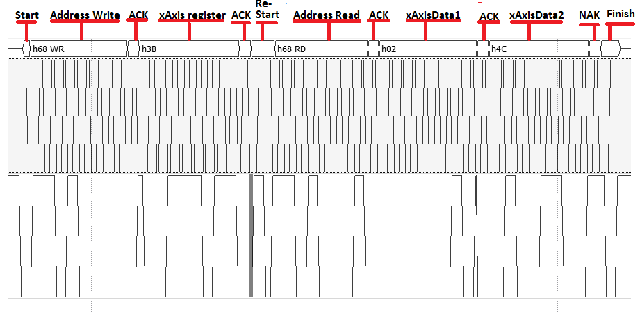
Hi, I have been working with the MPU6050, following the Arduino configuration I was able to set the 0x6B register, also it looks that the MPU6050 is sending me the ACKs, but I have a problem acquiring the data from the x-axis accelometer, whose registers are 0x3B and 0x3C. The output (pui32DataRx) is always 0, I do not know where is the error. Here is the code, someone has configure the TM4c129 to work with the MPU6050 using I2C???
#include <stdbool.h>
#include <stdint.h>
#include "inc/hw_i2c.h"
#include "inc/hw_memmap.h"
#include "inc/hw_types.h"
#include "driverlib/gpio.h"
#include "driverlib/i2c.h"
#include "driverlib/pin_map.h"
#include "driverlib/sysctl.h"
#include "driverlib/uart.h"
#include "utils/uartstdio.h"

//*****************************************************************************
//
// Number of I2C data packets to send.
//
//*****************************************************************************
#define NUM_I2C_DATA 3
#define SLAVE_ADDRESS 0x68

uint32_t ui32SysClock;
uint32_t pui32DataTx[NUM_I2C_DATA];
uint32_t pui32DataRx[2];
uint32_t ejeX;
int end = 0;

//*****************************************************************************
//
// Configure the I2C0 master and slave and connect them using loopback mode.
//
//*****************************************************************************
int
main(void)
{

    uint32_t ui32Index;

    ui32SysClock = SysCtlClockFreqSet((SYSCTL_XTAL_25MHZ |
                                           SYSCTL_OSC_MAIN |
                                           SYSCTL_USE_PLL |
                                           SYSCTL_CFG_VCO_480), 120000000);

    // The I2C0 peripheral must be enabled before use.

    SysCtlPeripheralEnable(SYSCTL_PERIPH_I2C0);
    SysCtlPeripheralEnable(SYSCTL_PERIPH_GPIOB);

    GPIOPinConfigure(GPIO_PB2_I2C0SCL);
    GPIOPinConfigure(GPIO_PB3_I2C0SDA);

    GPIOPinTypeI2CSCL(GPIO_PORTB_BASE, GPIO_PIN_2);
    GPIOPinTypeI2C(GPIO_PORTB_BASE, GPIO_PIN_3);

//  I2CLoopbackEnable(I2C0_BASE);
    I2CMasterInitExpClk(I2C0_BASE, ui32SysClock, false);
    I2CSlaveEnable(I2C0_BASE);      // Lo puedo quitar
    I2CSlaveInit(I2C0_BASE, SLAVE_ADDRESS);     //Setea la dirección del esclavo
    I2CMasterSlaveAddrSet(I2C0_BASE, SLAVE_ADDRESS, false);     // false para escribir al esclavo, true para leer al esclavo

    // Initalize the data to send.
    pui32DataTx[0] = 0x6B;
    pui32DataTx[1] = 0x00;

    for(ui32Index = 0; ui32Index < 2; ui32Index++)
    {

        I2CMasterDataPut(I2C0_BASE, pui32DataTx[ui32Index]);      // Place the data to be sent in the data register
        I2CMasterControl(I2C0_BASE, I2C_MASTER_CMD_SINGLE_SEND);

        while(!(I2CSlaveStatus(I2C0_BASE) & I2C_SLAVE_ACT_RREQ)) // Espera ACK del esclavo del reconosimiento de datos
        {
        }

        pui32DataRx[ui32Index] = I2CSlaveDataGet(I2C0_BASE); // Lee la data del esclavo

        while(I2CMasterBusy(I2C0_BASE)) //Espera a que el modulo maestro termine con la transferencia
        {
        }

        end++;
    }

    I2CMasterSlaveAddrSet(I2C0_BASE, SLAVE_ADDRESS, true);     // false para escribir al esclavo, true para leer al esclavo

    while (1)
    {
        I2CMasterDataPut(I2C0_BASE, 0x3B);      // Place the data to be sent in the data register
        I2CMasterControl(I2C0_BASE, I2C_MASTER_CMD_SINGLE_RECEIVE);

        while(!(I2CSlaveStatus(I2C0_BASE) & I2C_SLAVE_ACT_TREQ)) // Espera ACK del esclavo del reconosimiento de datos
        {
        }

        pui32DataRx[0] = I2CMasterDataGet(I2C0_BASE)<<8;

        I2CMasterDataPut(I2C0_BASE, 0x3C);      // Place the data to be sent in the data register
        I2CMasterControl(I2C0_BASE, I2C_MASTER_CMD_SINGLE_RECEIVE);

        while(!(I2CSlaveStatus(I2C0_BASE) & I2C_SLAVE_ACT_TREQ)) // Espera ACK del esclavo del reconosimiento de datos
        {
        }

        pui32DataRx[1] = I2CMasterDataGet(I2C0_BASE);
        ejeX = pui32DataRx[0]|pui32DataRx[1];
    }

//    return(0);
}