Part Number: TM4C123GH6PM
Other Parts Discussed in Thread: INA219, REF3233
Hello,
I designed a custom board for the TM4C123GH6PM microcontroller. Before doing so, I have carefully browsed this forum, and read the "System Design Guidelines for the TM4C123x Family of
TivaTM C Series Microcontrollers" and the "Using TM4C12x Devices Over JTAG Interface" documents. Before I start the PCB routing, I wanted to the circuit designed to the forum for comments and review.
This design as the usb connector and we also added a jtag header and connected it to the TM4C123 as shown in the "Using TM4C12x Devices Over JTAG Interface" document. There is also an ideal diode that prevents 5V going to computer side in case external power is used.
Here are some questions I have:
1. Wake is pulled up, or connected to ground? We currently have HIB unconnected and wake is pulled up, and vbat is connected to 3v3
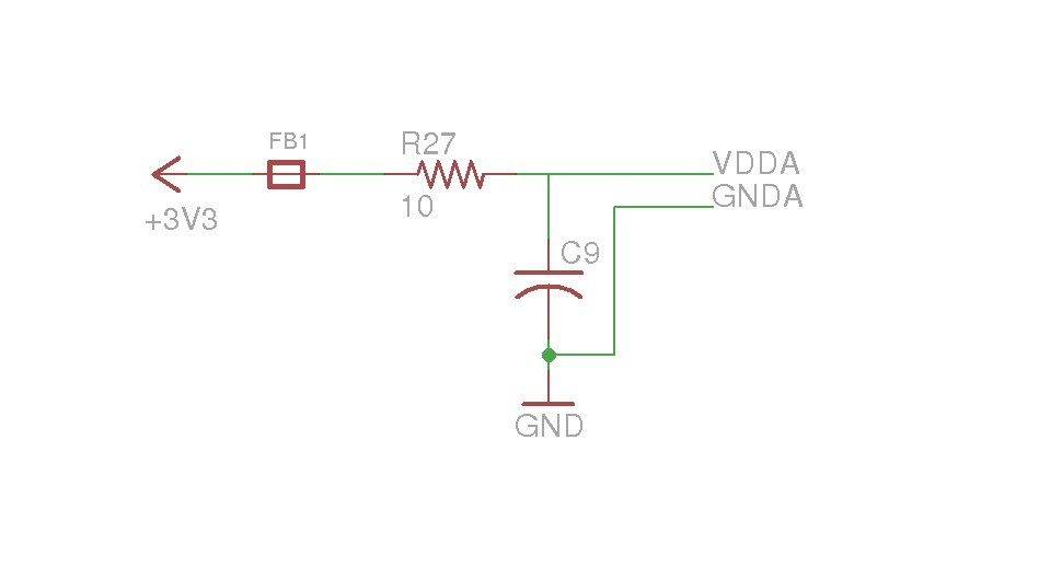
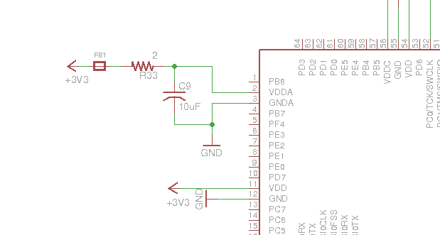
2. Is the gndx connected properly. Some designs connect it to ground.
3. we use PB0/PB1 for usb id and voltage detection. the same pins are also rx1/tx1. This means we can not use those pins as serial?
4. is the RST from the JTAG connector connected correctly? I have the same reset button design as in launchpad, but with the 220 ohm resistor, and jtag reset is connected to IC's reset
Also I am looking for a switching regulator that will take 2S or 3S li-po battery and convert it to 5V@2A-4A - as well as deploy the "Figure 7-2. Using a Crystal as the Hibernation Clock Source with a Single Battery Source" in the TM4C123GH6PM manual with an external battery, and wake button, but maybe thats for another design.
Any ideas/help/recommendations are greatly appreciated.
Best regards,
-Can