This thread has been locked.

If you have a related question, please click the "Ask a related question" button in the top right corner. The newly created question will be automatically linked to this question.

EK-TM4C129EXL: CAN Bus Transmit,Tx is Not Working

Part Number: EK-TM4C129EXL
Other Parts Discussed in Thread: EK-TM4C1294XL, TPS2052, TPS2052B

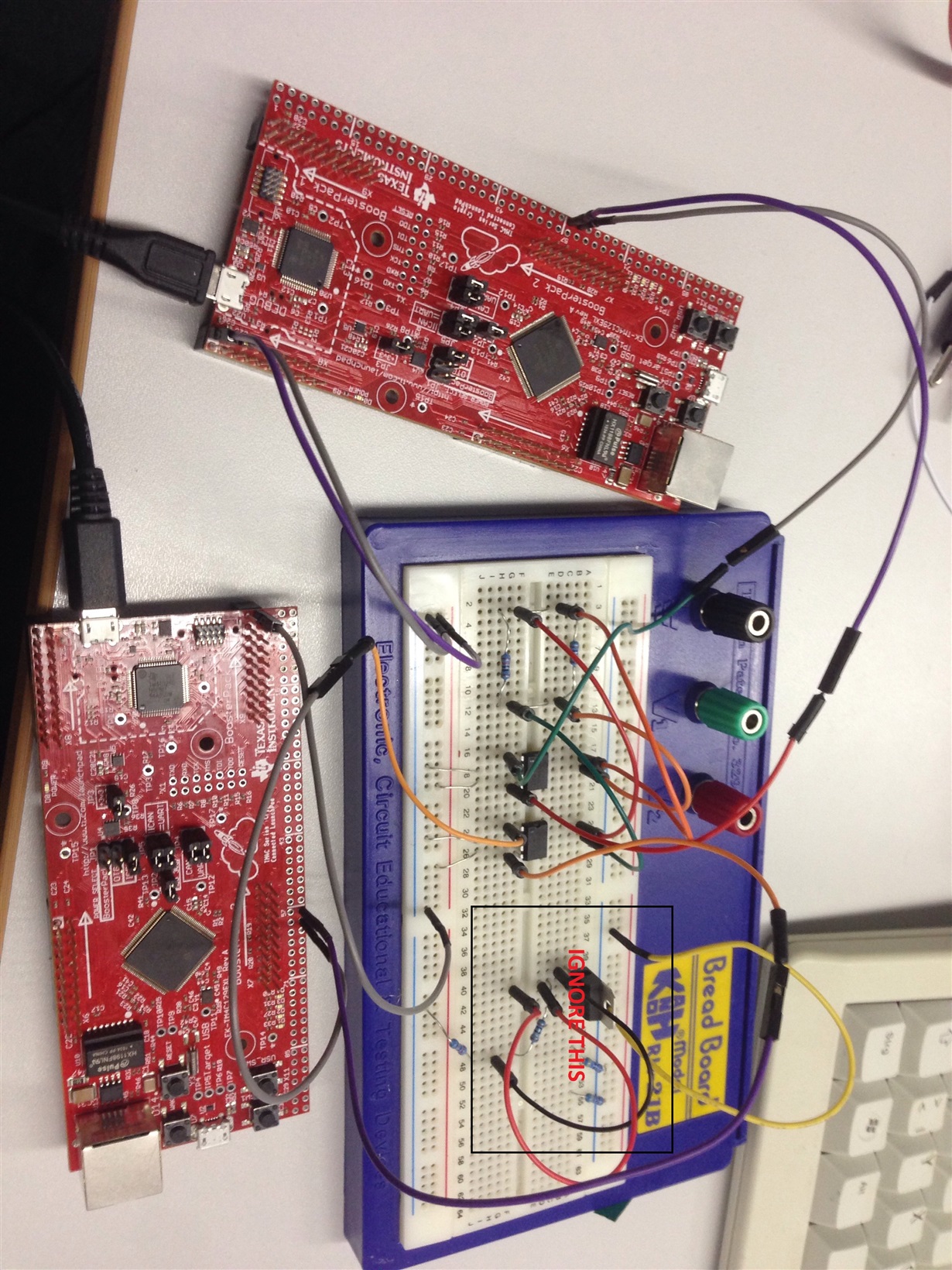
Hi All. I am very new to CAN Bus protocol and TM4C. I am given a task to transmit CAN messages from 1 TM4C129EXL to another TM4C129EXL launchpad. Since I am new to this and I need to start from somewhere, I have decided to adapt the code and the hardware from the link below : http://ohm.ninja/tiva-c-series-can-bus-with-mcp2551/  and also by refering to the sample code from C:\ti\TivaWare_C_Series-2.1.4.178\examples\peripherals\can.

I have added severel UARTprintf to the void CANIntHandler(void) to help my debugging. I have also used the oscilloscope to check CANH,CANL and TX but there are no output (hence, scope caps are not attached in this post). The JP4 and JP5 jumpers are in default configuration since CAN1 is used instead of CAN0. Please do assist.

Attached is my code for Master:

#include <stdbool.h>
#include <stdint.h>
#include <math.h>

#include "inc/hw_memmap.h"
#include "inc/hw_types.h"
#include "inc/hw_can.h"
#include "inc/hw_ints.h"
#include "driverlib/can.h"
#include "driverlib/interrupt.h"
#include "driverlib/sysctl.h"
#include "driverlib/gpio.h"
#include "driverlib/uart.h"
#include "driverlib/pin_map.h"

#include "utils/uartstdio.h"

#define PI 3.14159265359f

volatile bool errFlag = 0; // transmission error flag
unsigned int sysClock; // clockspeed in hz

void delay(unsigned int milliseconds) {
	SysCtlDelay((sysClock / 3) * (milliseconds / 1000.0f));
}

// CAN interrupt handler
void CANIntHandler(void) {

	unsigned long status = CANIntStatus(CAN1_BASE, CAN_INT_STS_CAUSE); // read interrupt status
	UARTprintf("Triggered\n");
	if(status == CAN_INT_INTID_STATUS) { // controller status interrupt
		status = CANStatusGet(CAN1_BASE, CAN_STS_CONTROL); // read back error bits, do something with them?
		errFlag = 1;
		UARTprintf("Triggered1\n");
	} else if(status == 1) { // message object 1
		CANIntClear(CAN1_BASE, 1); // clear interrupt
		errFlag = 0; // clear any error flags
		UARTprintf("Triggered2\n");
	} else { // should never happen
		UARTprintf("Unexpected CAN bus interrupt\n");
		UARTprintf("Error is-- %lu\n",status);
	}
}

int main(void) {

	tCANMsgObject msg; // the CAN message object
	unsigned int msgData; // the message data is four bytes long which we can allocate as an int32
	unsigned char *msgDataPtr = (unsigned char *)&msgData; // make a pointer to msgData so we can access individual bytes

	// Run from the PLL at 120 MHz.
	sysClock = SysCtlClockFreqSet((SYSCTL_XTAL_25MHZ | SYSCTL_OSC_MAIN | SYSCTL_USE_PLL | SYSCTL_CFG_VCO_480), 120000000);

	// Set up debugging UART
	SysCtlPeripheralEnable(SYSCTL_PERIPH_GPIOA); // enable UART0 GPIO peripheral
	SysCtlPeripheralEnable(SYSCTL_PERIPH_UART0);
	GPIOPinConfigure(GPIO_PA0_U0RX);
	GPIOPinConfigure(GPIO_PA1_U0TX);
	GPIOPinTypeUART(GPIO_PORTA_BASE, GPIO_PIN_0 | GPIO_PIN_1);
	UARTStdioConfig(0, 115200, sysClock); // 115200 baud

	// Set up CAN1
	SysCtlPeripheralEnable(SYSCTL_PERIPH_GPIOB); // enable CAN1 GPIO peripheral
	GPIOPinConfigure(GPIO_PB0_CAN1RX);
	GPIOPinConfigure(GPIO_PB1_CAN1TX);
	GPIOPinTypeCAN(GPIO_PORTB_BASE, GPIO_PIN_0 | GPIO_PIN_1);
	SysCtlPeripheralEnable(SYSCTL_PERIPH_CAN1);
	CANInit(CAN1_BASE);
	CANBitRateSet(CAN1_BASE, sysClock, 500000);
	CANIntRegister(CAN1_BASE, CANIntHandler); // use dynamic vector table allocation
	CANIntEnable(CAN1_BASE, CAN_INT_MASTER | CAN_INT_ERROR | CAN_INT_STATUS);
	IntEnable(INT_CAN1);
	CANEnable(CAN1_BASE);

	// Set up msg object
	msgData = 0;
	msg.ui32MsgID = 1;
	msg.ui32MsgIDMask = 0;
	msg.ui32Flags = MSG_OBJ_TX_INT_ENABLE;
	msg.ui32MsgLen = sizeof(msgDataPtr);
	msg.pui8MsgData = msgDataPtr;

	unsigned int t = 0; // loop counter
	float freq = 0.3; // frequency scaler

	while(1) {

		// set up next colour (scale sinf (0-1) to 0-255)
		msgDataPtr[0] = (0.5 + 0.5*sinf(t*freq)) * 0xFF;
		msgDataPtr[1] = (0.5 + 0.5*sinf(t*freq + (2*PI/3))) * 0xFF; // 120 degrees out of phase
		msgDataPtr[2] = (0.5 + 0.5*sinf(t*freq + (4*PI/3))) * 0xFF; // 240 degrees out of phase
		msgDataPtr[3] = 128; // 50% intensity

		UARTprintf("Sending colour\tr: %d\tg: %d\tb: %d\n", msgDataPtr[0], msgDataPtr[1], msgDataPtr[2]); // write colour to UART for debugging
		CANMessageSet(CAN1_BASE, 1, &msg, MSG_OBJ_TYPE_TX); // send as msg object 1

		delay(100); // wait 100ms

		if(errFlag) { // check for errors
			UARTprintf("CAN Bus Error\n");
		}

		t++; // overflow is fine
	}

	return 0;
}

Attached is my circuit diagram:

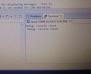
Attached is the output from the terminal:

  • Gowtham said:
    No terminal output at this moment. Due to limited resources, I am working on a method of using a RS232 cable for the UART(terminal

    Hi Gowtham,

    According to schematic notes CAN0 JP4/5 (||) only need change UART0 to UART2 in software configuration and ICDI will send printf() data as before via USB virtual COM port on your PC.

    So the scope shows 3v on TXD seems better than 5v, Curious did you have PD6 configured in software for input WPD to keep U4 EN2 disabled (Target_VBUS), turned off on TP4?  I have PD6 as (output) WPD and it works yet found it odd unless configured for digital input unless inputs can be configured as open drain, which doesn't seem plausible. Wonder if they meant PD6 is output and typed input by mistake.

    Charles might have some ideas on PD6 pin direction and seem to think only an output direction can be configured Open Drain. Seem to recall issue OTG port USB device mode PD6 configured input direction. Later  made PD6 an GPIO output and ensured USB0PEN(PD6) was not being configured in device mode.

  • BTW you marked this forum thread several posts above as being resolved, was that by mistake. If mistake you can remove the answered button.
  • BP101 said:
    If mistake you can remove the answered button.

    My, "Not quite - CAN restoring (attempting) ami" - might that "change of heart" have proved (past) true - yet add to today's (long) list of (yet) another past/valued forum feature "victimized" - by the claimed (yet much disputed) forum "grade-change?"    (FAR from claimed upgrade!)

    When staff here last checked (week or so past) the ability to, "Reverse an incorrect "Resolved" - had gone the way of the dodo bird (and the critical LIKE) button...

    Once resolved (even mistakenly so) - ALWAYS resolved (even if - and especially if) such "resolve" proves unwanted and/or in error!

  • Hi BP1,
    Yes. It was by mistake. And I couldnt remove the answered button.

  • BP101 said:

    According to schematic notes CAN0 JP4/5 (||) only need change UART0 to UART2 in software configuration and ICDI will send printf() data as before via USB virtual COM port on your PC.

    Hi, so I did try this function for UART2 , but this seems to be not working.

    void
    InitConsole(void)
    {
    
        SysCtlPeripheralEnable(SYSCTL_PERIPH_GPIOA);
    
        GPIOPinConfigure(GPIO_PA6_U2RX);
        GPIOPinConfigure(GPIO_PA7_U2TX);
    
        SysCtlPeripheralEnable(SYSCTL_PERIPH_UART2);
    
        UARTClockSourceSet(UART2_BASE, UART_CLOCK_PIOSC);
    
        GPIOPinTypeUART(GPIO_PORTA_BASE, GPIO_PIN_6 | GPIO_PIN_7);
    
        UARTStdioConfig(2, 115200, 16000000);
    }

    Or should I still use  GPIOPinConfigure(GPIO_PA0_U0RX); & GPIOPinConfigure(GPIO_PA1_U0TX); ?

    But Charles did mention, I will need USB to UART converter for GPIO_PA6_U2RX & GPIO_PA7_U2TX (UART2), for which I tried using a RS232 cable. Not working either.

  • //*****************************************************************************
    //
    // simple_rx.c - Example demonstrating simple CAN message reception.
    //
    // Copyright (c) 2010-2017 Texas Instruments Incorporated.  All rights reserved.
    // Software License Agreement
    //
    //   Redistribution and use in source and binary forms, with or without
    //   modification, are permitted provided that the following conditions
    //   are met:
    //
    //   Redistributions of source code must retain the above copyright
    //   notice, this list of conditions and the following disclaimer.
    //
    //   Redistributions in binary form must reproduce the above copyright
    //   notice, this list of conditions and the following disclaimer in the
    //   documentation and/or other materials provided with the
    //   distribution.
    //
    //   Neither the name of Texas Instruments Incorporated nor the names of
    //   its contributors may be used to endorse or promote products derived
    //   from this software without specific prior written permission.
    //
    // THIS SOFTWARE IS PROVIDED BY THE COPYRIGHT HOLDERS AND CONTRIBUTORS
    // "AS IS" AND ANY EXPRESS OR IMPLIED WARRANTIES, INCLUDING, BUT NOT
    // LIMITED TO, THE IMPLIED WARRANTIES OF MERCHANTABILITY AND FITNESS FOR
    // A PARTICULAR PURPOSE ARE DISCLAIMED. IN NO EVENT SHALL THE COPYRIGHT
    // OWNER OR CONTRIBUTORS BE LIABLE FOR ANY DIRECT, INDIRECT, INCIDENTAL,
    // SPECIAL, EXEMPLARY, OR CONSEQUENTIAL DAMAGES (INCLUDING, BUT NOT
    // LIMITED TO, PROCUREMENT OF SUBSTITUTE GOODS OR SERVICES; LOSS OF USE,
    // DATA, OR PROFITS; OR BUSINESS INTERRUPTION) HOWEVER CAUSED AND ON ANY
    // THEORY OF LIABILITY, WHETHER IN CONTRACT, STRICT LIABILITY, OR TORT
    // (INCLUDING NEGLIGENCE OR OTHERWISE) ARISING IN ANY WAY OUT OF THE USE
    // OF THIS SOFTWARE, EVEN IF ADVISED OF THE POSSIBILITY OF SUCH DAMAGE.
    //
    // This is part of revision 2.1.4.178 of the Tiva Firmware Development Package.
    //
    //*****************************************************************************
    
    #include <stdbool.h>
    #include <stdint.h>
    #include "inc/hw_can.h"
    #include "inc/hw_ints.h"
    #include "inc/hw_memmap.h"
    #include "inc/hw_types.h"
    #include "driverlib/can.h"
    #include "driverlib/gpio.h"
    #include "driverlib/interrupt.h"
    #include "driverlib/pin_map.h"
    #include "driverlib/sysctl.h"
    #include "driverlib/uart.h"
    #include "utils/uartstdio.h"
    
    //*****************************************************************************
    //
    //! \addtogroup can_examples_list
    //! <h1>Simple CAN RX (simple_rx)</h1>
    //!
    //! This example shows the basic setup of CAN in order to receive messages
    //! from the CAN bus.  The CAN peripheral is configured to receive messages
    //! with any CAN ID and then print the message contents to the console.
    //!
    //! This example uses the following peripherals and I/O signals.  You must
    //! review these and change as needed for your own board:
    //! - CAN0 peripheral
    //! - GPIO port B peripheral (for CAN0 pins)
    //! - CAN0RX - PB4
    //! - CAN0TX - PB5
    //!
    //! The following UART signals are configured only for displaying console
    //! messages for this example.  These are not required for operation of CAN.
    //! - GPIO port A peripheral (for UART0 pins)
    //! - UART0RX - PA0
    //! - UART0TX - PA1
    //!
    //! This example uses the following interrupt handlers.  To use this example
    //! in your own application you must add these interrupt handlers to your
    //! vector table.
    //! - INT_CAN0 - CANIntHandler
    //
    //*****************************************************************************
    
    //*****************************************************************************
    //
    // A counter that keeps track of the number of times the RX interrupt has
    // occurred, which should match the number of messages that were received.
    //
    //*****************************************************************************
    volatile uint32_t g_ui32MsgCount = 0;
    
    //*****************************************************************************
    //
    // A flag for the interrupt handler to indicate that a message was received.
    //
    //*****************************************************************************
    volatile bool g_bRXFlag = 0;
    
    //*****************************************************************************
    //
    // A flag to indicate that some reception error occurred.
    //
    //*****************************************************************************
    volatile bool g_bErrFlag = 0;
    
    //*****************************************************************************
    //
    // This function sets up UART0 to be used for a console to display information
    // as the example is running.
    //
    //*****************************************************************************
    
    void InitConsole(void)
    {
        SysCtlPeripheralEnable(SYSCTL_PERIPH_GPIOA);
        GPIOPinConfigure(GPIO_PA6_U2RX);
        GPIOPinConfigure(GPIO_PA7_U2TX);
        SysCtlPeripheralEnable(SYSCTL_PERIPH_UART2);
        UARTClockSourceSet(UART2_BASE, UART_CLOCK_PIOSC);
        GPIOPinTypeUART(GPIO_PORTA_BASE, GPIO_PIN_6 | GPIO_PIN_7);
        UARTStdioConfig(2, 115200, 16000000);
    }
    
    //*****************************************************************************
    //
    // This function is the interrupt handler for the CAN peripheral.  It checks
    // for the cause of the interrupt, and maintains a count of all messages that
    // have been received.
    //
    //*****************************************************************************
    void
    CANIntHandler(void)
    {
        uint32_t ui32Status;
    
        //
        // Read the CAN interrupt status to find the cause of the interrupt
        //
        ui32Status = CANIntStatus(CAN0_BASE, CAN_INT_STS_CAUSE);
    
        //
        // If the cause is a controller status interrupt, then get the status
        //
        if(ui32Status == CAN_INT_INTID_STATUS)
        {
            //
            // Read the controller status.  This will return a field of status
            // error bits that can indicate various errors.  Error processing
            // is not done in this example for simplicity.  Refer to the
            // API documentation for details about the error status bits.
            // The act of reading this status will clear the interrupt.
            //
            ui32Status = CANStatusGet(CAN0_BASE, CAN_STS_CONTROL);
    
            //
            // Set a flag to indicate some errors may have occurred.
            //
            g_bErrFlag = 1;
        }
    
        //
        // Check if the cause is message object 1, which what we are using for
        // receiving messages.
        //
        else if(ui32Status == 1)
        {
            //
            // Getting to this point means that the RX interrupt occurred on
            // message object 1, and the message reception is complete.  Clear the
            // message object interrupt.
            //
            CANIntClear(CAN0_BASE, 1);
    
            //
            // Increment a counter to keep track of how many messages have been
            // received.  In a real application this could be used to set flags to
            // indicate when a message is received.
            //
            g_ui32MsgCount++;
    
            //
            // Set flag to indicate received message is pending.
            //
            g_bRXFlag = 1;
    
            //
            // Since a message was received, clear any error flags.
            //
            g_bErrFlag = 0;
        }
    
        //
        // Otherwise, something unexpected caused the interrupt.  This should
        // never happen.
        //
        else
        {
            //
            // Spurious interrupt handling can go here.
            //
        }
    }
    
    //*****************************************************************************
    //
    // Configure the CAN and enter a loop to receive CAN messages.
    //
    //*****************************************************************************
    int
    main(void)
    {
    #if defined(TARGET_IS_TM4C129_RA0) ||                                         \
        defined(TARGET_IS_TM4C129_RA1) ||                                         \
        defined(TARGET_IS_TM4C129_RA2)
        uint32_t ui32SysClock;
    #endif
    
        tCANMsgObject sCANMessage;
        uint8_t pui8MsgData[8];
    
        //
        // Set the clocking to run directly from the external crystal/oscillator.
        // TODO: The SYSCTL_XTAL_ value must be changed to match the value of the
        // crystal used on your board.
        //
    #if defined(TARGET_IS_TM4C129_RA0) ||                                         \
        defined(TARGET_IS_TM4C129_RA1) ||                                         \
        defined(TARGET_IS_TM4C129_RA2)
        ui32SysClock = SysCtlClockFreqSet((SYSCTL_XTAL_25MHZ |
                                           SYSCTL_OSC_MAIN |
                                           SYSCTL_USE_OSC)
                                           ,25000000);
    #else
        SysCtlClockSet(SYSCTL_SYSDIV_1 | SYSCTL_USE_OSC | SYSCTL_OSC_MAIN |
                       SYSCTL_XTAL_16MHZ);
    #endif
    
        //
        // Set up the serial console to use for displaying messages.  This is
        // just for this example program and is not needed for CAN operation.
        //
        //InitConsole();
    
        //
        // For this example CAN0 is used with RX and TX pins on port B4 and B5.
        // The actual port and pins used may be different on your part, consult
        // the data sheet for more information.
        // GPIO port B needs to be enabled so these pins can be used.
        // TODO: change this to whichever GPIO port you are using
        //
        SysCtlPeripheralEnable(SYSCTL_PERIPH_GPIOA);
    
        //
        // Configure the GPIO pin muxing to select CAN0 functions for these pins.
        // This step selects which alternate function is available for these pins.
        // This is necessary if your part supports GPIO pin function muxing.
        // Consult the data sheet to see which functions are allocated per pin.
        // TODO: change this to select the port/pin you are using
        //
        GPIOPinConfigure(GPIO_PA0_CAN0RX);
        GPIOPinConfigure(GPIO_PA1_CAN0TX);
    
        //
        // Enable the alternate function on the GPIO pins.  The above step selects
        // which alternate function is available.  This step actually enables the
        // alternate function instead of GPIO for these pins.
        // TODO: change this to match the port/pin you are using
        //
        GPIOPinTypeCAN(GPIO_PORTA_BASE, GPIO_PIN_0 | GPIO_PIN_1);
    
        //
        // The GPIO port and pins have been set up for CAN.  The CAN peripheral
        // must be enabled.
        //
        SysCtlPeripheralEnable(SYSCTL_PERIPH_CAN0);
    
        //
        // Initialize the CAN controller
        //
        CANInit(CAN0_BASE);
    
        //
        // Set up the bit rate for the CAN bus.  This function sets up the CAN
        // bus timing for a nominal configuration.  You can achieve more control
        // over the CAN bus timing by using the function CANBitTimingSet() instead
        // of this one, if needed.
        // In this example, the CAN bus is set to 500 kHz.  In the function below,
        // the call to SysCtlClockGet() or ui32SysClock is used to determine the
        // clock rate that is used for clocking the CAN peripheral.  This can be
        // replaced with a  fixed value if you know the value of the system clock,
        // saving the extra function call.  For some parts, the CAN peripheral is
        // clocked by a fixed 8 MHz regardless of the system clock in which case
        // the call to SysCtlClockGet() or ui32SysClock should be replaced with
        // 8000000.  Consult the data sheet for more information about CAN
        // peripheral clocking.
        //
    #if defined(TARGET_IS_TM4C129_RA0) ||                                         \
        defined(TARGET_IS_TM4C129_RA1) ||                                         \
        defined(TARGET_IS_TM4C129_RA2)
        CANBitRateSet(CAN0_BASE, ui32SysClock, 500000);
    #else
        CANBitRateSet(CAN0_BASE, SysCtlClockGet(), 500000);
    #endif
    
        //
        // Enable interrupts on the CAN peripheral.  This example uses static
        // allocation of interrupt handlers which means the name of the handler
        // is in the vector table of startup code.  If you want to use dynamic
        // allocation of the vector table, then you must also call CANIntRegister()
        // here.
        //
        // CANIntRegister(CAN0_BASE, CANIntHandler); // if using dynamic vectors
        //
        CANIntEnable(CAN0_BASE, CAN_INT_MASTER | CAN_INT_ERROR | CAN_INT_STATUS);
    
        //
        // Enable the CAN interrupt on the processor (NVIC).
        //
        IntEnable(INT_CAN0);
    
        //
        // Enable the CAN for operation.
        //
        CANEnable(CAN0_BASE);
    
        //
        // Initialize a message object to be used for receiving CAN messages with
        // any CAN ID.  In order to receive any CAN ID, the ID and mask must both
        // be set to 0, and the ID filter enabled.
        //
        sCANMessage.ui32MsgID = 0;
        sCANMessage.ui32MsgIDMask = 0;
        sCANMessage.ui32Flags = MSG_OBJ_RX_INT_ENABLE | MSG_OBJ_USE_ID_FILTER;
        sCANMessage.ui32MsgLen = 8;
    
        //
        // Now load the message object into the CAN peripheral.  Once loaded the
        // CAN will receive any message on the bus, and an interrupt will occur.
        // Use message object 1 for receiving messages (this is not the same as
        // the CAN ID which can be any value in this example).
        //
        CANMessageSet(CAN0_BASE, 1, &sCANMessage, MSG_OBJ_TYPE_RX);
    
        //
        // Enter loop to process received messages.  This loop just checks a flag
        // that is set by the interrupt handler, and if set it reads out the
        // message and displays the contents.  This is not a robust method for
        // processing incoming CAN data and can only handle one messages at a time.
        // If many messages are being received close together, then some messages
        // may be dropped.  In a real application, some other method should be used
        // for queuing received messages in a way to ensure they are not lost.  You
        // can also make use of CAN FIFO mode which will allow messages to be
        // buffered before they are processed.
        //
        for(;;)
        {
            unsigned int uIdx;
    
            //
            // If the flag is set, that means that the RX interrupt occurred and
            // there is a message ready to be read from the CAN
            //
            if(g_bRXFlag)
            {
                //
                // Reuse the same message object that was used earlier to configure
                // the CAN for receiving messages.  A buffer for storing the
                // received data must also be provided, so set the buffer pointer
                // within the message object.
                //
                sCANMessage.pui8MsgData = pui8MsgData;
    
                //
                // Read the message from the CAN.  Message object number 1 is used
                // (which is not the same thing as CAN ID).  The interrupt clearing
                // flag is not set because this interrupt was already cleared in
                // the interrupt handler.
                //
                CANMessageGet(CAN0_BASE, 1, &sCANMessage, 0);
    
                //
                // Clear the pending message flag so that the interrupt handler can
                // set it again when the next message arrives.
                //
                g_bRXFlag = 0;
    
                //
                // Check to see if there is an indication that some messages were
                // lost.
                //
                if(sCANMessage.ui32Flags & MSG_OBJ_DATA_LOST)
                {
                    UARTprintf("CAN message loss detected\n");
                }
    
                //
                // Print out the contents of the message that was received.
                //
                UARTprintf("Msg ID=0x%08X len=%u data=0x",
                           sCANMessage.ui32MsgID, sCANMessage.ui32MsgLen);
                for(uIdx = 0; uIdx < sCANMessage.ui32MsgLen; uIdx++)
                {
                    UARTprintf("%02X ", pui8MsgData[uIdx]);
                }
                UARTprintf("total count=%u\n", g_ui32MsgCount);
            }
        }
    
        //
        // Return no errors
        //
        return(0);
    }
    
    Hi Charles & All,

    The transmit code seems to work fine with CAN0. Is there a way to check if my receive code is working (without connecting to transciever) ?

    P.S: I am also planning to migrate to TJA1050 transcievers due to its TTL compatiblity.

  • Hi Gowtham,

    Schematic shows PD4,PD5 for UART2 is ICDI. CAN0 TXD/RXD are stated to be on the Booster Pack X6-9, X6-11 = MCU PA0, PA1 respectively. That would seem to suggest CAN0 is not on X11 header when JP4/5(||) otherwise why schematic notes only point out BP pins are then CAN0 and not bother to mention X11 header?

    Be sure to change  UART0 to UART2 interrupt vector in (startup.ccs.c) or the UART2 (may) not function as intended.

    BTW: Have a look at the SN65HVD23x a 3v3 powered transceiver from TI in SOIC 8 package, seems a good choice for most CAN networks. You can solder it to a .1" pitch PCB sold by Newark past MCM.  http://www.newark.com/aries/lcqt-soic8-8/ic-adapter-8-soic-to-dip-2-54mm/dp/47Y8080?ost=LCQT-SOIC8-8&amp;scope=partnumberlookahead&amp;exaMfpn=true&amp;searchref=searchlookahead&amp;iscrfnonsku=false&amp;ddkey=http%3Aen-US%2FElement14_US%2Fw%2Fsearch

  • Hi BP101, Gowtham,

     I tried the TivaWare example with one LP board running the simple_tx example and the other running the simple_rx example. Both CAN0 modules connect using PA0 and PA1 from the X6 boosterpack header. It is working for me. Note that I didn't use the transceivers at all. I use the diodes instead.  For short distance CAN bus communication this is ok and my purpose is just to demonstrate that the examples work.

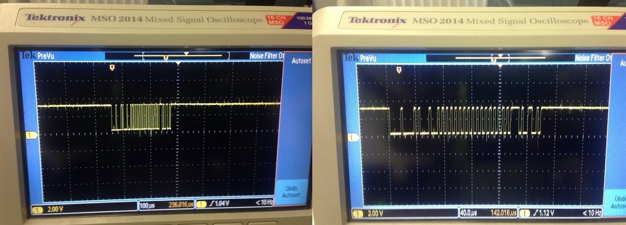
     If you look at the first picture you see the TX (yellow) and the RX (cyan). The RX pretty much follows the TX except the acknowledge bits. The ack field is a 2-bit field. As I mentioned in my earlier post I said my data is simply 0x55555555 of 4 bytes. You see bunch of 0101.... transitions followed by 15 bits of CRC and two bits of ACK and then followed by IFS.

     The second picture is a zoom-in view to show the ACK fields being replied by the receiver node.

     the third picture is how I hook them up using the boosterpack connectors. 


  • Here is another picture to show what is received by the receiver node.

  • Wonderful..I will try this setup to test my code. But regarding the UART prints, did u make any changes to the code as recommended by BP101 ? Could you share your UART function if it is different from BP101's recommendation ? Are those Zener diodes ?


    BP101 said:


    Schematic shows PD4,PD5 for UART2 is ICDI. CAN0 TXD/RXD are stated to be on the Booster Pack X6-9, X6-11 = MCU PA0, PA1 respectively. That would seem to suggest CAN0 is not on X11 header when JP4/5(||) otherwise why schematic notes only point out BP pins are then CAN0 and not bother to mention X11 header?

    Be sure to change UART0 to UART2 interrupt vector in (startup.ccs.c) or the UART2 (may) not function as intended.

  • Yes, you need to modify the InitConsole() function. I just changed from UART0 to UART2 and everywhere I see PA0/PA1 I changed to PD4/PD5. The diode is a simple rectify diode.
  • Wonderful. I will try ur setup and also my code. Thank you so much.
  • Hi Charles & All,

    UART2 seems to work fine using PD4/PD5. I have some questions regarding your setup.

    1) Is your resistor 3.3K ohm ? I could not see the colour code very clearly.

    2) Is it connected to GND or 3.3 V line ? I think it is 3.3V but just want to be sure of this. (https://electronics.stackexchange.com/questions/30564/is-a-can-enabled-microcontroller-sufficient-to-drive-a-can-bus)

    3) And  I need to short the GND of the 2 launchpads right ?

    Thanks.

  • Gowtham said:

    1) Is your resistor 3.3K ohm ? I could not see the colour code very clearly.

    Yes.

    Gowtham said:

    2) Is it connected to GND or 3.3 V line ? I think it is 3.3V but just want to be sure of this. (electronics.stackexchange.com/.../is-a-can-enabled-microcontroller-sufficient-to-drive-a-can-bus)

    Please see below schematic. I use 3.3V instead of 5V. Everything else is the same.

    Gowtham said:

    3) And  I need to short the GND of the 2 launchpads right ?

    Yes.

  • Attempted the setup but still no success. Hence, it could be my receive code. My receive code as below.

    Notable changes:

    1) // sCANMessage.ui32MsgLen =4

    2) // using uart2

    3) // Clk is 25000000 & bitrate is 500k are remained as default.

    I just want to know if my receive should work for your transmit code (can0_without_UART0.c). And then I can look into my hardware in detail. CAN0 external loopback is working fine for both my launchpads.

    //*****************************************************************************
    //
    // simple_rx.c - Example demonstrating simple CAN message reception.
    //
    // Copyright (c) 2010-2017 Texas Instruments Incorporated.  All rights reserved.
    // Software License Agreement
    //
    //   Redistribution and use in source and binary forms, with or without
    //   modification, are permitted provided that the following conditions
    //   are met:
    //
    //   Redistributions of source code must retain the above copyright
    //   notice, this list of conditions and the following disclaimer.
    //
    //   Redistributions in binary form must reproduce the above copyright
    //   notice, this list of conditions and the following disclaimer in the
    //   documentation and/or other materials provided with the
    //   distribution.
    //
    //   Neither the name of Texas Instruments Incorporated nor the names of
    //   its contributors may be used to endorse or promote products derived
    //   from this software without specific prior written permission.
    //
    // THIS SOFTWARE IS PROVIDED BY THE COPYRIGHT HOLDERS AND CONTRIBUTORS
    // "AS IS" AND ANY EXPRESS OR IMPLIED WARRANTIES, INCLUDING, BUT NOT
    // LIMITED TO, THE IMPLIED WARRANTIES OF MERCHANTABILITY AND FITNESS FOR
    // A PARTICULAR PURPOSE ARE DISCLAIMED. IN NO EVENT SHALL THE COPYRIGHT
    // OWNER OR CONTRIBUTORS BE LIABLE FOR ANY DIRECT, INDIRECT, INCIDENTAL,
    // SPECIAL, EXEMPLARY, OR CONSEQUENTIAL DAMAGES (INCLUDING, BUT NOT
    // LIMITED TO, PROCUREMENT OF SUBSTITUTE GOODS OR SERVICES; LOSS OF USE,
    // DATA, OR PROFITS; OR BUSINESS INTERRUPTION) HOWEVER CAUSED AND ON ANY
    // THEORY OF LIABILITY, WHETHER IN CONTRACT, STRICT LIABILITY, OR TORT
    // (INCLUDING NEGLIGENCE OR OTHERWISE) ARISING IN ANY WAY OUT OF THE USE
    // OF THIS SOFTWARE, EVEN IF ADVISED OF THE POSSIBILITY OF SUCH DAMAGE.
    //
    // This is part of revision 2.1.4.178 of the Tiva Firmware Development Package.
    //
    //*****************************************************************************
    
    #include <stdbool.h>
    #include <stdint.h>
    #include "inc/hw_can.h"
    #include "inc/hw_ints.h"
    #include "inc/hw_memmap.h"
    #include "inc/hw_types.h"
    #include "driverlib/can.h"
    #include "driverlib/gpio.h"
    #include "driverlib/interrupt.h"
    #include "driverlib/pin_map.h"
    #include "driverlib/sysctl.h"
    #include "driverlib/uart.h"
    #include "utils/uartstdio.h"
    
    //*****************************************************************************
    //
    //! \addtogroup can_examples_list
    //! <h1>Simple CAN RX (simple_rx)</h1>
    //!
    //! This example shows the basic setup of CAN in order to receive messages
    //! from the CAN bus.  The CAN peripheral is configured to receive messages
    //! with any CAN ID and then print the message contents to the console.
    //!
    //! This example uses the following peripherals and I/O signals.  You must
    //! review these and change as needed for your own board:
    //! - CAN0 peripheral
    //! - GPIO port B peripheral (for CAN0 pins)
    //! - CAN0RX - PB4
    //! - CAN0TX - PB5
    //!
    //! The following UART signals are configured only for displaying console
    //! messages for this example.  These are not required for operation of CAN.
    //! - GPIO port A peripheral (for UART0 pins)
    //! - UART0RX - PA0
    //! - UART0TX - PA1
    //!
    //! This example uses the following interrupt handlers.  To use this example
    //! in your own application you must add these interrupt handlers to your
    //! vector table.
    //! - INT_CAN0 - CANIntHandler
    //
    //*****************************************************************************
    
    //*****************************************************************************
    //
    // A counter that keeps track of the number of times the RX interrupt has
    // occurred, which should match the number of messages that were received.
    //
    //*****************************************************************************
    volatile uint32_t g_ui32MsgCount = 0;
    
    //*****************************************************************************
    //
    // A flag for the interrupt handler to indicate that a message was received.
    //
    //*****************************************************************************
    volatile bool g_bRXFlag = 0;
    
    //*****************************************************************************
    //
    // A flag to indicate that some reception error occurred.
    //
    //*****************************************************************************
    volatile bool g_bErrFlag = 0;
    
    //*****************************************************************************
    //
    // This function sets up UART0 to be used for a console to display information
    // as the example is running.
    //
    //*****************************************************************************
    void
    InitConsole(void)
    {
        //PD4/PD5
        // Enable GPIO port A which is used for UART0 pins.
        // TODO: change this to whichever GPIO port you are using.
        //
        SysCtlPeripheralEnable(SYSCTL_PERIPH_GPIOD);
    
        //
        // Configure the pin muxing for UART0 functions on port A0 and A1.
        // This step is not necessary if your part does not support pin muxing.
        // TODO: change this to select the port/pin you are using.
        //
        GPIOPinConfigure(GPIO_PD4_U2RX);
        GPIOPinConfigure(GPIO_PD5_U2TX);
    
        //
        // Enable UART0 so that we can configure the clock.
        //
        SysCtlPeripheralEnable(SYSCTL_PERIPH_UART2);
    
        //
        // Use the internal 16MHz oscillator as the UART clock source.
        //
        UARTClockSourceSet(UART2_BASE, UART_CLOCK_PIOSC);
    
        //
        // Select the alternate (UART) function for these pins.
        // TODO: change this to select the port/pin you are using.
        //
        GPIOPinTypeUART(GPIO_PORTD_BASE, GPIO_PIN_4 | GPIO_PIN_5);
    
        //
        // Initialize the UART for console I/O.
        //
        UARTStdioConfig(2, 115200, 16000000);
    }
    
    //*****************************************************************************
    //
    // This function is the interrupt handler for the CAN peripheral.  It checks
    // for the cause of the interrupt, and maintains a count of all messages that
    // have been received.
    //
    //*****************************************************************************
    void
    CANIntHandler(void)
    {
        uint32_t ui32Status;
    
        //
        // Read the CAN interrupt status to find the cause of the interrupt
        //
        ui32Status = CANIntStatus(CAN0_BASE, CAN_INT_STS_CAUSE);
    
        //
        // If the cause is a controller status interrupt, then get the status
        //
        if(ui32Status == CAN_INT_INTID_STATUS)
        {
            //
            // Read the controller status.  This will return a field of status
            // error bits that can indicate various errors.  Error processing
            // is not done in this example for simplicity.  Refer to the
            // API documentation for details about the error status bits.
            // The act of reading this status will clear the interrupt.
            //
            ui32Status = CANStatusGet(CAN0_BASE, CAN_STS_CONTROL);
    
            //
            // Set a flag to indicate some errors may have occurred.
            //
            g_bErrFlag = 1;
        }
    
        //
        // Check if the cause is message object 1, which what we are using for
        // receiving messages.
        //
        else if(ui32Status == 1)
        {
            //
            // Getting to this point means that the RX interrupt occurred on
            // message object 1, and the message reception is complete.  Clear the
            // message object interrupt.
            //
            CANIntClear(CAN0_BASE, 1);
    
            //
            // Increment a counter to keep track of how many messages have been
            // received.  In a real application this could be used to set flags to
            // indicate when a message is received.
            //
            g_ui32MsgCount++;
    
            //
            // Set flag to indicate received message is pending.
            //
            g_bRXFlag = 1;
    
            //
            // Since a message was received, clear any error flags.
            //
            g_bErrFlag = 0;
        }
    
        //
        // Otherwise, something unexpected caused the interrupt.  This should
        // never happen.
        //
        else
        {
            //
            // Spurious interrupt handling can go here.
            //
        }
        UARTprintf("Debug: triggered\n");
    }
    
    //*****************************************************************************
    //
    // Configure the CAN and enter a loop to receive CAN messages.
    //
    //*****************************************************************************
    int
    main(void)
    {
    #if defined(TARGET_IS_TM4C129_RA0) ||                                         \
        defined(TARGET_IS_TM4C129_RA1) ||                                         \
        defined(TARGET_IS_TM4C129_RA2)
        uint32_t ui32SysClock;
    #endif
    
        tCANMsgObject sCANMessage;
        uint8_t pui8MsgData[8];
    
        //
        // Set the clocking to run directly from the external crystal/oscillator.
        // TODO: The SYSCTL_XTAL_ value must be changed to match the value of the
        // crystal used on your board.
        //
    #if defined(TARGET_IS_TM4C129_RA0) ||                                         \
        defined(TARGET_IS_TM4C129_RA1) ||                                         \
        defined(TARGET_IS_TM4C129_RA2)
        ui32SysClock = SysCtlClockFreqSet((SYSCTL_XTAL_25MHZ |
                                           SYSCTL_OSC_MAIN |
                                           SYSCTL_USE_OSC)
                                           ,25000000);
    #else
        SysCtlClockSet(SYSCTL_SYSDIV_1 | SYSCTL_USE_OSC | SYSCTL_OSC_MAIN |
                       SYSCTL_XTAL_16MHZ);
    #endif
    
        //
        // Set up the serial console to use for displaying messages.  This is
        // just for this example program and is not needed for CAN operation.
        //
        InitConsole();
        UARTprintf("Debug: check console\n");
        //
        // For this example CAN0 is used with RX and TX pins on port B4 and B5.
        // The actual port and pins used may be different on your part, consult
        // the data sheet for more information.
        // GPIO port B needs to be enabled so these pins can be used.
        // TODO: change this to whichever GPIO port you are using
        //
        SysCtlPeripheralEnable(SYSCTL_PERIPH_GPIOA);
    
        //
        // Configure the GPIO pin muxing to select CAN0 functions for these pins.
        // This step selects which alternate function is available for these pins.
        // This is necessary if your part supports GPIO pin function muxing.
        // Consult the data sheet to see which functions are allocated per pin.
        // TODO: change this to select the port/pin you are using
        //
        GPIOPinConfigure(GPIO_PA0_CAN0RX);
        GPIOPinConfigure(GPIO_PA1_CAN0TX);
    
        //
        // Enable the alternate function on the GPIO pins.  The above step selects
        // which alternate function is available.  This step actually enables the
        // alternate function instead of GPIO for these pins.
        // TODO: change this to match the port/pin you are using
        //
        GPIOPinTypeCAN(GPIO_PORTA_BASE, GPIO_PIN_0 | GPIO_PIN_1);
    
        //
        // The GPIO port and pins have been set up for CAN.  The CAN peripheral
        // must be enabled.
        //
        SysCtlPeripheralEnable(SYSCTL_PERIPH_CAN0);
    
        //
        // Initialize the CAN controller
        //
        CANInit(CAN0_BASE);
    
        //
        // Set up the bit rate for the CAN bus.  This function sets up the CAN
        // bus timing for a nominal configuration.  You can achieve more control
        // over the CAN bus timing by using the function CANBitTimingSet() instead
        // of this one, if needed.
        // In this example, the CAN bus is set to 500 kHz.  In the function below,
        // the call to SysCtlClockGet() or ui32SysClock is used to determine the
        // clock rate that is used for clocking the CAN peripheral.  This can be
        // replaced with a  fixed value if you know the value of the system clock,
        // saving the extra function call.  For some parts, the CAN peripheral is
        // clocked by a fixed 8 MHz regardless of the system clock in which case
        // the call to SysCtlClockGet() or ui32SysClock should be replaced with
        // 8000000.  Consult the data sheet for more information about CAN
        // peripheral clocking.
        //
    #if defined(TARGET_IS_TM4C129_RA0) ||                                         \
        defined(TARGET_IS_TM4C129_RA1) ||                                         \
        defined(TARGET_IS_TM4C129_RA2)
        CANBitRateSet(CAN0_BASE, ui32SysClock, 500000);
    #else
        CANBitRateSet(CAN0_BASE, SysCtlClockGet(), 500000);
    #endif
    
        //
        // Enable interrupts on the CAN peripheral.  This example uses static
        // allocation of interrupt handlers which means the name of the handler
        // is in the vector table of startup code.  If you want to use dynamic
        // allocation of the vector table, then you must also call CANIntRegister()
        // here.
        //
        // CANIntRegister(CAN0_BASE, CANIntHandler); // if using dynamic vectors
        //
        CANIntEnable(CAN0_BASE, CAN_INT_MASTER | CAN_INT_ERROR | CAN_INT_STATUS);
    
        //
        // Enable the CAN interrupt on the processor (NVIC).
        //
        IntEnable(INT_CAN0);
    
        //
        // Enable the CAN for operation.
        //
        CANEnable(CAN0_BASE);
    
        //
        // Initialize a message object to be used for receiving CAN messages with
        // any CAN ID.  In order to receive any CAN ID, the ID and mask must both
        // be set to 0, and the ID filter enabled.
        //
        sCANMessage.ui32MsgID = 0;
        sCANMessage.ui32MsgIDMask = 0;
        sCANMessage.ui32Flags = MSG_OBJ_RX_INT_ENABLE | MSG_OBJ_USE_ID_FILTER;
        sCANMessage.ui32MsgLen = 4;
    
        //
        // Now load the message object into the CAN peripheral.  Once loaded the
        // CAN will receive any message on the bus, and an interrupt will occur.
        // Use message object 1 for receiving messages (this is not the same as
        // the CAN ID which can be any value in this example).
        //
        CANMessageSet(CAN0_BASE, 1, &sCANMessage, MSG_OBJ_TYPE_RX);
    
        //
        // Enter loop to process received messages.  This loop just checks a flag
        // that is set by the interrupt handler, and if set it reads out the
        // message and displays the contents.  This is not a robust method for
        // processing incoming CAN data and can only handle one messages at a time.
        // If many messages are being received close together, then some messages
        // may be dropped.  In a real application, some other method should be used
        // for queuing received messages in a way to ensure they are not lost.  You
        // can also make use of CAN FIFO mode which will allow messages to be
        // buffered before they are processed.
        //
        for(;;)
        {
            unsigned int uIdx;
    
            //
            // If the flag is set, that means that the RX interrupt occurred and
            // there is a message ready to be read from the CAN
            //
            if(g_bRXFlag)
            {
                //
                // Reuse the same message object that was used earlier to configure
                // the CAN for receiving messages.  A buffer for storing the
                // received data must also be provided, so set the buffer pointer
                // within the message object.
                //
                sCANMessage.pui8MsgData = pui8MsgData;
    
                //
                // Read the message from the CAN.  Message object number 1 is used
                // (which is not the same thing as CAN ID).  The interrupt clearing
                // flag is not set because this interrupt was already cleared in
                // the interrupt handler.
                //
                CANMessageGet(CAN0_BASE, 1, &sCANMessage, 0);
    
                //
                // Clear the pending message flag so that the interrupt handler can
                // set it again when the next message arrives.
                //
                g_bRXFlag = 0;
    
                //
                // Check to see if there is an indication that some messages were
                // lost.
                //
                if(sCANMessage.ui32Flags & MSG_OBJ_DATA_LOST)
                {
                    UARTprintf("CAN message loss detected\n");
                }
    
                //
                // Print out the contents of the message that was received.
                //
                UARTprintf("Msg ID=0x%08X len=%u data=0x",
                           sCANMessage.ui32MsgID, sCANMessage.ui32MsgLen);
                for(uIdx = 0; uIdx < sCANMessage.ui32MsgLen; uIdx++)
                {
                    UARTprintf("%02X ", pui8MsgData[uIdx]);
                }
                UARTprintf("total count=%u\n", g_ui32MsgCount);
            }
        }
    
        //
        // Return no errors
        //
        return(0);
    }
    

  • Hi,
    On your line 339, you didn't register the interrupt handler dynamically. I hope you had statically registered the CANIntHandler in the startup_ccs.c, correct?
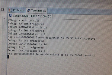
  • Finally. It is working. Thank you so much Charles & BP101. Now I can fully focus on my hardware setup  (transciever & etc) without doubting on the code.  Just one more question, it seems to me the receive is not continuos. Seems like I need to press the RESET button of the launchpad(Transmit side) everytime in order to transmit. This is not expected right ?

    Attached the scope cap & terminal output.

  • Hi Gowtham,

    Glad that you are making good progress.

    Isn't your transmitter in a while loop to keep transmitting data out?

    In your scope can you change the time scale so that you can see packets being transmitted continuously?
  • Perhaps I'm not understanding your question. In your scope for the receiver side you are showing count from 1..8 and keep continuing. What do you mean the receive is not continuous?
  • Hi Charles,

    How did you know line 339 there are no line numbers in code. Also curious as to why the 2nd ACK pulse wider than 1st pulse. Like to point out the status register compare code is not being masked by an (&) delimiter.  

    Perhaps more important to (&) mask return status when several bits in REG2 may transition, testing INTID status via (==) may not produce expected results. 

        //
        // Read the CAN interrupt status to find the cause of the interrupt
        //
        ui32Status = CANIntStatus(CAN0_BASE, CAN_INT_STS_CAUSE);
    
        //
        // If the cause is a controller status interrupt, then get the status
        //
        if(ui32Status //==
                    & CAN_INT_INTID_STATUS)

  • Hi BP101,

     I can see the line number. I'm taking a screenshot of the code posted by Godtham this morning.

    I think the image on the left is the TX pin of the transmitter and the image on the right is the RX pin of the transmitter. The RX pin will see the 2-bit ACK generated by the receiver. The TX pin will not see it because it is in recessive state. 

  • Hi Charles,

    Ok noticed that green code (listing) is missing from AM post, you must mean the attached file code line number. We can't scroll the web page back beyond the current top post to see what lies behind the left arrow, especially in edit mode. The TI web page browser is very difficult to work inside as we only see very 1st post in edit mode. Face Book has the right idea page scroll java handling, need to have MZ come visit TI.

    Checking INTSTS REG2 (CAN_INT_STS_CAUSE) seemingly clears REG5 INTID + bit 15 INT status.

    Either way REG 5 CANINT message object ID that caused the interrupt (0x0-0x20), bit 15 (0x8000h) interrupt pending. The INTID field has already been cleared by 1st reading STS REG2 into the ui32status variable and does not indicate a pending interrupt when (if) testing a fixed value against the ui32status. Seemingly we should 1st read REG5 CANINT into ui32IntStatus, later read REG2 INSTS into ui32IntStsCaus there by clearing the IRQ + message ID in REG5. Seemingly verifying the cause REG2 is not the same as verifying REG5 message ID that actually pended the IRQ.

    Curious does cause REG2 always update prior to REG5 setting bit 15 into IRQ pending?

    Register 5: CAN Interrupt (CANINT), offset 0x010
    This register indicates the source of the interrupt.

    If several interrupts are pending, the CAN Interrupt (CANINT) register points to the pending interrupt
    with the highest priority, disregarding the order in which the interrupts occurred. An interrupt remains
    pending until the CPU has cleared it. If the INTID field is not 0x0000 (the default) and the IE bit in
    the CANCTL register is set, the interrupt is active. The interrupt line remains active until the INTID
    field is cleared by reading the CANSTS register, or until the IE bit in the CANCTL register is cleared.

    Note: Reading the CAN Status (CANSTS) register clears the CAN Interrupt (CANINT) register,
    if it is pending.
  • Yep verified it's a greyed out posted code listing 11-13 9:31Am, no line numbers show up.

  • BP101 said:
    Yep verified it's a greyed out posted code listing 11-13 9:31Am, no line numbers show up.

    I see the same as BP, no line numbers or syntax highlighting, just a grey box with code.

    Robert

  • Robert Adsett said:
    I see the same as BP, no line numbers or syntax highlighting

    Oddly when entering the thread from very 1st post line #'s show until clicking right arrow, turn greyed with no line #'s on other pages. Except the code Charles copied above post show line #'s & green highlights, IE12..


  • Hi BP101, Robert,
    It is a bit weird now that I don't see the line number either. But I was pretty sure that yesterday I saw the line number. I have no idea what happened. I tried IE, Chrome and Firefox. In Firefox even the first very post has the grey box on the code. In IE and Chrome the code from yesterday is in white box but Firefox will display in grey box.
  • Exactly. CANMessageSet is within the while(1) loop. But it seems the transmission break after the first transmission (count =1). Now when I, press the RESET button of the launchpad, the program will reinitiate and it will transmit again (count =2). Then I had to press the RESET button again and again to transmit. I dont think this is expected. Right ?

    Some observations:

    1) ISR is not triggered at the Tx side

    2) ISR is triggered twice for each successful transmission at the RX side

    I also did an external loopback test with my tx on the transmit side. There seem to be continous transmission (from the scope cap). However, the ISR is not trigerred. I dont think this is expected. Correct me if I am wrong. Attached also the code:

    //*****************************************************************************
    //
    // simple_rx.c - Example demonstrating simple CAN message reception.
    //
    // Copyright (c) 2010-2017 Texas Instruments Incorporated.  All rights reserved.
    // Software License Agreement
    //
    //   Redistribution and use in source and binary forms, with or without
    //   modification, are permitted provided that the following conditions
    //   are met:
    //
    //   Redistributions of source code must retain the above copyright
    //   notice, this list of conditions and the following disclaimer.
    //
    //   Redistributions in binary form must reproduce the above copyright
    //   notice, this list of conditions and the following disclaimer in the
    //   documentation and/or other materials provided with the
    //   distribution.
    //
    //   Neither the name of Texas Instruments Incorporated nor the names of
    //   its contributors may be used to endorse or promote products derived
    //   from this software without specific prior written permission.
    //
    // THIS SOFTWARE IS PROVIDED BY THE COPYRIGHT HOLDERS AND CONTRIBUTORS
    // "AS IS" AND ANY EXPRESS OR IMPLIED WARRANTIES, INCLUDING, BUT NOT
    // LIMITED TO, THE IMPLIED WARRANTIES OF MERCHANTABILITY AND FITNESS FOR
    // A PARTICULAR PURPOSE ARE DISCLAIMED. IN NO EVENT SHALL THE COPYRIGHT
    // OWNER OR CONTRIBUTORS BE LIABLE FOR ANY DIRECT, INDIRECT, INCIDENTAL,
    // SPECIAL, EXEMPLARY, OR CONSEQUENTIAL DAMAGES (INCLUDING, BUT NOT
    // LIMITED TO, PROCUREMENT OF SUBSTITUTE GOODS OR SERVICES; LOSS OF USE,
    // DATA, OR PROFITS; OR BUSINESS INTERRUPTION) HOWEVER CAUSED AND ON ANY
    // THEORY OF LIABILITY, WHETHER IN CONTRACT, STRICT LIABILITY, OR TORT
    // (INCLUDING NEGLIGENCE OR OTHERWISE) ARISING IN ANY WAY OUT OF THE USE
    // OF THIS SOFTWARE, EVEN IF ADVISED OF THE POSSIBILITY OF SUCH DAMAGE.
    //
    // This is part of revision 2.1.4.178 of the Tiva Firmware Development Package.
    //
    //*****************************************************************************
    
    #include <stdbool.h>
    #include <stdint.h>
    #include "inc/hw_can.h"
    #include "inc/hw_ints.h"
    #include "inc/hw_memmap.h"
    #include "inc/hw_types.h"
    #include "driverlib/can.h"
    #include "driverlib/gpio.h"
    #include "driverlib/interrupt.h"
    #include "driverlib/pin_map.h"
    #include "driverlib/sysctl.h"
    #include "driverlib/uart.h"
    #include "utils/uartstdio.h"
    
    //*****************************************************************************
    //
    //! \addtogroup can_examples_list
    //! <h1>Simple CAN RX (simple_rx)</h1>
    //!
    //! This example shows the basic setup of CAN in order to receive messages
    //! from the CAN bus.  The CAN peripheral is configured to receive messages
    //! with any CAN ID and then print the message contents to the console.
    //!
    //! This example uses the following peripherals and I/O signals.  You must
    //! review these and change as needed for your own board:
    //! - CAN0 peripheral
    //! - GPIO port B peripheral (for CAN0 pins)
    //! - CAN0RX - PB4
    //! - CAN0TX - PB5
    //!
    //! The following UART signals are configured only for displaying console
    //! messages for this example.  These are not required for operation of CAN.
    //! - GPIO port A peripheral (for UART0 pins)
    //! - UART0RX - PA0
    //! - UART0TX - PA1
    //!
    //! This example uses the following interrupt handlers.  To use this example
    //! in your own application you must add these interrupt handlers to your
    //! vector table.
    //! - INT_CAN0 - CANIntHandler
    //
    //*****************************************************************************
    
    //*****************************************************************************
    //
    // A counter that keeps track of the number of times the RX interrupt has
    // occurred, which should match the number of messages that were received.
    //
    //*****************************************************************************
    volatile uint32_t g_ui32MsgCount = 0;
    
    //*****************************************************************************
    //
    // A flag for the interrupt handler to indicate that a message was received.
    //
    //*****************************************************************************
    volatile bool g_bRXFlag = 0;
    
    //*****************************************************************************
    //
    // A flag to indicate that some reception error occurred.
    //
    //*****************************************************************************
    volatile bool g_bErrFlag = 0;
    
    //*****************************************************************************
    //
    // This function sets up UART0 to be used for a console to display information
    // as the example is running.
    //
    //*****************************************************************************
    void
    InitConsole(void)
    {
        //PD4/PD5
        // Enable GPIO port A which is used for UART0 pins.
        // TODO: change this to whichever GPIO port you are using.
        //
        SysCtlPeripheralEnable(SYSCTL_PERIPH_GPIOD);
    
        //
        // Configure the pin muxing for UART0 functions on port A0 and A1.
        // This step is not necessary if your part does not support pin muxing.
        // TODO: change this to select the port/pin you are using.
        //
        GPIOPinConfigure(GPIO_PD4_U2RX);
        GPIOPinConfigure(GPIO_PD5_U2TX);
    
        //
        // Enable UART0 so that we can configure the clock.
        //
        SysCtlPeripheralEnable(SYSCTL_PERIPH_UART2);
    
        //
        // Use the internal 16MHz oscillator as the UART clock source.
        //
        UARTClockSourceSet(UART2_BASE, UART_CLOCK_PIOSC);
    
        //
        // Select the alternate (UART) function for these pins.
        // TODO: change this to select the port/pin you are using.
        //
        GPIOPinTypeUART(GPIO_PORTD_BASE, GPIO_PIN_4 | GPIO_PIN_5);
    
        //
        // Initialize the UART for console I/O.
        //
        UARTStdioConfig(2, 115200, 16000000);
    }
    
    //*****************************************************************************
    //
    // This function is the interrupt handler for the CAN peripheral.  It checks
    // for the cause of the interrupt, and maintains a count of all messages that
    // have been received.
    //
    //*****************************************************************************
    void
    CANIntHandler(void)
    {
        uint32_t ui32Status;
    
        //
        // Read the CAN interrupt status to find the cause of the interrupt
        //
        ui32Status = CANIntStatus(CAN0_BASE, CAN_INT_STS_CAUSE);
    
        //
        // If the cause is a controller status interrupt, then get the status
        //
        if(ui32Status == CAN_INT_INTID_STATUS)
        {
            //
            // Read the controller status.  This will return a field of status
            // error bits that can indicate various errors.  Error processing
            // is not done in this example for simplicity.  Refer to the
            // API documentation for details about the error status bits.
            // The act of reading this status will clear the interrupt.
            //
            ui32Status = CANStatusGet(CAN0_BASE, CAN_STS_CONTROL);
    
            //
            // Set a flag to indicate some errors may have occurred.
            //
            g_bErrFlag = 1;
        }
    
        //
        // Check if the cause is message object 1, which what we are using for
        // receiving messages.
        //
        else if(ui32Status == 1)
        {
            //
            // Getting to this point means that the RX interrupt occurred on
            // message object 1, and the message reception is complete.  Clear the
            // message object interrupt.
            //
            CANIntClear(CAN0_BASE, 1);
    
            //
            // Increment a counter to keep track of how many messages have been
            // received.  In a real application this could be used to set flags to
            // indicate when a message is received.
            //
            g_ui32MsgCount++;
    
            //
            // Set flag to indicate received message is pending.
            //
            g_bRXFlag = 1;
    
            //
            // Since a message was received, clear any error flags.
            //
            g_bErrFlag = 0;
        }
    
        //
        // Otherwise, something unexpected caused the interrupt.  This should
        // never happen.
        //
        else
        {
            //
            // Spurious interrupt handling can go here.
            //
        }
        UARTprintf("Debug: Rx_Int triggered\n");
        UARTprintf("Debug: CANIntStatus is %d\n",ui32Status);
    }
    
    //*****************************************************************************
    //
    // Configure the CAN and enter a loop to receive CAN messages.
    //
    //*****************************************************************************
    int
    main(void)
    {
    #if defined(TARGET_IS_TM4C129_RA0) ||                                         \
        defined(TARGET_IS_TM4C129_RA1) ||                                         \
        defined(TARGET_IS_TM4C129_RA2)
        uint32_t ui32SysClock;
    #endif
    
        tCANMsgObject sCANMessage;
        uint8_t pui8MsgData[8];
    
        //
        // Set the clocking to run directly from the external crystal/oscillator.
        // TODO: The SYSCTL_XTAL_ value must be changed to match the value of the
        // crystal used on your board.
        //
    #if defined(TARGET_IS_TM4C129_RA0) ||                                         \
        defined(TARGET_IS_TM4C129_RA1) ||                                         \
        defined(TARGET_IS_TM4C129_RA2)
        ui32SysClock = SysCtlClockFreqSet((SYSCTL_XTAL_25MHZ |
                                           SYSCTL_OSC_MAIN |
                                           SYSCTL_USE_OSC)
                                           ,25000000);
    #else
        SysCtlClockSet(SYSCTL_SYSDIV_1 | SYSCTL_USE_OSC | SYSCTL_OSC_MAIN |
                       SYSCTL_XTAL_16MHZ);
    #endif
    
        //
        // Set up the serial console to use for displaying messages.  This is
        // just for this example program and is not needed for CAN operation.
        //
        InitConsole();
        UARTprintf("Debug: check console\n");
        //
        // For this example CAN0 is used with RX and TX pins on port B4 and B5.
        // The actual port and pins used may be different on your part, consult
        // the data sheet for more information.
        // GPIO port B needs to be enabled so these pins can be used.
        // TODO: change this to whichever GPIO port you are using
        //
        SysCtlPeripheralEnable(SYSCTL_PERIPH_GPIOA);
    
        //
        // Configure the GPIO pin muxing to select CAN0 functions for these pins.
        // This step selects which alternate function is available for these pins.
        // This is necessary if your part supports GPIO pin function muxing.
        // Consult the data sheet to see which functions are allocated per pin.
        // TODO: change this to select the port/pin you are using
        //
        GPIOPinConfigure(GPIO_PA0_CAN0RX);
        GPIOPinConfigure(GPIO_PA1_CAN0TX);
    
        //
        // Enable the alternate function on the GPIO pins.  The above step selects
        // which alternate function is available.  This step actually enables the
        // alternate function instead of GPIO for these pins.
        // TODO: change this to match the port/pin you are using
        //
        GPIOPinTypeCAN(GPIO_PORTA_BASE, GPIO_PIN_0 | GPIO_PIN_1);
    
        //
        // The GPIO port and pins have been set up for CAN.  The CAN peripheral
        // must be enabled.
        //
        SysCtlPeripheralEnable(SYSCTL_PERIPH_CAN0);
    
        //
        // Initialize the CAN controller
        //
        CANInit(CAN0_BASE);
    
        //
        // Set up the bit rate for the CAN bus.  This function sets up the CAN
        // bus timing for a nominal configuration.  You can achieve more control
        // over the CAN bus timing by using the function CANBitTimingSet() instead
        // of this one, if needed.
        // In this example, the CAN bus is set to 500 kHz.  In the function below,
        // the call to SysCtlClockGet() or ui32SysClock is used to determine the
        // clock rate that is used for clocking the CAN peripheral.  This can be
        // replaced with a  fixed value if you know the value of the system clock,
        // saving the extra function call.  For some parts, the CAN peripheral is
        // clocked by a fixed 8 MHz regardless of the system clock in which case
        // the call to SysCtlClockGet() or ui32SysClock should be replaced with
        // 8000000.  Consult the data sheet for more information about CAN
        // peripheral clocking.
        //
    #if defined(TARGET_IS_TM4C129_RA0) ||                                         \
        defined(TARGET_IS_TM4C129_RA1) ||                                         \
        defined(TARGET_IS_TM4C129_RA2)
        CANBitRateSet(CAN0_BASE, ui32SysClock, 500000);
    #else
        CANBitRateSet(CAN0_BASE, SysCtlClockGet(), 500000);
    #endif
    
        //
        // Enable interrupts on the CAN peripheral.  This example uses static
        // allocation of interrupt handlers which means the name of the handler
        // is in the vector table of startup code.  If you want to use dynamic
        // allocation of the vector table, then you must also call CANIntRegister()
        // here.
        //
        CANIntRegister(CAN0_BASE, CANIntHandler); // if using dynamic vectors
        //
        CANIntEnable(CAN0_BASE, CAN_INT_MASTER | CAN_INT_ERROR | CAN_INT_STATUS);
    
        //
        // Enable the CAN interrupt on the processor (NVIC).
        //
        IntEnable(INT_CAN0);
    
        //
        // Enable the CAN for operation.
        //
        CANEnable(CAN0_BASE);
    
        //
        // Initialize a message object to be used for receiving CAN messages with
        // any CAN ID.  In order to receive any CAN ID, the ID and mask must both
        // be set to 0, and the ID filter enabled.
        //
        sCANMessage.ui32MsgID = 0;
        sCANMessage.ui32MsgIDMask = 0;
        sCANMessage.ui32Flags = MSG_OBJ_RX_INT_ENABLE | MSG_OBJ_USE_ID_FILTER;
        sCANMessage.ui32MsgLen = 4;
    
        //
        // Now load the message object into the CAN peripheral.  Once loaded the
        // CAN will receive any message on the bus, and an interrupt will occur.
        // Use message object 1 for receiving messages (this is not the same as
        // the CAN ID which can be any value in this example).
        //
        CANMessageSet(CAN0_BASE, 1, &sCANMessage, MSG_OBJ_TYPE_RX);
    
        //
        // Enter loop to process received messages.  This loop just checks a flag
        // that is set by the interrupt handler, and if set it reads out the
        // message and displays the contents.  This is not a robust method for
        // processing incoming CAN data and can only handle one messages at a time.
        // If many messages are being received close together, then some messages
        // may be dropped.  In a real application, some other method should be used
        // for queuing received messages in a way to ensure they are not lost.  You
        // can also make use of CAN FIFO mode which will allow messages to be
        // buffered before they are processed.
        //
        for(;;)
        {
            unsigned int uIdx;
    
            //
            // If the flag is set, that means that the RX interrupt occurred and
            // there is a message ready to be read from the CAN
            //
            if(g_bRXFlag)
            {
                //
                // Reuse the same message object that was used earlier to configure
                // the CAN for receiving messages.  A buffer for storing the
                // received data must also be provided, so set the buffer pointer
                // within the message object.
                //
                sCANMessage.pui8MsgData = pui8MsgData;
    
                //
                // Read the message from the CAN.  Message object number 1 is used
                // (which is not the same thing as CAN ID).  The interrupt clearing
                // flag is not set because this interrupt was already cleared in
                // the interrupt handler.
                //
                CANMessageGet(CAN0_BASE, 1, &sCANMessage, 0);
    
                //
                // Clear the pending message flag so that the interrupt handler can
                // set it again when the next message arrives.
                //
                g_bRXFlag = 0;
    
                //
                // Check to see if there is an indication that some messages were
                // lost.
                //
                if(sCANMessage.ui32Flags & MSG_OBJ_DATA_LOST)
                {
                    UARTprintf("CAN message loss detected\n");
                }
    
                //
                // Print out the contents of the message that was received.
                //
                UARTprintf("Msg ID=0x%08X len=%u data=0x",
                           sCANMessage.ui32MsgID, sCANMessage.ui32MsgLen);
                for(uIdx = 0; uIdx < sCANMessage.ui32MsgLen; uIdx++)
                {
                    UARTprintf("%02X ", pui8MsgData[uIdx]);
                }
                UARTprintf("total count=%u\n", g_ui32MsgCount);
            }
        }
    
        //
        // Return no errors
        //
        return(0);
    }
    

    //*****************************************************************************
    //
    // simple_tx.c - Example demonstrating simple CAN message transmission.
    //
    // Copyright (c) 2010-2017 Texas Instruments Incorporated.  All rights reserved.
    // Software License Agreement
    //
    //   Redistribution and use in source and binary forms, with or without
    //   modification, are permitted provided that the following conditions
    //   are met:
    //
    //   Redistributions of source code must retain the above copyright
    //   notice, this list of conditions and the following disclaimer.
    //
    //   Redistributions in binary form must reproduce the above copyright
    //   notice, this list of conditions and the following disclaimer in the
    //   documentation and/or other materials provided with the
    //   distribution.
    //
    //   Neither the name of Texas Instruments Incorporated nor the names of
    //   its contributors may be used to endorse or promote products derived
    //   from this software without specific prior written permission.
    //
    // THIS SOFTWARE IS PROVIDED BY THE COPYRIGHT HOLDERS AND CONTRIBUTORS
    // "AS IS" AND ANY EXPRESS OR IMPLIED WARRANTIES, INCLUDING, BUT NOT
    // LIMITED TO, THE IMPLIED WARRANTIES OF MERCHANTABILITY AND FITNESS FOR
    // A PARTICULAR PURPOSE ARE DISCLAIMED. IN NO EVENT SHALL THE COPYRIGHT
    // OWNER OR CONTRIBUTORS BE LIABLE FOR ANY DIRECT, INDIRECT, INCIDENTAL,
    // SPECIAL, EXEMPLARY, OR CONSEQUENTIAL DAMAGES (INCLUDING, BUT NOT
    // LIMITED TO, PROCUREMENT OF SUBSTITUTE GOODS OR SERVICES; LOSS OF USE,
    // DATA, OR PROFITS; OR BUSINESS INTERRUPTION) HOWEVER CAUSED AND ON ANY
    // THEORY OF LIABILITY, WHETHER IN CONTRACT, STRICT LIABILITY, OR TORT
    // (INCLUDING NEGLIGENCE OR OTHERWISE) ARISING IN ANY WAY OUT OF THE USE
    // OF THIS SOFTWARE, EVEN IF ADVISED OF THE POSSIBILITY OF SUCH DAMAGE.
    //
    // This is part of revision 2.1.4.178 of the Tiva Firmware Development Package.
    //
    //*****************************************************************************
    
    #include <stdbool.h>
    #include <stdint.h>
    #include "inc/hw_can.h"
    #include "inc/hw_ints.h"
    #include "inc/hw_memmap.h"
    #include "driverlib/can.h"
    #include "driverlib/gpio.h"
    #include "driverlib/interrupt.h"
    #include "driverlib/pin_map.h"
    #include "driverlib/sysctl.h"
    #include "driverlib/uart.h"
    #include "utils/uartstdio.h"
    
    //*****************************************************************************
    //
    //! \addtogroup can_examples_list
    //! <h1>Simple CAN TX (simple_tx)</h1>
    //!
    //! This example shows the basic setup of CAN in order to transmit messages
    //! on the CAN bus.  The CAN peripheral is configured to transmit messages
    //! with a specific CAN ID.  A message is then transmitted once per second,
    //! using a simple delay loop for timing.  The message that is sent is a 4
    //! byte message that contains an incrementing pattern.  A CAN interrupt
    //! handler is used to confirm message transmission and count the number of
    //! messages that have been sent.
    //!
    //! This example uses the following peripherals and I/O signals.  You must
    //! review these and change as needed for your own board:
    //! - CAN0 peripheral
    //! - GPIO Port B peripheral (for CAN0 pins)
    //! - CAN0RX - PB4
    //! - CAN0TX - PB5
    //!
    //! The following UART signals are configured only for displaying console
    //! messages for this example.  These are not required for operation of CAN.
    //! - GPIO port A peripheral (for UART0 pins)
    //! - UART0RX - PA0
    //! - UART0TX - PA1
    //!
    //! This example uses the following interrupt handlers.  To use this example
    //! in your own application you must add these interrupt handlers to your
    //! vector table.
    //! - INT_CAN0 - CANIntHandler
    //
    //*****************************************************************************
    
    //*****************************************************************************
    //
    // A counter that keeps track of the number of times the TX interrupt has
    // occurred, which should match the number of TX messages that were sent.
    //
    //*****************************************************************************
    volatile uint32_t g_ui32MsgCount = 0;
    
    //*****************************************************************************
    //
    // A flag to indicate that some transmission error occurred.
    //
    //*****************************************************************************
    volatile bool g_bErrFlag = 0;
    
    //*****************************************************************************
    //
    // This function sets up UART0 to be used for a console to display information
    // as the example is running.
    //
    //*****************************************************************************
    void
    InitConsole(void)
    {
        //PD4/PD5
        // Enable GPIO port A which is used for UART0 pins.
        // TODO: change this to whichever GPIO port you are using.
        //
        SysCtlPeripheralEnable(SYSCTL_PERIPH_GPIOD);
    
        //
        // Configure the pin muxing for UART0 functions on port A0 and A1.
        // This step is not necessary if your part does not support pin muxing.
        // TODO: change this to select the port/pin you are using.
        //
        GPIOPinConfigure(GPIO_PD4_U2RX);
        GPIOPinConfigure(GPIO_PD5_U2TX);
    
        //
        // Enable UART0 so that we can configure the clock.
        //
        SysCtlPeripheralEnable(SYSCTL_PERIPH_UART2);
    
        //
        // Use the internal 16MHz oscillator as the UART clock source.
        //
        UARTClockSourceSet(UART2_BASE, UART_CLOCK_PIOSC);
    
        //
        // Select the alternate (UART) function for these pins.
        // TODO: change this to select the port/pin you are using.
        //
        GPIOPinTypeUART(GPIO_PORTD_BASE, GPIO_PIN_4 | GPIO_PIN_5);
    
        //
        // Initialize the UART for console I/O.
        //
        UARTStdioConfig(2, 115200, 16000000);
    }
    
    //*****************************************************************************
    //
    // This function provides a 1 second delay using a simple polling method.
    //
    //*****************************************************************************
    void
    SimpleDelay(void)
    {
        //
        // Delay cycles for 1 second
        //
        SysCtlDelay(16000000 / 3);
    }
    
    //*****************************************************************************
    //
    // This function is the interrupt handler for the CAN peripheral.  It checks
    // for the cause of the interrupt, and maintains a count of all messages that
    // have been transmitted.
    //
    //*****************************************************************************
    void
    CANIntHandler(void)
    {
        uint32_t ui32Status;
    
        //
        // Read the CAN interrupt status to find the cause of the interrupt
        //
        ui32Status = CANIntStatus(CAN0_BASE, CAN_INT_STS_CAUSE);
    
        //
        // If the cause is a controller status interrupt, then get the status
        //
        if(ui32Status == CAN_INT_INTID_STATUS)
        {
            //
            // Read the controller status.  This will return a field of status
            // error bits that can indicate various errors.  Error processing
            // is not done in this example for simplicity.  Refer to the
            // API documentation for details about the error status bits.
            // The act of reading this status will clear the interrupt.  If the
            // CAN peripheral is not connected to a CAN bus with other CAN devices
            // present, then errors will occur and will be indicated in the
            // controller status.
            //
            ui32Status = CANStatusGet(CAN0_BASE, CAN_STS_CONTROL);
    
            //
            // Set a flag to indicate some errors may have occurred.
            //
            g_bErrFlag = 1;
        }
    
        //
        // Check if the cause is message object 1, which what we are using for
        // sending messages.
        //
        else if(ui32Status == 1)
        {
            //
            // Getting to this point means that the TX interrupt occurred on
            // message object 1, and the message TX is complete.  Clear the
            // message object interrupt.
            //
            CANIntClear(CAN0_BASE, 1);
    
            //
            // Increment a counter to keep track of how many messages have been
            // sent.  In a real application this could be used to set flags to
            // indicate when a message is sent.
            //
            g_ui32MsgCount++;
    
            //
            // Since the message was sent, clear any error flags.
            //
            g_bErrFlag = 0;
        }
    
        //
        // Otherwise, something unexpected caused the interrupt.  This should
        // never happen.
        //
        else
        {
            //
            // Spurious interrupt handling can go here.
            //
        }
        UARTprintf("Debug: Tx_Int triggered1\n");
        UARTprintf("Debug: CANIntStatus is %d\n",ui32Status);
    }
    
    //*****************************************************************************
    //
    // Configure the CAN and enter a loop to transmit periodic CAN messages.
    //
    //*****************************************************************************
    int
    main(void)
    {
    #if defined(TARGET_IS_TM4C129_RA0) ||                                         \
        defined(TARGET_IS_TM4C129_RA1) ||                                         \
        defined(TARGET_IS_TM4C129_RA2)
        uint32_t ui32SysClock;
    #endif
    
        tCANMsgObject sCANMessage;
        uint32_t ui32MsgData;
        uint8_t *pui8MsgData;
    
        pui8MsgData = (uint8_t *)&ui32MsgData;
    
        //
        // Set the clocking to run directly from the external crystal/oscillator.
        // TODO: The SYSCTL_XTAL_ value must be changed to match the value of the
        // crystal on your board.
        //
    #if defined(TARGET_IS_TM4C129_RA0) ||                                         \
        defined(TARGET_IS_TM4C129_RA1) ||                                         \
        defined(TARGET_IS_TM4C129_RA2)
        ui32SysClock = SysCtlClockFreqSet((SYSCTL_XTAL_25MHZ | SYSCTL_OSC_MAIN |SYSCTL_USE_OSC), 25000000);
    #else
        SysCtlClockSet(SYSCTL_SYSDIV_1 | SYSCTL_USE_OSC | SYSCTL_OSC_MAIN |
                       SYSCTL_XTAL_16MHZ);
    #endif
    
        //
        // Set up the serial console to use for displaying messages.  This is
        // just for this example program and is not needed for CAN operation.
        //
        InitConsole();
        UARTprintf("Debug: console check\n ");
        //
        // For this example CAN0 is used with RX and TX pins on port B4 and B5.
        // The actual port and pins used may be different on your part, consult
        // the data sheet for more information.
        // GPIO port B needs to be enabled so these pins can be used.
        // TODO: change this to whichever GPIO port you are using
        //
        SysCtlPeripheralEnable(SYSCTL_PERIPH_GPIOA);
    
        //
        // Configure the GPIO pin muxing to select CAN0 functions for these pins.
        // This step selects which alternate function is available for these pins.
        // This is necessary if your part supports GPIO pin function muxing.
        // Consult the data sheet to see which functions are allocated per pin.
        // TODO: change this to select the port/pin you are using
        //
        GPIOPinConfigure(GPIO_PA0_CAN0RX);
        GPIOPinConfigure(GPIO_PA1_CAN0TX);
    
        //
        // Enable the alternate function on the GPIO pins.  The above step selects
        // which alternate function is available.  This step actually enables the
        // alternate function instead of GPIO for these pins.
        // TODO: change this to match the port/pin you are using
        //
        GPIOPinTypeCAN(GPIO_PORTA_BASE, GPIO_PIN_0 | GPIO_PIN_1);
    
        //
        // The GPIO port and pins have been set up for CAN.  The CAN peripheral
        // must be enabled.
        //
        SysCtlPeripheralEnable(SYSCTL_PERIPH_CAN0);
    
        //
        // Initialize the CAN controller
        //
        CANInit(CAN0_BASE);
    
        //
        // Set up the bit rate for the CAN bus.  This function sets up the CAN
        // bus timing for a nominal configuration.  You can achieve more control
        // over the CAN bus timing by using the function CANBitTimingSet() instead
        // of this one, if needed.
        // In this example, the CAN bus is set to 500 kHz.  In the function below,
        // the call to SysCtlClockGet() or ui32SysClock is used to determine the
        // clock rate that is used for clocking the CAN peripheral.  This can be
        // replaced with a  fixed value if you know the value of the system clock,
        // saving the extra function call.  For some parts, the CAN peripheral is
        // clocked by a fixed 8 MHz regardless of the system clock in which case
        // the call to SysCtlClockGet() or ui32SysClock should be replaced with
        // 8000000.  Consult the data sheet for more information about CAN
        // peripheral clocking.
        //
    #if defined(TARGET_IS_TM4C129_RA0) ||                                         \
        defined(TARGET_IS_TM4C129_RA1) ||                                         \
        defined(TARGET_IS_TM4C129_RA2)
        CANBitRateSet(CAN0_BASE, ui32SysClock, 500000);
    #else
        CANBitRateSet(CAN0_BASE, SysCtlClockGet(), 500000);
    #endif
    
        //
        // Enable interrupts on the CAN peripheral.  This example uses static
        // allocation of interrupt handlers which means the name of the handler
        // is in the vector table of startup code.  If you want to use dynamic
        // allocation of the vector table, then you must also call CANIntRegister()
        // here.
        //
        // CANIntRegister(CAN0_BASE, CANIntHandler); // if using dynamic vectors
        //
        CANIntEnable(CAN0_BASE, CAN_INT_MASTER | CAN_INT_ERROR | CAN_INT_STATUS);
    
        //
        // Enable the CAN interrupt on the processor (NVIC).
        //
        IntEnable(INT_CAN0);
    
        //
        // Enable the CAN for operation.
        //
        CANEnable(CAN0_BASE);
    
        //
        // Initialize the message object that will be used for sending CAN
        // messages.  The message will be 4 bytes that will contain an incrementing
        // value.  Initially it will be set to 0.
        //
        ui32MsgData = 0;
        sCANMessage.ui32MsgID = 1;
        sCANMessage.ui32MsgIDMask = 0;
        sCANMessage.ui32Flags = MSG_OBJ_TX_INT_ENABLE;
        sCANMessage.ui32MsgLen = sizeof(pui8MsgData);
        sCANMessage.pui8MsgData = pui8MsgData;
    
        //
        // Enter loop to send messages.  A new message will be sent once per
        // second.  The 4 bytes of message content will be treated as an uint32_t
        // and incremented by one each time.
        //
        while(1)
        {
            //
            // Print a message to the console showing the message count and the
            // contents of the message being sent.
            //
    /*        UARTprintf("Sending msg: 0x%02X %02X %02X %02X",
                       pui8MsgData[0], pui8MsgData[1], pui8MsgData[2],
                       pui8MsgData[3]); */
            ui32MsgData = 0x55555544;
    
            //
            // Send the CAN message using object number 1 (not the same thing as
            // CAN ID, which is also 1 in this example).  This function will cause
            // the message to be transmitted right away.
            //
            CANMessageSet(CAN0_BASE, 1, &sCANMessage, MSG_OBJ_TYPE_TX);
    
            //
            // Now wait 1 second before continuing
            //
            SimpleDelay();
    
            //
            // Check the error flag to see if errors occurred
            //
            if(g_bErrFlag)
            {
    //            UARTprintf(" error - cable connected?\n");
            	while(1);
            }
            else
            {
                //
                // If no errors then print the count of message sent
                //
    //            UARTprintf(" total count = %u\n", g_ui32MsgCount);
            }
    
            //
            // Increment the value in the message data.
            //
            //ui32MsgData++;
        }
    
        //
        // Return no errors
        //
        return(0);
    }
    

  • In the tx.c code you attached you have the CANIntRegister() commented out.

       //

       // Enable interrupts on the CAN peripheral.  This example uses static

       // allocation of interrupt handlers which means the name of the handler

       // is in the vector table of startup code.  If you want to use dynamic

       // allocation of the vector table, then you must also call CANIntRegister()

       // here.

       //

       // CANIntRegister(CAN0_BASE, CANIntHandler); // if using dynamic vectors

       //

       CANIntEnable(CAN0_BASE, CAN_INT_MASTER | CAN_INT_ERROR | CAN_INT_STATUS);

    If you don't register the interrupt handler dynamically by uncommenting the CANIntRegister shown above then you will need to statically declare the interrupt handler in the startup_ccs.c. Please see below the CANIntRegister declaration.  You need to do one or the other (dynamically or statically) 

    
    //*****************************************************************************
    //
    // Forward declaration of the default fault handlers.
    //
    //*****************************************************************************
    void ResetISR(void);
    static void NmiSR(void);
    static void FaultISR(void);
    static void IntDefaultHandler(void);
    static void CANIntHandler(void);
    
    
    //*****************************************************************************
    //
    // External declaration for the reset handler that is to be called when the
    // processor is started
    //
    //*****************************************************************************
    extern void _c_int00(void);
    
    //*****************************************************************************
    //
    // Linker variable that marks the top of the stack.
    //
    //*****************************************************************************
    extern uint32_t __STACK_TOP;
    
    //*****************************************************************************
    //
    // The vector table.  Note that the proper constructs must be placed on this to
    // ensure that it ends up at physical address 0x0000.0000 or at the start of
    // the program if located at a start address other than 0.
    //
    //*****************************************************************************
    #pragma DATA_SECTION(g_pfnVectors, ".intvecs")
    void (* const g_pfnVectors[])(void) =
    {
        (void (*)(void))((uint32_t)&__STACK_TOP),
                                                // The initial stack pointer
        ResetISR,                               // The reset handler
        NmiSR,                                  // The NMI handler
        FaultISR,                               // The hard fault handler
        IntDefaultHandler,                      // The MPU fault handler
        IntDefaultHandler,                      // The bus fault handler
        IntDefaultHandler,                      // The usage fault handler
        0,                                      // Reserved
        0,                                      // Reserved
        0,                                      // Reserved
        0,                                      // Reserved
        IntDefaultHandler,                      // SVCall handler
        IntDefaultHandler,                      // Debug monitor handler
        0,                                      // Reserved
        IntDefaultHandler,                      // The PendSV handler
        IntDefaultHandler,                      // The SysTick handler
        IntDefaultHandler,                      // GPIO Port A
        IntDefaultHandler,                      // GPIO Port B
        IntDefaultHandler,                      // GPIO Port C
        IntDefaultHandler,                      // GPIO Port D
        IntDefaultHandler,                      // GPIO Port E
        IntDefaultHandler,                      // UART0 Rx and Tx
        IntDefaultHandler,                      // UART1 Rx and Tx
        IntDefaultHandler,                      // SSI0 Rx and Tx
        IntDefaultHandler,                      // I2C0 Master and Slave
        IntDefaultHandler,                      // PWM Fault
        IntDefaultHandler,                      // PWM Generator 0
        IntDefaultHandler,                      // PWM Generator 1
        IntDefaultHandler,                      // PWM Generator 2
        IntDefaultHandler,                      // Quadrature Encoder 0
        IntDefaultHandler,                      // ADC Sequence 0
        IntDefaultHandler,                      // ADC Sequence 1
        IntDefaultHandler,                      // ADC Sequence 2
        IntDefaultHandler,                      // ADC Sequence 3
        IntDefaultHandler,                      // Watchdog timer
        IntDefaultHandler,                      // Timer 0 subtimer A
        IntDefaultHandler,                      // Timer 0 subtimer B
        IntDefaultHandler,                      // Timer 1 subtimer A
        IntDefaultHandler,                      // Timer 1 subtimer B
        IntDefaultHandler,                      // Timer 2 subtimer A
        IntDefaultHandler,                      // Timer 2 subtimer B
        IntDefaultHandler,                      // Analog Comparator 0
        IntDefaultHandler,                      // Analog Comparator 1
        IntDefaultHandler,                      // Analog Comparator 2
        IntDefaultHandler,                      // System Control (PLL, OSC, BO)
        IntDefaultHandler,                      // FLASH Control
        IntDefaultHandler,                      // GPIO Port F
        IntDefaultHandler,                      // GPIO Port G
        IntDefaultHandler,                      // GPIO Port H
        IntDefaultHandler,                      // UART2 Rx and Tx
        IntDefaultHandler,                      // SSI1 Rx and Tx
        IntDefaultHandler,                      // Timer 3 subtimer A
        IntDefaultHandler,                      // Timer 3 subtimer B
        IntDefaultHandler,                      // I2C1 Master and Slave
    	CANIntHandler,                      // CAN0
        IntDefaultHandler,                      // CAN1
        IntDefaultHandler,                      // Ethernet
        IntDefaultHandler,                      // Hibernate
        IntDefaultHandler,                      // USB0
        IntDefaultHandler,                      // PWM Generator 3
        IntDefaultHandler,                      // uDMA Software Transfer
        IntDefaultHandler,                      // uDMA Error
        IntDefaultHandler,                      // ADC1 Sequence 0
        IntDefaultHandler,                      // ADC1 Sequence 1
        IntDefaultHandler,                      // ADC1 Sequence 2
        IntDefaultHandler,                      // ADC1 Sequence 3
        IntDefaultHandler,                      // External Bus Interface 0
        IntDefaultHandler,                      // GPIO Port J
        IntDefaultHandler,                      // GPIO Port K
        IntDefaultHandler,                      // GPIO Port L
        IntDefaultHandler,                      // SSI2 Rx and Tx
        IntDefaultHandler,                      // SSI3 Rx and Tx
        IntDefaultHandler,                      // UART3 Rx and Tx
        IntDefaultHandler,                      // UART4 Rx and Tx
        IntDefaultHandler,                      // UART5 Rx and Tx
        IntDefaultHandler,                      // UART6 Rx and Tx
        IntDefaultHandler,                      // UART7 Rx and Tx
        IntDefaultHandler,                      // I2C2 Master and Slave
        IntDefaultHandler,                      // I2C3 Master and Slave
        IntDefaultHandler,                      // Timer 4 subtimer A
        IntDefaultHandler,                      // Timer 4 subtimer B
        IntDefaultHandler,                      // Timer 5 subtimer A
        IntDefaultHandler,                      // Timer 5 subtimer B
        IntDefaultHandler,                      // FPU
        0,                                      // Reserved
        0,                                      // Reserved
        IntDefaultHandler,                      // I2C4 Master and Slave
        IntDefaultHandler,                      // I2C5 Master and Slave
        IntDefaultHandler,                      // GPIO Port M
        IntDefaultHandler,                      // GPIO Port N
        0,                                      // Reserved
        IntDefaultHandler,                      // Tamper
        IntDefaultHandler,                      // GPIO Port P (Summary or P0)
        IntDefaultHandler,                      // GPIO Port P1
        IntDefaultHandler,                      // GPIO Port P2
        IntDefaultHandler,                      // GPIO Port P3
        IntDefaultHandler,                      // GPIO Port P4
        IntDefaultHandler,                      // GPIO Port P5
        IntDefaultHandler,                      // GPIO Port P6
        IntDefaultHandler,                      // GPIO Port P7
        IntDefaultHandler,                      // GPIO Port Q (Summary or Q0)
        IntDefaultHandler,                      // GPIO Port Q1
        IntDefaultHandler,                      // GPIO Port Q2
        IntDefaultHandler,                      // GPIO Port Q3
        IntDefaultHandler,                      // GPIO Port Q4
        IntDefaultHandler,                      // GPIO Port Q5
        IntDefaultHandler,                      // GPIO Port Q6
        IntDefaultHandler,                      // GPIO Port Q7
        IntDefaultHandler,                      // GPIO Port R
        IntDefaultHandler,                      // GPIO Port S
        IntDefaultHandler,                      // SHA/MD5 0
        IntDefaultHandler,                      // AES 0
        IntDefaultHandler,                      // DES3DES 0
        IntDefaultHandler,                      // LCD Controller 0
        IntDefaultHandler,                      // Timer 6 subtimer A
        IntDefaultHandler,                      // Timer 6 subtimer B
        IntDefaultHandler,                      // Timer 7 subtimer A
        IntDefaultHandler,                      // Timer 7 subtimer B
        IntDefaultHandler,                      // I2C6 Master and Slave
        IntDefaultHandler,                      // I2C7 Master and Slave
        IntDefaultHandler,                      // HIM Scan Matrix Keyboard 0
        IntDefaultHandler,                      // One Wire 0
        IntDefaultHandler,                      // HIM PS/2 0
        IntDefaultHandler,                      // HIM LED Sequencer 0
        IntDefaultHandler,                      // HIM Consumer IR 0
        IntDefaultHandler,                      // I2C8 Master and Slave
        IntDefaultHandler,                      // I2C9 Master and Slave
        IntDefaultHandler                       // GPIO Port T
    };


  • Not sure why I always have a blind eye for CANIntRegister() . Really sorry about that. Thank you for the detailed explaination on how to declare CANIntRegister statically. The transmit-receive is working fine now.

    Should the CANIntHandler triggered twice for every receive ? (please refer to my previous Rx_ terminal output).