Part Number: EK-TM4C129EXL
Other Parts Discussed in Thread: EK-TM4C1294XL, TPS2052, TPS2052B
Hi All. I am very new to CAN Bus protocol and TM4C. I am given a task to transmit CAN messages from 1 TM4C129EXL to another TM4C129EXL launchpad. Since I am new to this and I need to start from somewhere, I have decided to adapt the code and the hardware from the link below : http://ohm.ninja/tiva-c-series-can-bus-with-mcp2551/ and also by refering to the sample code from C:\ti\TivaWare_C_Series-2.1.4.178\examples\peripherals\can.
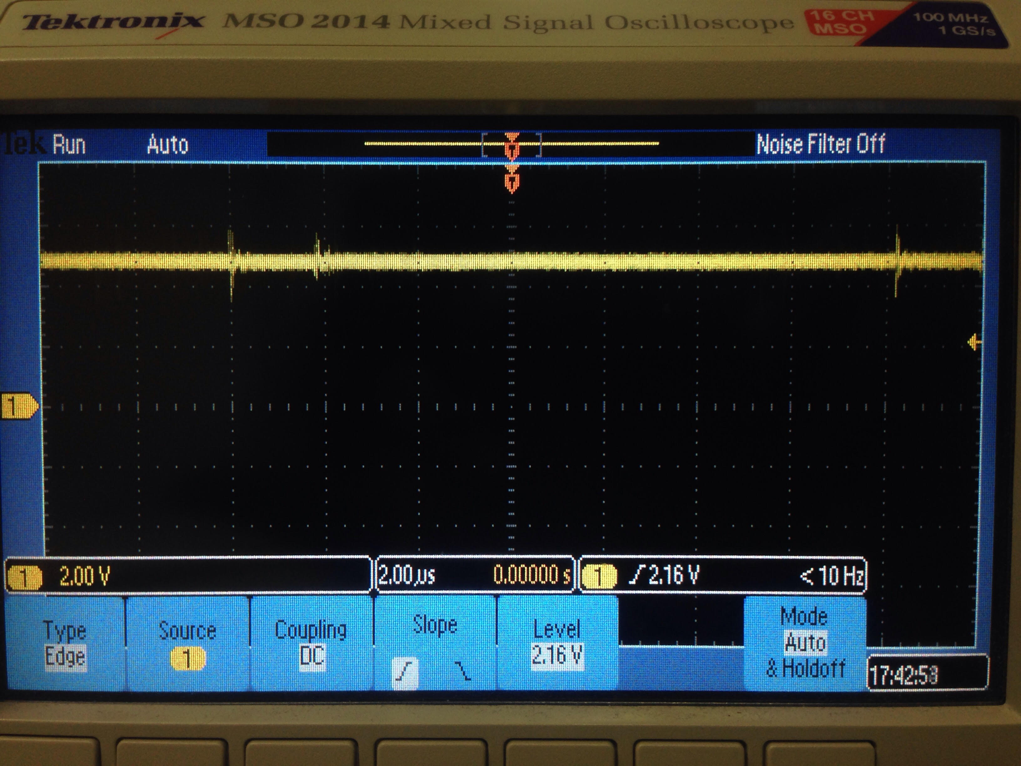
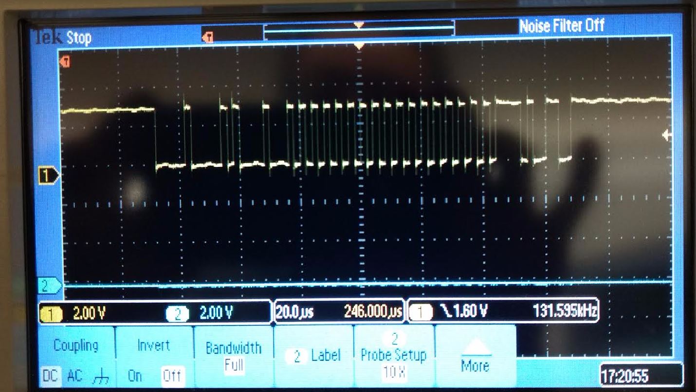
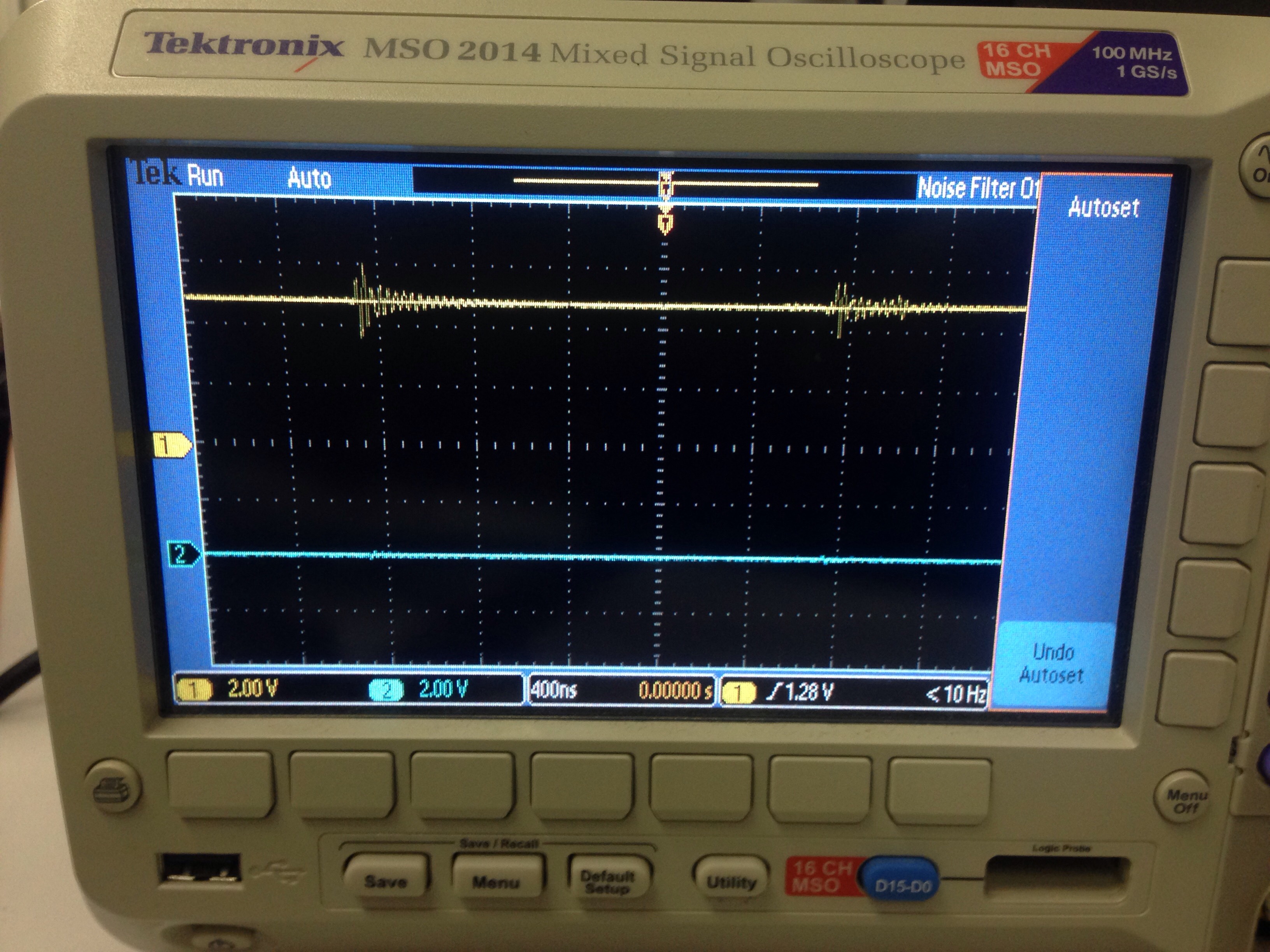
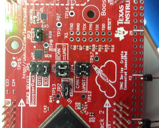
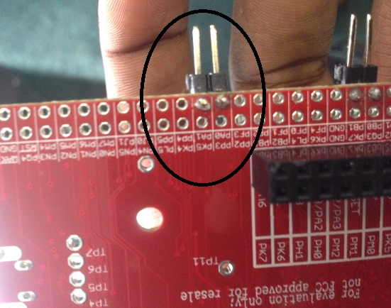
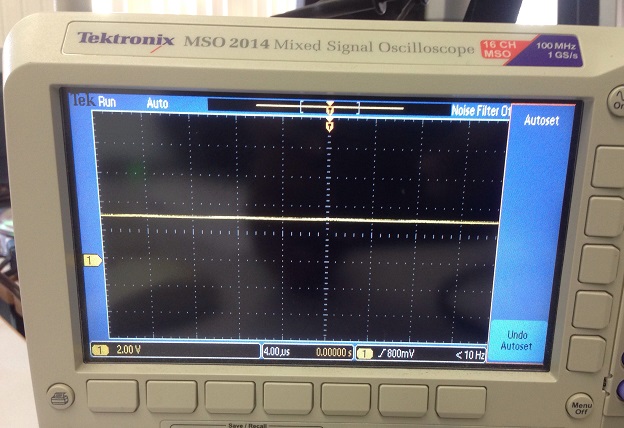
I have added severel UARTprintf to the void CANIntHandler(void) to help my debugging. I have also used the oscilloscope to check CANH,CANL and TX but there are no output (hence, scope caps are not attached in this post). The JP4 and JP5 jumpers are in default configuration since CAN1 is used instead of CAN0. Please do assist.
Attached is my code for Master:
#include <stdbool.h>
#include <stdint.h>
#include <math.h>
#include "inc/hw_memmap.h"
#include "inc/hw_types.h"
#include "inc/hw_can.h"
#include "inc/hw_ints.h"
#include "driverlib/can.h"
#include "driverlib/interrupt.h"
#include "driverlib/sysctl.h"
#include "driverlib/gpio.h"
#include "driverlib/uart.h"
#include "driverlib/pin_map.h"
#include "utils/uartstdio.h"
#define PI 3.14159265359f
volatile bool errFlag = 0; // transmission error flag
unsigned int sysClock; // clockspeed in hz
void delay(unsigned int milliseconds) {
SysCtlDelay((sysClock / 3) * (milliseconds / 1000.0f));
}
// CAN interrupt handler
void CANIntHandler(void) {
unsigned long status = CANIntStatus(CAN1_BASE, CAN_INT_STS_CAUSE); // read interrupt status
UARTprintf("Triggered\n");
if(status == CAN_INT_INTID_STATUS) { // controller status interrupt
status = CANStatusGet(CAN1_BASE, CAN_STS_CONTROL); // read back error bits, do something with them?
errFlag = 1;
UARTprintf("Triggered1\n");
} else if(status == 1) { // message object 1
CANIntClear(CAN1_BASE, 1); // clear interrupt
errFlag = 0; // clear any error flags
UARTprintf("Triggered2\n");
} else { // should never happen
UARTprintf("Unexpected CAN bus interrupt\n");
UARTprintf("Error is-- %lu\n",status);
}
}
int main(void) {
tCANMsgObject msg; // the CAN message object
unsigned int msgData; // the message data is four bytes long which we can allocate as an int32
unsigned char *msgDataPtr = (unsigned char *)&msgData; // make a pointer to msgData so we can access individual bytes
// Run from the PLL at 120 MHz.
sysClock = SysCtlClockFreqSet((SYSCTL_XTAL_25MHZ | SYSCTL_OSC_MAIN | SYSCTL_USE_PLL | SYSCTL_CFG_VCO_480), 120000000);
// Set up debugging UART
SysCtlPeripheralEnable(SYSCTL_PERIPH_GPIOA); // enable UART0 GPIO peripheral
SysCtlPeripheralEnable(SYSCTL_PERIPH_UART0);
GPIOPinConfigure(GPIO_PA0_U0RX);
GPIOPinConfigure(GPIO_PA1_U0TX);
GPIOPinTypeUART(GPIO_PORTA_BASE, GPIO_PIN_0 | GPIO_PIN_1);
UARTStdioConfig(0, 115200, sysClock); // 115200 baud
// Set up CAN1
SysCtlPeripheralEnable(SYSCTL_PERIPH_GPIOB); // enable CAN1 GPIO peripheral
GPIOPinConfigure(GPIO_PB0_CAN1RX);
GPIOPinConfigure(GPIO_PB1_CAN1TX);
GPIOPinTypeCAN(GPIO_PORTB_BASE, GPIO_PIN_0 | GPIO_PIN_1);
SysCtlPeripheralEnable(SYSCTL_PERIPH_CAN1);
CANInit(CAN1_BASE);
CANBitRateSet(CAN1_BASE, sysClock, 500000);
CANIntRegister(CAN1_BASE, CANIntHandler); // use dynamic vector table allocation
CANIntEnable(CAN1_BASE, CAN_INT_MASTER | CAN_INT_ERROR | CAN_INT_STATUS);
IntEnable(INT_CAN1);
CANEnable(CAN1_BASE);
// Set up msg object
msgData = 0;
msg.ui32MsgID = 1;
msg.ui32MsgIDMask = 0;
msg.ui32Flags = MSG_OBJ_TX_INT_ENABLE;
msg.ui32MsgLen = sizeof(msgDataPtr);
msg.pui8MsgData = msgDataPtr;
unsigned int t = 0; // loop counter
float freq = 0.3; // frequency scaler
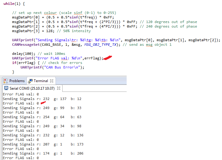
while(1) {
// set up next colour (scale sinf (0-1) to 0-255)
msgDataPtr[0] = (0.5 + 0.5*sinf(t*freq)) * 0xFF;
msgDataPtr[1] = (0.5 + 0.5*sinf(t*freq + (2*PI/3))) * 0xFF; // 120 degrees out of phase
msgDataPtr[2] = (0.5 + 0.5*sinf(t*freq + (4*PI/3))) * 0xFF; // 240 degrees out of phase
msgDataPtr[3] = 128; // 50% intensity
UARTprintf("Sending colour\tr: %d\tg: %d\tb: %d\n", msgDataPtr[0], msgDataPtr[1], msgDataPtr[2]); // write colour to UART for debugging
CANMessageSet(CAN1_BASE, 1, &msg, MSG_OBJ_TYPE_TX); // send as msg object 1
delay(100); // wait 100ms
if(errFlag) { // check for errors
UARTprintf("CAN Bus Error\n");
}
t++; // overflow is fine
}
return 0;
}
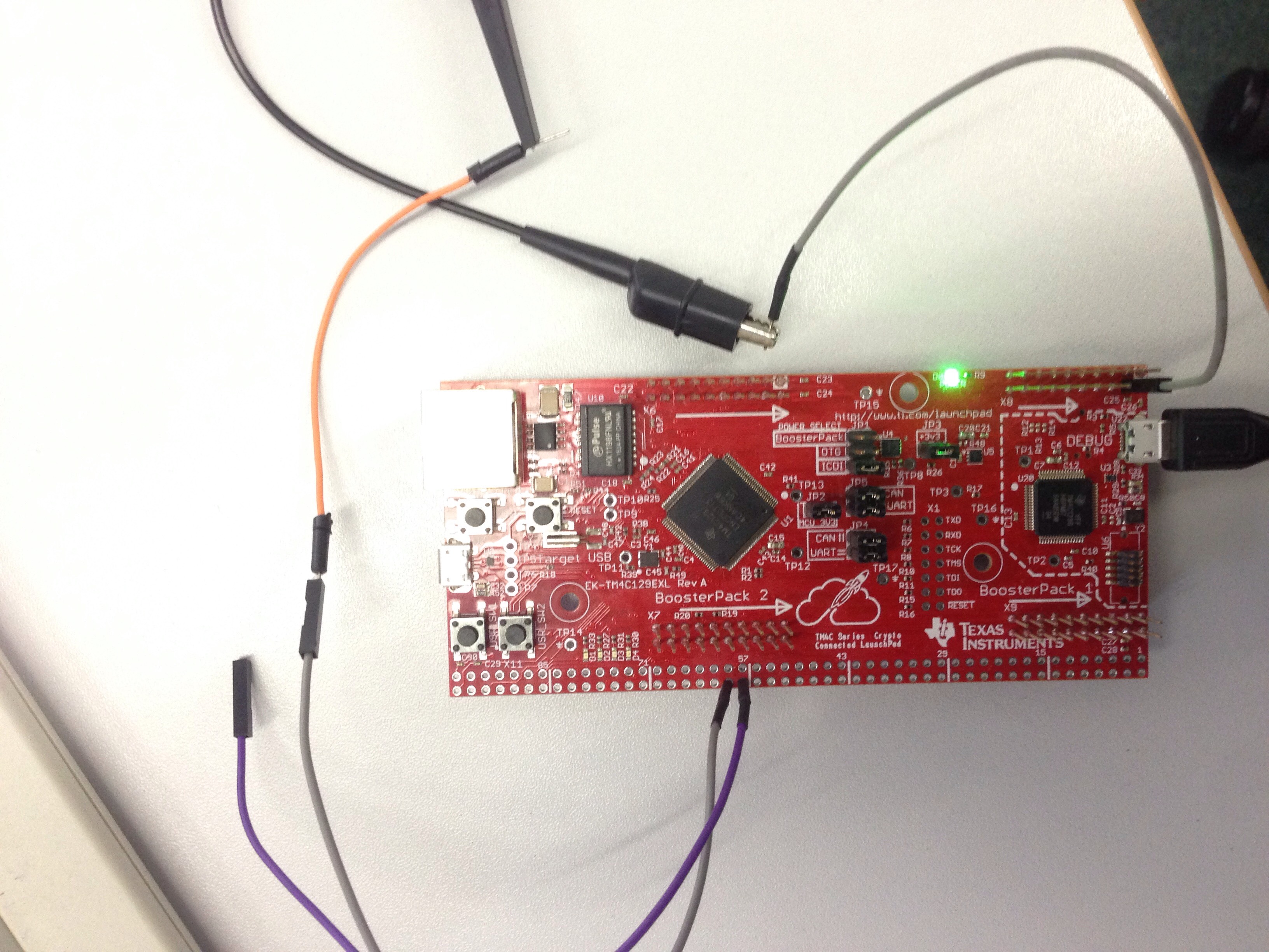
Attached is my circuit diagram: 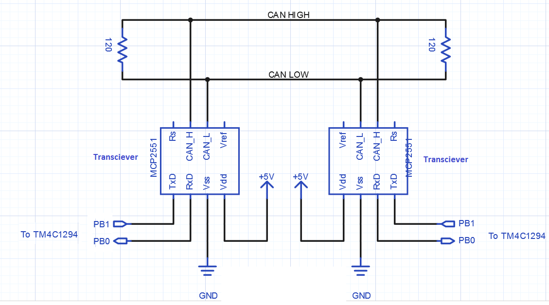

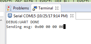
Attached is the output from the terminal: