This thread has been locked.

If you have a related question, please click the "Ask a related question" button in the top right corner. The newly created question will be automatically linked to this question.

CCS/TM4C123GH6PM: How to partition the memory as per need

Part Number: TM4C123GH6PM

Tool/software: Code Composer Studio

Hi All,

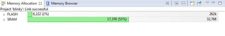
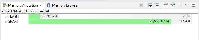
I am trying to run a particular code which needs more than 32,768 bytes.

Is there some way I can use the blank memory (93% of FLASH 262kbytes) as shown in the image below?

Is there a way to partition the memory as per user's need? If yes, which file should I update?

Thanks in advance for your help

  • Rohan Chawhan said:
    Is there some way I can use the blank memory (93% of FLASH 262kbytes) as shown in the image below?

    Your post reveals - but does not explain - that the 32KB memory limit describes MCU's SRAM.     The blank memory is FLASH - which cannot serve the same role as SRAM.

    You speak to, "partitioning" - which is possible - yet, "Fails to extend SRAM beyond the MCU's listed (32KB) limit."    

    Instead - would not "focusing your attention" more upon which variables "truly/really" demand, "Placement w/in SRAM" - prove a better path?    To assist such focus - might you re-examine your criteria for, "Placing and/or Declaring/Defining objects - so that they (likely) become SRAM resident?"    (for example, if a function's parameter block (variable) is unlikely to change, you may "hard code it" - and escape resulting SRAM usage.)

    You may also consider MCU's EEProm - yet penalties accrue - and errata notes are many.   (and foreboding)    External EEProms prove faster, easier & more robust.    (thus superior!)    This vendor produces a rather unique, external RAM device (fram) - your search enables its consideration.      

    MCU's Flash is a (less likely) alternative - may allow (some) variable storage - yet w/ very significant speed, code size & complexity penalties.  

    Other MCUs - which vastly exceed 32KB SRAM - may also "Ping your radar."

  • Thanks
    I am looking into further reduction of the variables and memory usage.
    Although I would like to know if and how the flash memory can be used? I need to perform a series of additions and multiplications and store the data in an array. I suppose that should not be a problem if flash memory is used. I had earlier worked on C2000 MCU and had built a project if FLASH memory (which worked fine).

    How to flash memory instead of SRAM in TM4C?
  • Rohan Chawhan said:
    Although I would like to know if and how the flash memory can be used?

    Such "although..." shifts fast/hard from your Thread's Subject (How to partition) - does it not?     Multiple subjects - encompassed w/in a single thread - make that thread extremely difficult for "characterization & clear placement" - which greatly enables the efforts of "future readers."

    Has not your (real) issue here, "how to partition" been effectively answered?    (Yet not (yet) marked resolved!)     Partitioning is unlikely to assist you - instead you must enforce "SRAM disciplinary measures" - so as not to exceed SRAM capacity - especially when it is so limited.

    I recall that there are explanations of Flash Memory Usage - beyond "normal/customary" - and perhaps, "just as you seek."    Such should occur in another thread (after this one is marked resolved)  - don't you agree?

  • cb1_mobile said:

     Such should occur in another thread (after this one is marked resolved)  - don't you agree?

    Yes indeed

    Thank you for clarification

  • I have looked into the TM4C123GH6PM manual and a relevant post here about using FLASH memory to store data and read, which had a few pointers to motivate me not to spend time in it. (Since I'm on clock for this project... anyway!)

    Mentioning those points here :

    1) it will slow down the process

    2) limited FLASH erase cycles.

    I have somehow managed to bring down the SRAM usage to 44% using the same arrays for different data storage at different time. (NOT tested yet... will update the result here once done!)

    So I am not posting a new thread for Flash memory read/write

    For readers who would like to know more in this context can google it I found only 1 such post regarding this.

    Thank you :)

  • My friend - you appear "on fire" (meaning totally focused - and moving forward effectively and at great speed!) Your "helpers" must stand back - so that sparks/flying embers do not ignite those "nearby."

    As was earlier posted here - now confirmed by you - employing MCU Flash as a SRAM substitute, "Tries men's souls" (i.e. is rarely - if ever - recommended!)

    If not already mastered - do look into your "Mapping File" that should reveal your (actual) SRAM usage. I have no doubt of your report of 44% usage - yet (something) appears "questionable" - as so great a "saving" - arising so quickly - steers outside, "normal/customary!"
  • cb1_mobile said:
    My friend - you appear "on fire" (meaning totally focused - and moving forward effectively and at great speed!) Your "helpers" must stand back - so that sparks/flying embers do not ignite those "nearby."

    Haha :D

    I have no doubt of your report of 44% usage - yet (something) appears "questionable" - as so great a "saving" - arising so quickly - steers outside, "normal/customary!"

    Earlier I had used different arrays for each succeeding stages (smoothening -> multiplier -> filtering) which consumed trice the space. now I am updating a dummy array in each stage at a cost of few more variables (not arrays). helped me reduce the requirement.

    Regards,

  • Rohan Chawhan said:

    I have somehow managed to bring down the SRAM usage to 44% using the same arrays for different data storage at different time. (NOT tested yet... will update the result here once done!)

    As I had mentioned in this earlier post to update the results

    Here they are -

    //----include libraries
    
    //----variable declarations
    
    extern int sin_tab[198]; // look up table for sine wave 1 period 198 points
    extern float B[257]; // FIR fiter coefficients ;order 256
    
    main(void)
    {
        //Clock is set at 80MHz
        SysCtlClockSet(SYSCTL_SYSDIV_2_5 | SYSCTL_USE_PLL | SYSCTL_XTAL_16MHZ | SYSCTL_OSC_MAIN);
    
        //Initialize ADC,GPIOE,TIMER
        SysCtlPeripheralEnable(SYSCTL_PERIPH_GPIOE); //Pin for ADC input
        SysCtlPeripheralEnable(SYSCTL_PERIPH_ADC0); //ADC peripheral
        SysCtlPeripheralEnable(SYSCTL_PERIPH_TIMER0); //Timer0 Peripheral
    
        //Initialize the data acquisition array with zeroes
        for(i=0;i<1500;i++)
        {
            data0[i]=0;
        }
        i=0;
    
        //Configure TIMER0
        TimerConfigure(TIMER0_BASE, TIMER_CFG_SPLIT_PAIR | TIMER_CFG_A_PERIODIC);
        TimerLoadSet(TIMER0_BASE, TIMER_A, 0x1); //sampling @500KHz
        TimerControlTrigger(TIMER0_BASE,TIMER_A,true);
    
        //Configure ADC0
        GPIOPinTypeADC(GPIO_PORTE_BASE, GPIO_PIN_3); //set GPIO_E3 for channel 1
        ADCSequenceConfigure(ADC0_BASE, 3, ADC_TRIGGER_TIMER, 0); //sequencer 3
        ADCSequenceStepConfigure(ADC0_BASE, 3, 0, ADC_CTL_CH0 | ADC_CTL_IE | ADC_CTL_END);
        ADCSequenceEnable(ADC0_BASE, 3);
    
        while(1)
        {
            //While c=1 the ADC will continue to store the Photodetector output in
            //the data0[] array. The ADC sampling frequency will be defined by the
            //Timer triggering and ADC0IntHandler handles the above stated operations.
            if(c==1)
            {
                //Enable interrupts
                TimerEnable(TIMER0_BASE, TIMER_A);
                ADCIntEnable(ADC0_BASE, 3);
                IntEnable(INT_ADC0SS3);
                i=0;
                c=2;
            }
    
            //While c=4 the acquired data is smoothened with a 9 points moving average filter
            if(c==4)
            {
                TimerDisable(TIMER0_BASE, TIMER_A);
                ADCIntDisable(ADC0_BASE, 3);
                //IntDisable(INT_ADC0SS3);
    
                c=5;
                //........weighted 9 points MA filter.......//
                for(i=4;i<1497;i++)
                {
                    data0[i]=(data0[i-4]+data0[i-3]+data0[i-2]+data0[i]+data0[i]+data0[i+1]+data0[i+2]+data0[i+3]+data0[i+4])/9;
                }
                i=0;
                c=6;
            }
    
            //While c=6 the signal is further processed, i.e. multiplied with
            //reference sinusoid and then filtered out from 256 order FIR filter
            if(c==6)
            {
                //........Multiplying by reference sinusoid.fs = 100ksps.......//
                for(i=0;i<1500;i++)
                {
                    //"(((float)sin_tab[((harm*6*i)+(int)(phase/1.81818181))%198])-500)*0.002" is a sine
                    //wave generated with look up table of 198 points within range 0-1000
                    // harm - controls the harmonic user wants to choose
                    // phase - controls phase delay in degrees(with 198 points user can jump by 1.818181 step)
                    mult[i] = data0[i]*(((float)sin_tab[((harm*6*i)+(int)(phase/1.81818181))%198])-500)*0.002;
                }
                m=0;
                i=0;
    
                //FIR Filter 0rder 256, B stores the filter coefficients
                for(m = 0; m < 1200; m++)
                {
                    for(i = 0; i < 257; i++)
                    {
                        temp = temp + B[256-i]*mult[m + i];
                    }
                    //i = 0;
                    lkin[m] = temp;
                    temp = 0;
                }
            }
    
    
        }
    }
    

    ADC ISR

        //read the ADC output in the variable "value"
        ADCSequenceDataGet(ADC0_BASE, 3, value);
    
        //check whether the "value" is greater than a threshold
        //and update the status check variable "c"
        if(c<3)
        {
            if(value[0]<(uint32_t)1600)
            {
                c=3;
                i=0;
            }
        }
    
        //Start storing the data in data0[]
        //Upon completion update the status variable "c"
        if(c==3)
        {
            if(i<1500)
            {
                data0[i++]=(float)value[0];
            }
            else
            {
                i=0;
                c=4;
            }
        }
    
        ADCIntClear(ADC0_BASE, 3);


    Can this be further reduced and made effiecient? (I think it should be possible !)

  • Hey all

    I know that below given query isn't related solely to this POST TITLE. But still I am posting it here because in earlier post I have provided the code snippet (almost full) and now starting a new thread for the below query felt unnecessary to me, as it is not much technical based.

    So,

    The query : - I want to start reading the ADC values at the falling edge as shown in the image below. Relating to the code given in earlier post, can anyone suggest  any improvement to do that? Only the ADC data acquisition part, and not the smoothening and later stuffs

    The signal is periodic so should look like a ramp-like signal starting from the lowest point and at the end it wouldn't matter if the full ramp is covered (or, may be slightly more/less than 1 period of ramp-like signal)