This thread has been locked.

If you have a related question, please click the "Ask a related question" button in the top right corner. The newly created question will be automatically linked to this question.

TM4C123GH6PM: Power supply architecture design for circuit with TM4C123GH6PM and DRV8801's

Part Number: TM4C123GH6PM
Other Parts Discussed in Thread: DRV8801

Hello,

I designed a custom board with TM4C123GH6PM and 2 DRV8801's. I previously posted my design at at https://e2e.ti.com/support/microcontrollers/tiva_arm/f/908/p/633837/2343957

Basically I am powering my circuit from a 2S battery pack, 7.5 to 8.4 volts. I have to distribute the power, so I can feed both the DRV8801's and the mcu tru a switching power supply. I have to make sure no reverse voltage comes to the mcu power supply, AND if the motors drive too much momentarily, the surge will not cause a drop in the mcu's power supply.

So I designed the following circuit:

With this setup neither the motor drivers can cause backvoltage, nor it can cause a drop because of D2. Am I missing something? What kind of diodes should I be using. D1 probably needs to be able to withstand couple of amps, D2 much less, and they both need to have a low drop out voltage. The schematics marks them as 1N4004, but that is probably not the correct one.

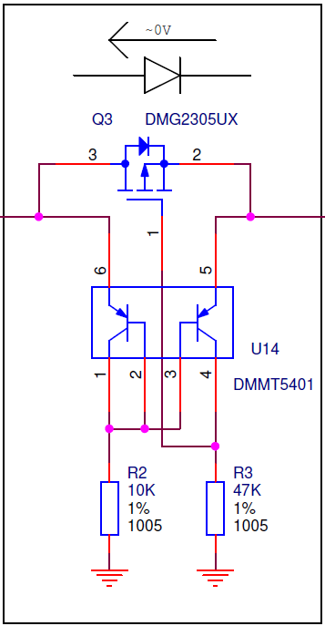
I also wonder if I can use a 0V dropout ideal diode circuit in this scheme. The nice thing about this circuit is it has 0V drop. It is used in raspberry pi, and I got them from their github, referenced below,.

However I dont know if it can be used for this purpose, where the current and back-noise is high.

There is the diode circuit:

(reference: https://github.com/raspberrypi/hats/blob/master/zvd-circuit.png 

Best regards,

C.

  • I would think that Schottky Diodes - larger rated at/around 3A (or higher - as DRV demands) - would prove superior both in terms of "voltage drop/speed of response" and current rating.

    That said - consider the case of the motor driver (either of the two) (near) shorting to ground.     Would not the diode - in series w/your batteries - then pull your batteries to "diode drop" above ground?    (you are aware of the consequences of excessive (and sustained) current draw from (assumed) Lithium Ion batteries - are you not?)

    Are those DRVs spec'ed to perform at such "low-voltage" input?

  • The DRV8801 datasheet says it has Short-to-Supply Protection, Short-to-Ground Protection as well as other protections. Also they will work with min 5V.

    Well, if the drivers short and if the diodes were not there it would pull the batteries to not diode drop above ground but to ground and it would be worst right? Do i need another protection scheme like a polyfuse or a normal fuse?

    What is the expected back-emf from a drv8801? it could of course change by circumstances such as braking, but maybe the drv8801 has some kind of protection? and maybe I should as this with a part number drv8801?

    Best regards,
    C.
  • A few thoughts

    • In this kind of environment you need additional filtering after D2 do deal with noise spikes. Remember that besides blocking the diodes will have an associated parasitic capacitor.
    • In addition overvoltage protection after D1 would be useful in addition to your hold up capacitor.
    • D1 needs to have a high withstand voltage. Not only do you have regen voltage but you have regen current flowing through the motor which is effectively an inductor. you will have a rise in voltage simply because the current will take a finite time to reduce to zero (with the associated reduction in braking torque). This can be reduced by doing limited or no operation in a regen region (ie no braking torque) or adding an overvoltage (braking) circuit to keep the voltage below certain levels.

    I suspect the only real need for D1 is to protect your power source in the event you do not properly control your regen. D2 protects your micro power supply from demands from the motor and the overvoltage protection you should already have after D2 should protect it from regen. This filtering is normally a lot less demanding because it deal with much smaller currents than motors. Your battery should act as a buffer to keep the regen voltage in check (increasing you runtime as a side benefit) but as cb1 pointed out you do need to watch you peak currents.

    The finite speed at which that circuit will turn the FET off

    1. The FET + integral body diode will likely have a higher parasitic capacitance than the diode alone.

    BTW there's seldom a need to use a switching supply to drive a motor.

    Robert

    You could use a more forgiving chemistry for initial testing

  • Thank You Robert,

    This has been helpful. I guess I will have to go to my breadboard, and measure things with my scope.

    I am not planning to use a switching supply to drive the motor, but directly from battery, after the diode.

    How can i do overvoltage protection after D1? And what kind of filtering is needed to deal with noise spikes after D2.

    Best Regards,
    Can
  • In addition to the protections suggested - most Battery Powered Designs we've done (Cordless Power Tools most recently) employ a quick acting, "Current Limiting Function" as well as "temperature limiting" (sensed at the batteries) which proves especially VITAL when Lithium batteries are in play ... and is not covered by your motor driver.     Further note that while you list "DRV protection" - should the DRV fail or become distressed - should that DRV protection ALONE be relied upon?     (under those conditions - is it not likely that "protection" has, "Left the building?"

    While it is tempting to purchase "discount" Lithium Batteries - there are four major (more proper) Lithium Battery Vendors - NONE offering their product at appealing discount!

  • Hello,

    Yes I am totally aware of that. I previously used a fast acting fuse in my previous design, but then purchased some polyfuses and tested them, and I have found out that they are slow and impose a resistance upon the current path. The problem with the quick fuse was that it was soldered, and once it blew up, had to be replaced by soldering iron. With this design I am thinking of using a classical wire fuse, that can be replaced. Basically I have not come to that part of the design.

    Is there anyway to temperature limiting of batteries without using a mcu to measure then to react? Like an analog way?

    While I try to implement best design practices for learning, I am not intending to design a product for sale, but just an open source kit. I understand putting li-ion batteries on a device is liability. And I understand how some battery manufacturers over spec their products, I usually get panasonic. [there is even this brand called "surefire", which are grossly overspecced, so sure, you can expect a fire]

    Thank you,
    C.
  • Fuses prove, "FAR too SLOW" - and their "forced replacement" is both costly and unpleasant.     Both can be avoided - thru MCU monitoring or simple analog circuit measures.   (BOTH current limiting and temperature monitoring/limiting can be achieved via MCU or "analog only" methods.)

    In the simplest terms - you monitor battery current (usually converted to a voltage) and via a properly chosen/placed temperature sensor (which may provide analog or digital output) and when a pre-assigned "trip-point" is exceeded - you, Kill the Supply's Output!      Circuitry to accomplish this should employ "noise resistance" yet act fast to "Reduce or even Break" Power to the downstream (power demanding) circuit.

    MCUs now include analog voltage comparators - which trip far faster than their internal ADCs - and may satisfy your protection requirements.     (conventional analog comparators may also serve such role)    The "beauty" of such method is that, "Neither Damage nor Replacement" is incurred!     (the output power is removed until "w/in range (acceptable)" conditions return.)

    Not for you now - but an industry standard is, "Cycle by Cycle" current limiting - in which an over-current "Kills that particular PWM Cycle" - and in the most fortunate of circumstance - this (may) clear the issue - and the next Cycle may then, "Launch as Normal!     Should the "fault" persist - the output remains "muted."

    The Lithium Battery vendor you "usually get" is one "approved" by giants - who have the resources to make proper qualification.

  • ok, crystal clear. the reason why i emphasized mcu control, is that, the mcu or the software could fault. so i would probably use an analog way.
    best regards.
    -C.
  • Should that eventuality (MCU/SW fault) the "Absence of a regularly occuring MCU signal" proves sufficient to, "Shut Down!"
    Note that certain (several) "Approval Agencies" enjoy "disabling the MCU" during their testing - the "LOS" (loss of signal) method (above) avoids product's rejection...

  • ok, LOS method is mcu calculating something and outputting a signal, and if the signal is not there the device will shut down, right?
    Thanks again,
    -C.
  • It may be a calculation - usually a "Cyclic MCU/Sensors Health Check" and if/when passed - a unique output pulse (which is required) prevents the output stage from "Shutting Down."
  • can altineller said:
    Is there anyway to temperature limiting of batteries without using a mcu to measure then to react?

    Raychem makes devices that do just that.

    Fuses do that generically, but PTC 'fuses' have a more dramatic response to lower temperature variation than 3AG fuses. So the device Raychem manufacture react not only to current but the temperature of the pack. These are designed to be mounted within the pack to keep good thermal contact with the cells.

    I have not used them but they may be worth the check, although as you point out they do have a higher resistance (and lower interrupt rating) than standard fuses.

    Robert

  • can altineller said:
    ok, LOS method is mcu calculating something and outputting a signal, and if the signal is not there the device will shut down, right?

    This can be quite simple, from as simple as the cycle by cycle presented by cb1 (if you feed this into a micro interrupt as well it allows the SW to respond avoiding sitting at the limit).

    A slightly more sophisticated but still simple (only a few logic gates) is to have the HW limit but latch until you receive a clear pulse from the micro (something like a high clears the latch and disables the output, a low enables the output but enables the latch). This ensures that the micro must be operating to recognize the overcurrent signal and respond appropriately to it. If it is not operating then the output remains latched off even if the PWM peripheral operates while the micro does not.

    Robert

  • Hello,

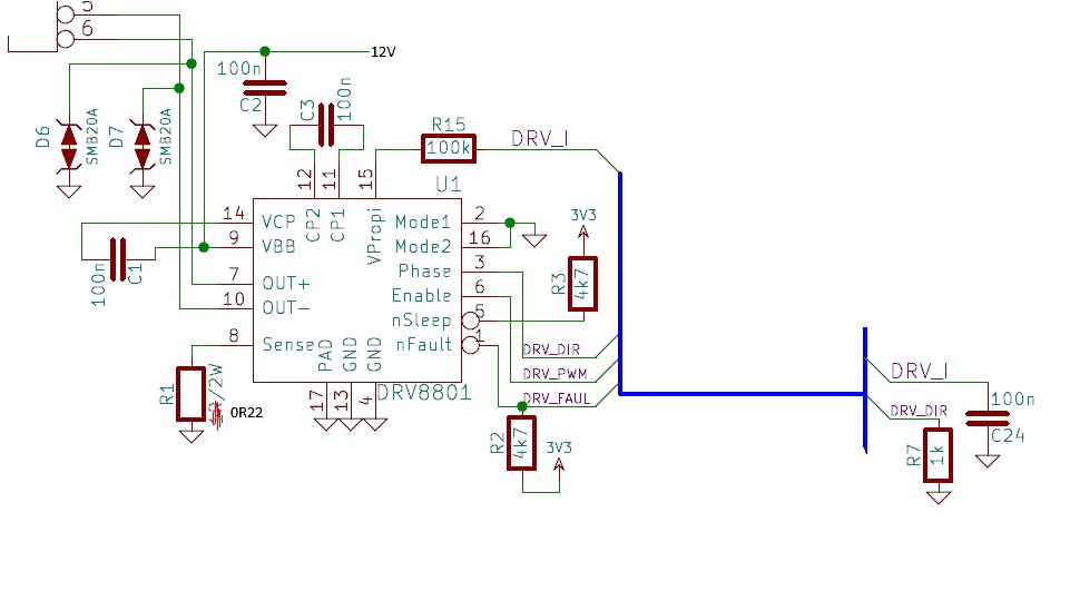
    While I was searching for DRV8801 related images I stumbled upon this schematic.

    The motor outputs are connected to those SMB20A transient voltage suppressors, that break over a certain voltage.

    Would that constitute good way of over-voltage limiting? so the back-emf from the motor may never exceed smb20's breakdown voltage which is like 20V?

    This is particularly important because if I can voltage-limit that line, then I would not have to use de-rated capacitors. I usually use a 63V cap, and it gets big and bulky.

    Best regards,

    C.

  • can altineller said:
    motor outputs are connected to those SMB20A transient voltage suppressors, that break over a certain voltage.    Would that constitute good way of over-voltage limiting?

    Will your motors "always" be limited to such "low voltages?"    (20V as you indicated)     And - do those "devices" attack quickly enough - and w/sufficient accuracy - to protect sensitive circuitry?    

    Such "usual" use of "63V caps" may indicate "re-think" - indeed such devices - when that voltage level is not needed - extract (both) Size & Cost penalties!

    What type of motors are you targeting - and "how" did you arrive @ DRV as "best drive" choice?

  • can altineller said:
    Would that constitute good way of over-voltage limiting? so the back-emf from the motor may never exceed smb20's breakdown voltage which is like 20V?

    That depends on how big the motor is. The worst case scenario is that one of the transorbs has to absorb the entire braking energy (all of the energy in the rotating motor and attached mass) plus any overdriving. That can be a lot of energy.

    can altineller said:
    This is particularly important because if I can voltage-limit that line, then I would not have to use de-rated capacitors. I usually use a 63V cap, and it gets big and bulky.

    You do have a modest battery and since all your acceleration energy came from that it's highly likely it can absorb it and limit the voltage in the process. Since you are running a lithium chemistry you do have to watch cell balancing but it would still be the first thing I'd look at for absorbing the braking energy.

    Robert

  • Hello,

    I am targeting N20 motors with encoders, rated at 6-12V, and I will be driving them with 8.4V. Here is a picture below.

    It would be also nice to work with a bit bigger motors, such as 25Dia pololu motors like in: www.pololu.com/category/115/25d-mm-metal-gearmotors 

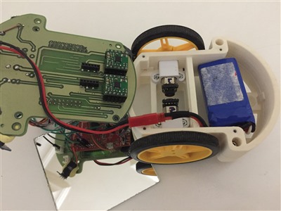
    The DRV8801 was choosen because of small size, low cost, and the fact that it has current sensing. I have built this before using the tiva-c launchpad, a custom board, and pololu drv modules. Here is a picture of it:

    That green board has the Tiva-C on the back, and motor drivers are actually mounted upside down, and there are those black connectors that pop on the pins coming from encoders. So everything is close range.

    So this robot works, but has got some power problems, it will reset the tiva-c under certain circumstances. (and it uses a pololu module for power) - Now I want to redesign this robot board in a more generic way, maybe with little bigger motors, and I really need to get my power circuitry right this time.

    Thank you.

    -C,.

  • Hello Robert, 

    "Since you are running a lithium chemistry you do have to watch cell balancing but it would still be the first thing I'd look at for absorbing the braking energy."

    Do you mean a cell balancer would adsorb the energy and charge the battery in a good way, or the cell balancer would constitute a problem for operation. I was actually planning no using a 2 cell 18650 setup with a 8 shaped battery balancer such as: 

    Best Regards,

    C.

  • Those motors look heavily geared, probably not much regen to worry about, the friction losses will act as an effective brake, unless they are driving a really heavy load.

    can altineller said:
    So this robot works, but has got some power problems, it will reset the tiva-c under certain circumstances. (and it uses a pololu module for power) - Now I want to redesign this robot board in a more generic way, maybe with little bigger motors, and I really need to get my power circuitry right this time.

    I wouldn't use D1 at all in this circuit (especially a small signal diode like a 4004). D2 and the holdup capacitor should protect against momentary transient* dips. While I wouldn't be surprised if that was the major cause there are three others you need to be concerned about given the proximity of the to the motor and power section

    You need to be careful of the layout between the logic and the power sections, they should be well separated and particular attention should be paid to the ground. Indeed, I would suggest using silicon isolators (faster and less current draw than optos) so that the two section do not share the same ground.

    Those small motors are often quite noisy, noise from the motors and from the power section can inductively and capacitively couple to the logic section. You must have significant local filtering, decoupling and bulk capacitance in your logic section. Also a good ground and power plane (I.e. at least one layer each for power and ground), a four layer board minimum.

    While fast edges on the power switching makes for more efficient power sections it also increases the EMI. You may have to trade of efficiency for stability and that's without considering FCC issues.

    Robert

    * Brought to you by the Department of Redundancy Section

  • can altineller said:

    "Since you are running a lithium chemistry you do have to watch cell balancing but it would still be the first thing I'd look at for absorbing the braking energy."

    Do you mean a cell balancer would adsorb the energy and charge the battery in a good way, or the cell balancer would constitute a problem for operation.

    I mean you have to ensure that the cells don't get imbalanced to the point of undercharge and especially not to the point of overcharge. Seeing your motors I doubt your round trip efficiency is high enough to cause much problem but it would be good if your battery management system provided an interlock to shut off regen in the even a single cell was approaching overvoltage if there is any significant regen possible.

    Note the point you reach overvoltage is not only dependent on the state of charge but also the rate of charge.

    Robert