


Part Number: RM48L952
Other Parts Discussed in Thread: HALCOGEN
Hi,
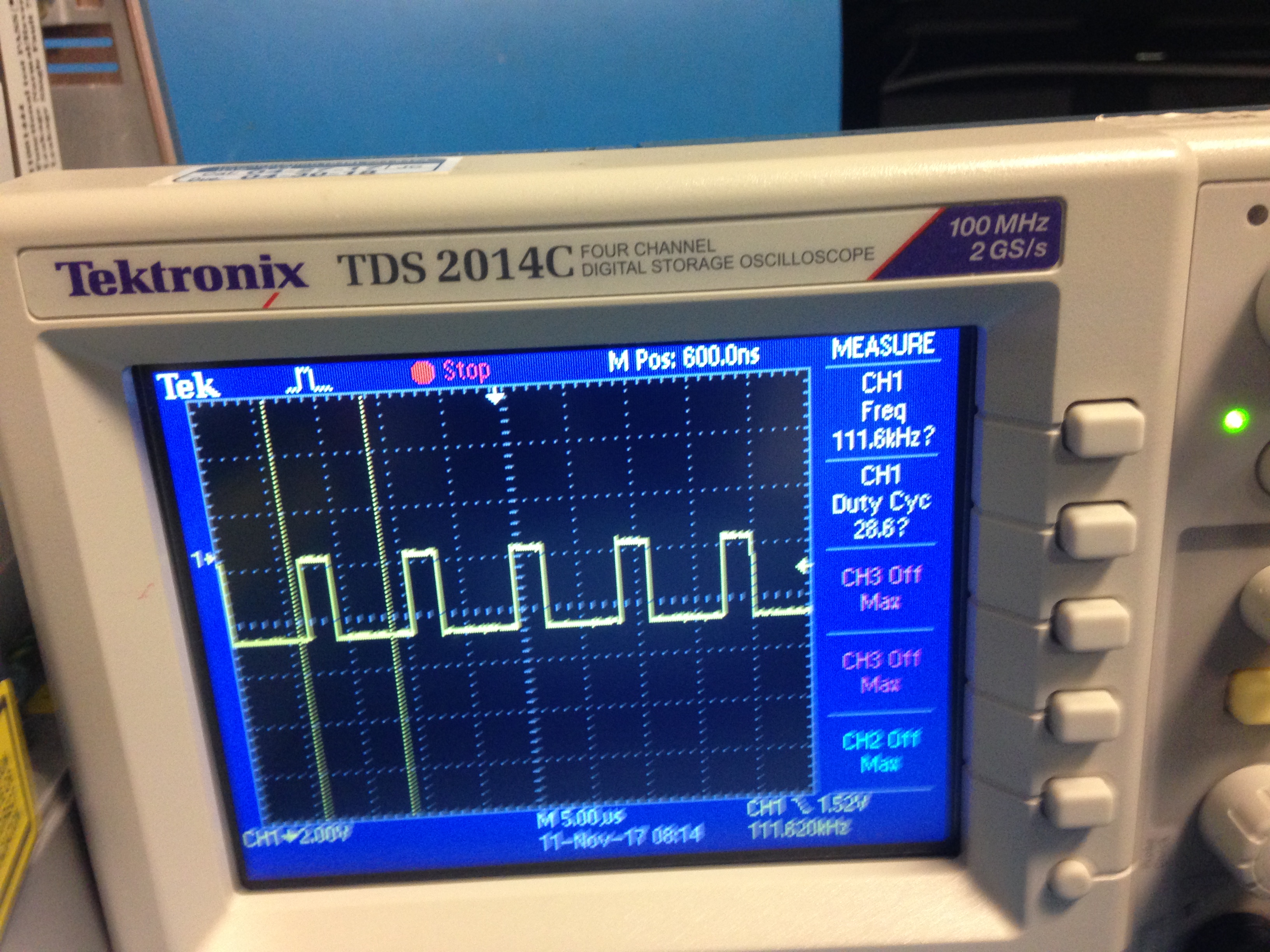
We are using your RM48L952zwt platform with the HalCoGen 4.03.00 generated drivers and based on a sample function we got from TI a few years ago. Our hardware teeam dicovered that the waveform does not match the transmitted settings. i.e., screen shot pwm duty cycle = 37 and freq = 100, the waveform generated has a duty cycle of 28.6
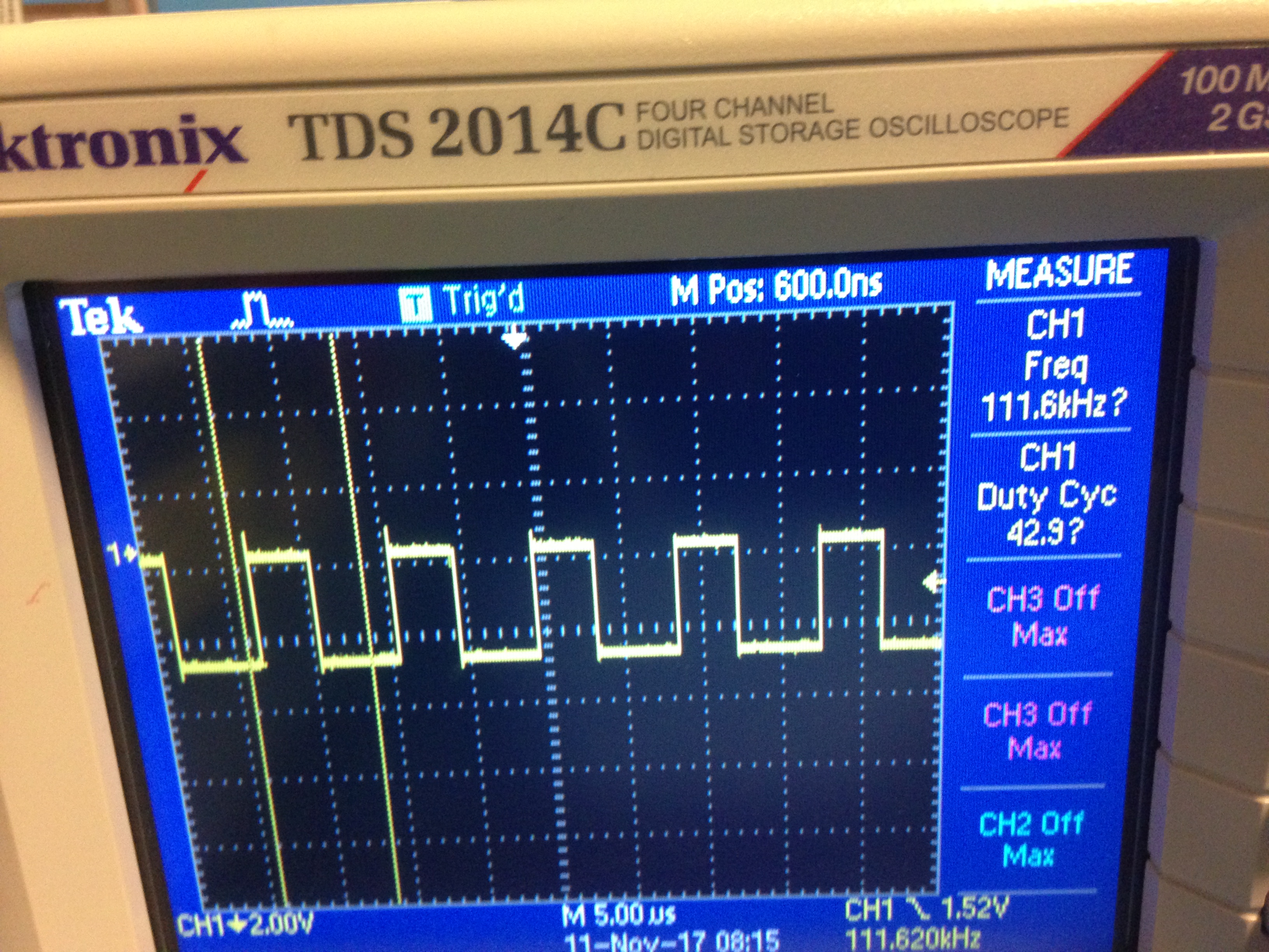
or if pwm duty cycle set to 38 - 40 and freq to 100, the waveform has a duty cycle of 42.9:
/**
* void setPWMOutput(PWM_CHANNEL_TYPE pwm, CPU_INT32U hertz , CPU_FP32 percentage)
*
* @brief sets pwm value for specific channel
*
* @param[in] pwm pwm channel
* @param[in] hertz frequency to use
* @param[in] percentage floating point value
*
* @return void
*/
void setPWMOutput(PWM_CHANNEL_TYPE pwm, CPU_INT32U hertz , CPU_FP32 percentage)
{
CPU_FP64 period = 0;
CPU_FP32 dutyCycle = 0;
CPU_FP32 polarityReversedDutyCycle = 0;
HW_PWM_CONTROL_SET_FN setFn = 0;
//duty cycle can not be more than 100%
if( percentage > MAX_DUTY_CYCLE_PERCENTAGE_VALUE)
percentage = MAX_DUTY_CYCLE_PERCENTAGE_VALUE;
period = (1/((CPU_FP64)hertz)) * 1000 * 1000;
dutyCycle = percentage;
//TODO clean up magic numbers
if(g_pwmPinPolarity[pwm] == POLARITY_ACTIVE_LOW)
polarityReversedDutyCycle = 100 - dutyCycle;
else
polarityReversedDutyCycle = dutyCycle;
if(pwm < PWM_LAST)
setFn = g_pwmPinSetFn[pwm];
if(setFn != 0)
{
//can not set pwm straight to 0, must first set it to an intermediate value then 0
if(polarityReversedDutyCycle == 0)
{
if(g_pwmPinPolarity[pwm] == POLARITY_ACTIVE_LOW)
(*setFn)(g_pwmPinMapping[pwm], period, (100.0 - ONE_PERCENT_DUTY_CYCLE));
else
(*setFn)(g_pwmPinMapping[pwm], period, ONE_PERCENT_DUTY_CYCLE);
OSTimeDlyHMSM(0, 0, 0, PWM_TIME_DELAY);
}
(*setFn)(g_pwmPinMapping[pwm], period, polarityReversedDutyCycle);
dataStruct_setPWMFrequency(pwm, hertz);
dataStruct_setPWMDutyCycle(pwm, percentage);
}
}
Thank you.
