Part Number: TM4C129ENCPDT
We have a custom board using 2MB Everspin MRAM MR4A16B (54-TSOP2 package) on EPI HB16 https://www.everspin.com/family/mr4a16b
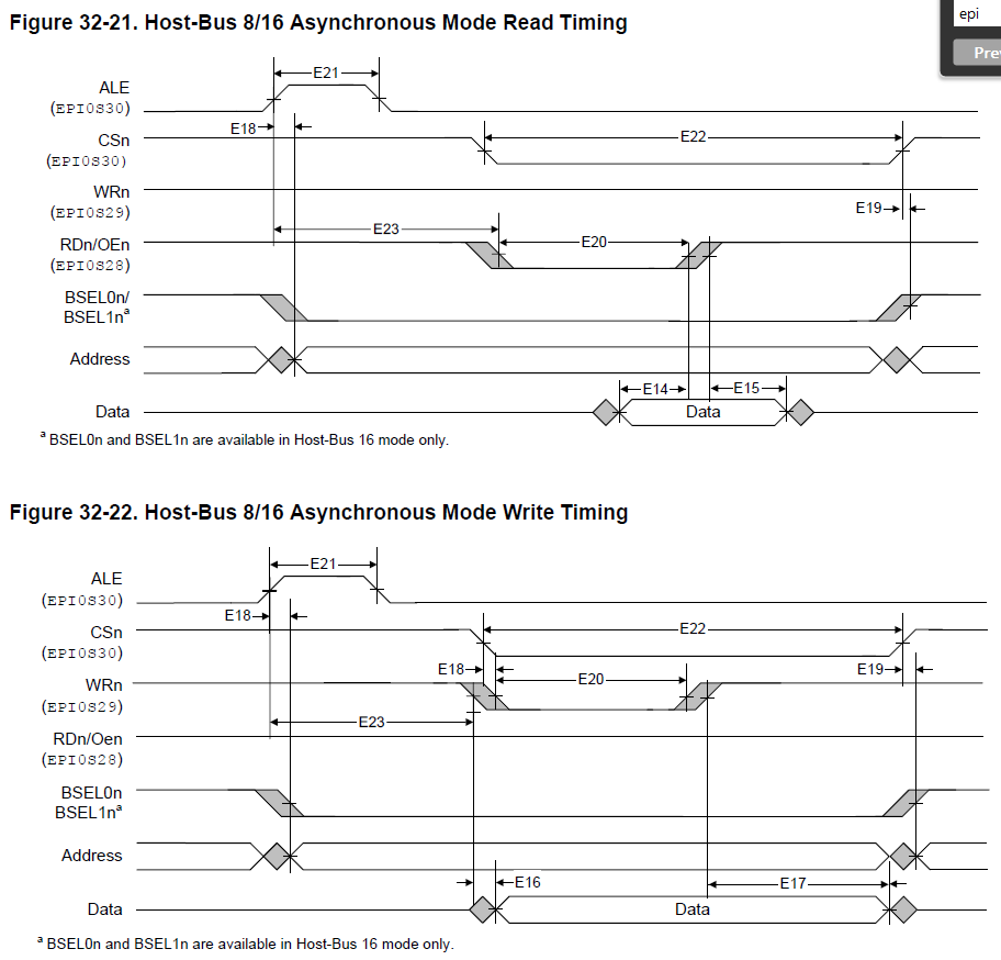
We using Host Bus 16 with multiplexed address and data.
However, we have been having difficulty reading and writing reliably to the MRAM.
Writing issues:
In my test code, I write the same data (0xFFFF) to the whole memory. When I read it back, some of addresses have zero (0x0000) stored in them. I have verified this using the Code Composer Studio memory browser. Somehow, if I immediately read the MRAM back after each word write, the issue does not happen. Still, it would be much better to resolve root cause of this issue.
I found during testing that repeatedly writing 0xFFFF to a word at addresss 0x60XXX4XX (e.g. 0x600E0412) sometimes causes stored data at another address 0x60XXX0XX (e.g. 0x600E0012) to invert (e.g. 0xFFFF -> 0x0000; 0xA5A5 -> 0x5A5A)
Reading issues:
Repeated reads or write-then-reads of the same address sometimes result in erroneous 0x0000 reads.
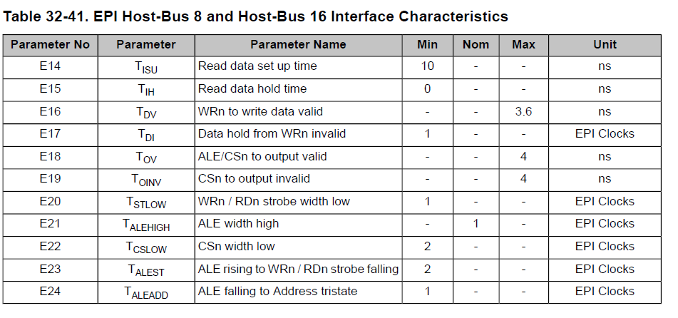
Reducing the Inter-transfer Capture Width (delay between Host-Bus transfers) from the default of 2 EPI clocks to 1 EPI clock eliminates the problem with repeated reads, but does not fix the write-then-read issue.
EPIConfigHB16TimingSet(EPI0_BASE, 0, EPI_HB16_CAP_WIDTH_1);
I’m not sure why this helps.
Here is the EPI initialisation code we are using:
#define EPI_PORTA_PINS (GPIO_PIN_7 | GPIO_PIN_6)
#define EPI_PORTB_PINS (GPIO_PIN_2 | GPIO_PIN_3)
#define EPI_PORTC_PINS (GPIO_PIN_7 | GPIO_PIN_6 | GPIO_PIN_5 | GPIO_PIN_4)
#define EPI_PORTG_PINS (GPIO_PIN_1 | GPIO_PIN_0)
#define EPI_PORTH_PINS (GPIO_PIN_3 | GPIO_PIN_2 | GPIO_PIN_1 | GPIO_PIN_0)
#define EPI_PORTL_PINS (GPIO_PIN_3 | GPIO_PIN_2 | GPIO_PIN_1 | GPIO_PIN_0)
#define EPI_PORTM_PINS (GPIO_PIN_3 | GPIO_PIN_2 | GPIO_PIN_1 | GPIO_PIN_0)
#define EPI_PORTP_PINS (GPIO_PIN_3 | GPIO_PIN_2)


void InitMemory(){
    //Ports used for EPI0
    SysCtlPeripheralEnable(SYSCTL_PERIPH_GPIOA);
    SysCtlPeripheralEnable(SYSCTL_PERIPH_GPIOB);
    SysCtlPeripheralEnable(SYSCTL_PERIPH_GPIOC);
    SysCtlPeripheralEnable(SYSCTL_PERIPH_GPIOG);
    SysCtlPeripheralEnable(SYSCTL_PERIPH_GPIOH);
    SysCtlPeripheralEnable(SYSCTL_PERIPH_GPIOL);
    SysCtlPeripheralEnable(SYSCTL_PERIPH_GPIOM);
    SysCtlPeripheralEnable(SYSCTL_PERIPH_GPIOP);

    //
    // The EPI0 peripheral must be enabled for use.
    //
    SysCtlPeripheralEnable(SYSCTL_PERIPH_EPI0);
    while(!SysCtlPeripheralReady(SYSCTL_PERIPH_EPI0))   //wait for it to be ready
    {
    }

    //
    // This step configures the internal pin muxes to set the EPI pins for use
    // with EPI.

    // EPI0S4 ~ EPI0S7: C4 ~ 7
    GPIOPinConfigure(GPIO_PC4_EPI0S7);
    GPIOPinConfigure(GPIO_PC5_EPI0S6);
    GPIOPinConfigure(GPIO_PC6_EPI0S5);
    GPIOPinConfigure(GPIO_PC7_EPI0S4);
    GPIODirModeSet(GPIO_PORTC_BASE, EPI_PORTC_PINS, GPIO_DIR_MODE_HW);

    // EPI0S8 ~ EPI0S9: A6 ~ 7
    GPIOPinConfigure(GPIO_PA6_EPI0S8);
    GPIOPinConfigure(GPIO_PA7_EPI0S9);
    GPIODirModeSet(GPIO_PORTA_BASE, EPI_PORTA_PINS, GPIO_DIR_MODE_HW);

    // EPI0S10 ~ EPI0S11: G0 ~ 1
    GPIOPinConfigure(GPIO_PG0_EPI0S11);
    GPIOPinConfigure(GPIO_PG1_EPI0S10);
    GPIODirModeSet(GPIO_PORTG_BASE, EPI_PORTG_PINS, GPIO_DIR_MODE_HW);

    // EPI0S12 ~ EPI0S15: M0 ~ 3
    GPIOPinConfigure(GPIO_PM0_EPI0S15);
    GPIOPinConfigure(GPIO_PM1_EPI0S14);
    GPIOPinConfigure(GPIO_PM2_EPI0S13);
    GPIOPinConfigure(GPIO_PM3_EPI0S12);
    GPIODirModeSet(GPIO_PORTM_BASE, EPI_PORTM_PINS, GPIO_DIR_MODE_HW);

    // EPI0S16 ~ EPI0S19: L0 ~ 3
    GPIOPinConfigure(GPIO_PL0_EPI0S16);
    GPIOPinConfigure(GPIO_PL1_EPI0S17);
    GPIOPinConfigure(GPIO_PL2_EPI0S18);
    GPIOPinConfigure(GPIO_PL3_EPI0S19);
    GPIODirModeSet(GPIO_PORTL_BASE, EPI_PORTL_PINS, GPIO_DIR_MODE_HW);

    // EPI0S28 : B2 ~ B3
    GPIOPinConfigure(GPIO_PB2_EPI0S27);
    GPIOPinConfigure(GPIO_PB3_EPI0S28);
    GPIODirModeSet(GPIO_PORTB_BASE, EPI_PORTB_PINS, GPIO_DIR_MODE_HW);


    // EPI0S29 ~ EPI0S30: P2 , 3
    GPIOPinConfigure(GPIO_PP2_EPI0S29);
    GPIOPinConfigure(GPIO_PP3_EPI0S30);
    GPIODirModeSet(GPIO_PORTP_BASE, EPI_PORTP_PINS, GPIO_DIR_MODE_HW);

    // EPI0S00 ~ EPI0S03 : H0 ~ H3
    GPIOPinConfigure(GPIO_PH0_EPI0S0);
    GPIOPinConfigure(GPIO_PH1_EPI0S1);
    GPIOPinConfigure(GPIO_PH2_EPI0S2);
    GPIOPinConfigure(GPIO_PH3_EPI0S3);
    GPIODirModeSet(GPIO_PORTH_BASE, EPI_PORTH_PINS, GPIO_DIR_MODE_HW);

    GPIOPadConfigSet(GPIO_PORTA_BASE, EPI_PORTA_PINS, GPIO_STRENGTH_8MA, GPIO_PIN_TYPE_STD);
    GPIOPadConfigSet(GPIO_PORTB_BASE, EPI_PORTB_PINS, GPIO_STRENGTH_8MA, GPIO_PIN_TYPE_STD);
    GPIOPadConfigSet(GPIO_PORTC_BASE, EPI_PORTC_PINS, GPIO_STRENGTH_8MA, GPIO_PIN_TYPE_STD);
    GPIOPadConfigSet(GPIO_PORTG_BASE, EPI_PORTG_PINS, GPIO_STRENGTH_8MA, GPIO_PIN_TYPE_STD);
    GPIOPadConfigSet(GPIO_PORTH_BASE, EPI_PORTH_PINS, GPIO_STRENGTH_8MA, GPIO_PIN_TYPE_STD);
    GPIOPadConfigSet(GPIO_PORTL_BASE, EPI_PORTL_PINS, GPIO_STRENGTH_8MA, GPIO_PIN_TYPE_STD);
    GPIOPadConfigSet(GPIO_PORTM_BASE, EPI_PORTM_PINS, GPIO_STRENGTH_8MA, GPIO_PIN_TYPE_STD);
    GPIOPadConfigSet(GPIO_PORTP_BASE, EPI_PORTP_PINS, GPIO_STRENGTH_8MA, GPIO_PIN_TYPE_STD);

    // Configure the GPIO pins for EPI mode.
    // This step also gives control of pins to the EPI module.
    GPIOPinTypeEPI(GPIO_PORTA_BASE, EPI_PORTA_PINS);
    GPIOPinTypeEPI(GPIO_PORTB_BASE, EPI_PORTB_PINS);
    GPIOPinTypeEPI(GPIO_PORTC_BASE, EPI_PORTC_PINS);
    GPIOPinTypeEPI(GPIO_PORTG_BASE, EPI_PORTG_PINS);
    GPIOPinTypeEPI(GPIO_PORTH_BASE, EPI_PORTH_PINS);
    GPIOPinTypeEPI(GPIO_PORTL_BASE, EPI_PORTL_PINS);
    GPIOPinTypeEPI(GPIO_PORTM_BASE, EPI_PORTM_PINS);
    GPIOPinTypeEPI(GPIO_PORTP_BASE, EPI_PORTP_PINS);

    // Now that we have configured GPIO pins, configure the EPI module.
    // 120MHz CPU, set EPI clock to 120/8 = 15MHz
    // Minimum read/write cycle time = 35ns == 28MHz
    EPIDividerSet(EPI0_BASE, 6); // EPI clock is 1/8th of CPU

    EPIModeSet(EPI0_BASE, EPI_MODE_HB16);
    EPIConfigHB16Set(EPI0_BASE,
                    (EPI_HB16_CSCFG_ALE_SINGLE_CS | //sets EPIS030 to operate as an address latch (ALE) and EPIS027 is used as a chip select.
                     EPI_HB16_MODE_ADMUX |//Address and Data are multiplexed
                     EPI_HB16_ALE_HIGH //Address latch enable is active high
                    ),
                     0);

//    EPIConfigHB16TimingSet(EPI0_BASE, 0, EPI_HB16_CAP_WIDTH_1);

    // Set the address map.
    // MRAM is only 2MB, choose nearest larger option.
    EPIAddressMapSet(EPI0_BASE, EPI_ADDR_RAM_SIZE_16MB | EPI_ADDR_RAM_BASE_6);
}
Here is the function we use to test the memory writing:
void TestMemory(){

    uint16_t pattern = 0xFFFF; // the data we write to each word
    const uint32_t numBytes = 0x200000; // 2MB
    const uint32_t numWords = numBytes /sizeof(uint16_t); // 16 bit words
    volatile uint16_t* ramBaseAddress = (volatile uint16_t*) 0x60000000;
    int index;
    while(1){
        for (index = 0; index < numWords; index++){
            //First write the pattern to each word
            ramBaseAddress[index] = pattern;


            // Somehow, immediately reading the memory
            // back after each write avoids the issue.

            // uint16_t readBack = *ramBaseAddress;
            // uint16_t readBack = ramBaseAddress[index];
        }

        for (index = 0; index < numWords; index++){
            // Check that data in each word matches the pattern
            if (ramBaseAddress[index] != pattern){
                System_printf("Error @0x%x: Expected: 0x%x, Got: 0x%x\n", &ramBaseAddress[index], pattern, ramBaseAddress[index]);
                System_flush();
            }
        }
    }
}
Here's the main function for completeness
int main(void)
{
    InitMemory();

    TestMemory();

    return (0);
}
Here is the console output of the function on one of the boards
Error @0x60180004: Expected: 0xffff, Got: 0x0
Error @0x60180404: Expected: 0xffff, Got: 0x0
Error @0x60100002: Expected: 0xffff, Got: 0x0
Error @0x60100402: Expected: 0xffff, Got: 0x0
Error @0x60040228: Expected: 0xffff, Got: 0x0
Error @0x60040628: Expected: 0xffff, Got: 0x0
Error @0x601c0108: Expected: 0xffff, Got: 0x0
Error @0x601c0508: Expected: 0xffff, Got: 0x0
Error @0x60020018: Expected: 0xffff, Got: 0x0
Error @0x60020418: Expected: 0xffff, Got: 0x0
Error @0x600a0028: Expected: 0xffff, Got: 0x0
Error @0x600a0428: Expected: 0xffff, Got: 0x0
Error @0x60000048: Expected: 0xffff, Got: 0x0
Error @0x60000448: Expected: 0xffff, Got: 0x0
Error @0x60060108: Expected: 0xffff, Got: 0x0
Error @0x60060508: Expected: 0xffff, Got: 0x0
Here is the console output of the function on another board
Error @0x60020004: Expected: 0xffff, Got: 0x0
Error @0x60020804: Expected: 0xffff, Got: 0x0
Error @0x601a1004: Expected: 0xffff, Got: 0x0
Error @0x601a1804: Expected: 0xffff, Got: 0x0
Error @0x60141004: Expected: 0xffff, Got: 0x0
Error @0x60141804: Expected: 0xffff, Got: 0x0
Error @0x601e0004: Expected: 0xffff, Got: 0x0
Error @0x601e0804: Expected: 0xffff, Got: 0x0
Error @0x601c1004: Expected: 0xffff, Got: 0x0
Error @0x601c1804: Expected: 0xffff, Got: 0x0
I have attached a zip of my project (which uses TI-RTOS for console output).
I would be grateful if a contributor can help shed some light on my memory issues.