This thread has been locked.

If you have a related question, please click the "Ask a related question" button in the top right corner. The newly created question will be automatically linked to this question.

CCS/EK-TM4C129EXL: Error connecting to the target

Part Number: EK-TM4C129EXL
Other Parts Discussed in Thread: SEGGER, EK-TM4C1294XL, UNIFLASH

Tool/software: Code Composer Studio

Hi everybody,

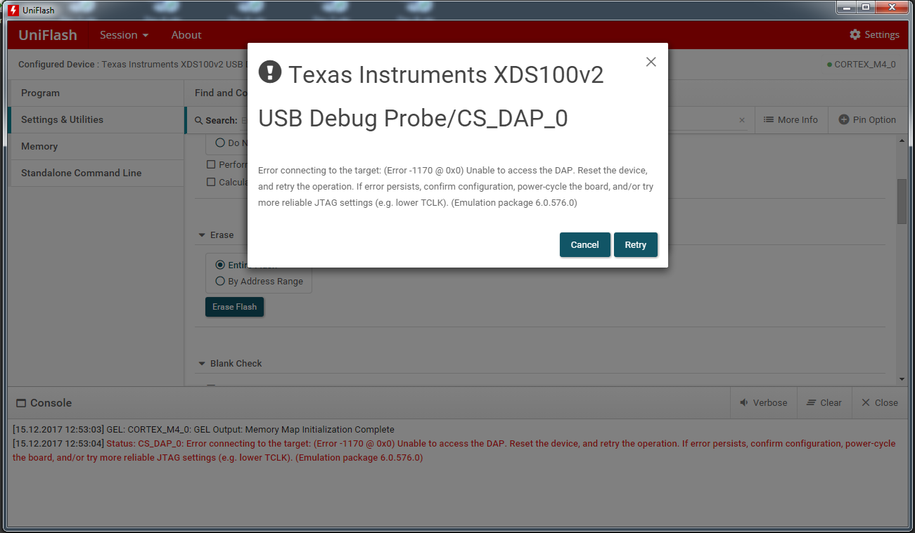
I have the EK-TM4C129EXL Launchpad (I use the on board Stellaris debug Interface) and I downloaded my own software on it, which, among others has a USB Host Interface implemented. I was doing tests and debugging the software with CCS and everything was doing fine. At some point, I connected the USB to test the communication and wanted to debug. Since then the CCS Shows: "Error connecting to the target", when the Firmware has to be downloaded on the chip. Since then, I cannot debug anymore, but the software on the MCU is running...

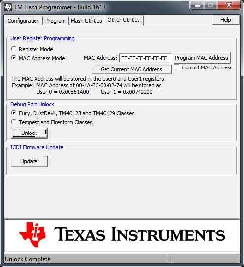
I tried to erase the flash with the LM Flash Programmer but I get the error   "**ERROR**: Unable to initialize target -0!"

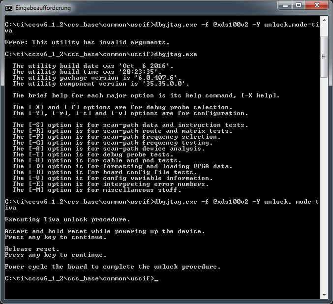
Then I unlocked the MCU using the LM Flash Programmer Debug Port Unlock Utility. The process was finished successfully.

I still get the error with the LM Flash programmer when I want to erase the Flash or with the CCS when I want to load my program.

Hence, I have a software running on my MCU, but I cannot download a Firmware anymore.

Do you have any idea what the Problem could be??

Thanks a lot in advance!!

Greetings,

Sara

  • Hi Sara,
    How did you know that the unlock was successful? Are you saying that after the unlock the firmware is still in the flash? If this is the case then the unlock did not succeed. Please try again. If the unlock is successful then the flash should be completely erased. In the LM flash programmer under the Other Utilities you can click on the Get Current MAC Address. What does it return? If unlock is successful it will also erase your LaunchPad MAC address. It should show FF-FF-FF-FF-FF-FF.

    Try below steps.

    1. Unpower the board and press reset

    2. Power the board but do not release the reset

    3. Run the unlock sequence according to the LM programmer "dialog box"

    4. Power Cycle the board

    5. Do a Flash Erase Check or load a simple program to confirm the debugger can access the MCU again
  • Sara Fernandez said:
    At some point, I connected the USB to test the communication and wanted to debug. Since then the CCS Shows: "Error connecting to the target"

    So, so many end up here  in "just" your situation.      (yet vendor "finds the time to KILL LIKE - and AVOID this KNOWN/ON-GOING ISSUE!)

    You do not describe, "How you connected the USB to test" - there are more than 1 USB port on your board - which did you use?"

    Feel your pain (yet we avoid your MCU) and it is hoped that vendor will "Deal w/REAL ISSUES" - rather than "Wasting time/effort - on (very) poorly conceived "forum down-grades!"

    The "Recovery Process is "quite detailed" you must follow vendor Charles' instructions - exactly.    (especially the (admittedly) cumbersome "hold of Reset.")

    If you're "with a firm" perhaps one there has a "real/proper JTAG/SWD probe (J-Link)" -  that probe proves "surprisingly EFFECTIVE" in recovering such "DEAD MCUs!"

  • Hi Charles,

    the LM Flash Programmer just gave the message the unlock has been successful, but the flash still has the firmware and the MAC Address is also there (I also get the error when I try to read the MAC with the LM Flash Programmer, but the firmware I flashed it reads it out). I tried several times this unlock process (just as you described), but always with the same result.

    Thank you for your help,
    Sara
  • Hi,

    there are 2 USB: one 1 use for debugging and the other one I use for communication with the MCU as Device so it appears as VCOM in the PC.

    I dont really understand how J-Link JTAG could help me on this...
  • The J-Link Probe was introduced long before vendor "attempts" - is notably more complete/complex - and firm/I have (on multiple occasions) restored "your class" MCUs to operation - via its utilization!     (this is a "real J-Link" - running Segger's comprehensive software - outside of  "vendor limitations..."

    There (must) be a reason for its, "World's Top Selling/Delivered JTAG/SWD Probe" - might that be true?

    What do you - and literally "hundreds before you," share in common in such JTAG lockout?"      (that's a worthwhile search path - is it not?)

  • Hi Sara,


    1. Can you refer to the section 5.3 on this app note www.ti.com/.../spma075.pdf and try again on the unlock sequence. It is important that you first hold the reset button (don't release it) while you are powering up the device.


    2. Can you take the screenshot of the LM Flash Programmer under the "Other Utilities" tab after the unlock sequence.?


    3. If this is still not successful, do you have another known good Launchpad that you can try with the unlock sequence. I want to know you had a board problem.


    4. Do you have other jtag debug probe (Jlink, XDS or others) that you can externally connect to the TM4C1294 Launchpad? If you have one, please try it to see if you can connect and then from the IDE (i.e. CCS) try to erase the flash.


    5. If you have XDS debug probe (XDS100v2, XDS200) you can use the utility dbgjtag.exe to unlock the device. Please follow the app note I reference.
  • Hi cb1_mobile,

    unfortunately I dont have a J-Link JTAG to test it out :(

  • Hi Charles,

    1. I dont release the reset button when power it on, and follow the instruction comming from the LM Flash Programmer. Here a screenshot after releasing reset:

    2. I power cycle the board and the process is successfully finished

    .

    3. A new EK-TM4C1294XL is on the way. When it gets here, I try it and inform you.

    4. I have a XDS100v2 and already tried with CSS and Uniflash to erase the flash or to download a new firmware. I get with both also an error. Here an screenshot of the error showed by Uniflash:

    5. I used the dbgjtag.exe to unlock the board:

    I still cannot unlock the board...

    Thanks a lot for your help,

    Sara

  • Hi Sara,

     Sorry to hear that the device is still not yet recovered. Not sure what the root cause is. From the screenshot the MAC address is all F's. So it seems the unlock was successful but you still cannot connect to the target. If the unlock was truly successful then it means the jtag was ok because the unlock sequence needs to manipulate the jtag interface to scan in unlock patterns. Was the MAC address already F's before you had any problem with the board. if the MAC address changed from non-F's to all F's then the unlock was successful.

     While you are waiting for the new board can you check:

     1. On the problem board if the VDD and VDDA supply rails are 3.3 V. Also check with a digital multi-meter that the VDDC rail is 1.2 V.

     2. Since you have XDS100, you can run a scan test in CCS. See below.

     Let's know your result with the new board arriving.

  • Hi Charles,

    the F's showing in the MAC address form the LM Flash Programmer are the default values from the software, it is not the "real" current value because as soon as I press "Get current MAC address" I get the error I sent you in the screenshots.

    I checked what you sugested:
    1. 3.3V in VDD and VDDA and also 1.2V in VDDC are correct.

    2. I run the scan test with the following output:

    [Start: Texas Instruments XDS100v2 USB Debug Probe_0]

    Execute the command:

    %ccs_base%/common/uscif/dbgjtag -f %boarddatafile% -rv -o -F inform,logfile=yes -S pathlength -S integrity

    [Result]


    -----[Print the board config pathname(s)]------------------------------------

    C:\Users\user\AppData\Local\TEXASI~1\CCS\
    ti\0\0\BrdDat\testBoard.dat

    -----[Print the reset-command software log-file]-----------------------------

    This utility has selected a 100- or 510-class product.
    This utility will load the adapter 'jioserdesusb.dll'.
    The library build date was 'Jul 21 2017'.
    The library build time was '19:36:41'.
    The library package version is '7.0.48.0'.
    The library component version is '35.35.0.0'.
    The controller does not use a programmable FPGA.
    The controller has a version number of '4' (0x00000004).
    The controller has an insertion length of '0' (0x00000000).
    This utility will attempt to reset the controller.
    This utility has successfully reset the controller.

    -----[Print the reset-command hardware log-file]-----------------------------

    The scan-path will be reset by toggling the JTAG TRST signal.
    The controller is the FTDI FT2232 with USB interface.
    The link from controller to target is direct (without cable).
    The software is configured for FTDI FT2232 features.
    The controller cannot monitor the value on the EMU[0] pin.
    The controller cannot monitor the value on the EMU[1] pin.
    The controller cannot control the timing on output pins.
    The controller cannot control the timing on input pins.
    The scan-path link-delay has been set to exactly '0' (0x0000).

    -----[The log-file for the JTAG TCLK output generated from the PLL]----------

    There is no hardware for programming the JTAG TCLK frequency.

    -----[Measure the source and frequency of the final JTAG TCLKR input]--------

    There is no hardware for measuring the JTAG TCLK frequency.

    -----[Perform the standard path-length test on the JTAG IR and DR]-----------

    This path-length test uses blocks of 64 32-bit words.

    The test for the JTAG IR instruction path-length failed.
    The JTAG IR instruction scan-path is stuck-at-zero.

    The test for the JTAG DR bypass path-length failed.
    The JTAG DR bypass scan-path is stuck-at-zero.

    -----[Perform the Integrity scan-test on the JTAG IR]------------------------

    This test will use blocks of 64 32-bit words.
    This test will be applied just once.

    Do a test using 0xFFFFFFFF.
    Test 1 Word 0: scanned out 0xFFFFFFFF and scanned in 0x00000000.
    Test 1 Word 1: scanned out 0xFFFFFFFF and scanned in 0x00000000.
    Test 1 Word 2: scanned out 0xFFFFFFFF and scanned in 0x00000000.
    Test 1 Word 3: scanned out 0xFFFFFFFF and scanned in 0x00000000.
    Test 1 Word 4: scanned out 0xFFFFFFFF and scanned in 0x00000000.
    Test 1 Word 5: scanned out 0xFFFFFFFF and scanned in 0x00000000.
    Test 1 Word 6: scanned out 0xFFFFFFFF and scanned in 0x00000000.
    Test 1 Word 7: scanned out 0xFFFFFFFF and scanned in 0x00000000.
    The details of the first 8 errors have been provided.
    The utility will now report only the count of failed tests.
    Scan tests: 1, skipped: 0, failed: 1
    Do a test using 0x00000000.
    Scan tests: 2, skipped: 0, failed: 1
    Do a test using 0xFE03E0E2.
    Scan tests: 3, skipped: 0, failed: 2
    Do a test using 0x01FC1F1D.
    Scan tests: 4, skipped: 0, failed: 3
    Do a test using 0x5533CCAA.
    Scan tests: 5, skipped: 0, failed: 4
    Do a test using 0xAACC3355.
    Scan tests: 6, skipped: 0, failed: 5
    Some of the values were corrupted - 83.3 percent.

    The JTAG IR Integrity scan-test has failed.

    -----[Perform the Integrity scan-test on the JTAG DR]------------------------

    This test will use blocks of 64 32-bit words.
    This test will be applied just once.

    Do a test using 0xFFFFFFFF.
    Test 1 Word 0: scanned out 0xFFFFFFFF and scanned in 0x00000000.
    Test 1 Word 1: scanned out 0xFFFFFFFF and scanned in 0x00000000.
    Test 1 Word 2: scanned out 0xFFFFFFFF and scanned in 0x00000000.
    Test 1 Word 3: scanned out 0xFFFFFFFF and scanned in 0x00000000.
    Test 1 Word 4: scanned out 0xFFFFFFFF and scanned in 0x00000000.
    Test 1 Word 5: scanned out 0xFFFFFFFF and scanned in 0x00000000.
    Test 1 Word 6: scanned out 0xFFFFFFFF and scanned in 0x00000000.
    Test 1 Word 7: scanned out 0xFFFFFFFF and scanned in 0x00000000.
    The details of the first 8 errors have been provided.
    The utility will now report only the count of failed tests.
    Scan tests: 1, skipped: 0, failed: 1
    Do a test using 0x00000000.
    Scan tests: 2, skipped: 0, failed: 1
    Do a test using 0xFE03E0E2.
    Scan tests: 3, skipped: 0, failed: 2
    Do a test using 0x01FC1F1D.
    Scan tests: 4, skipped: 0, failed: 3
    Do a test using 0x5533CCAA.
    Scan tests: 5, skipped: 0, failed: 4
    Do a test using 0xAACC3355.
    Scan tests: 6, skipped: 0, failed: 5
    Some of the values were corrupted - 83.3 percent.

    The JTAG DR Integrity scan-test has failed.

    [End: Texas Instruments XDS100v2 USB Debug Probe_0]

    so, the scan is not successfully.

    On the meantime the new board arrived. On it everything is working fine: I can unlock it and reprogramm it and also all the tests I run in the no-functional board are running on the new one.

    Is it possible that some of the JTAG pins from the maincontroller got corrupted or are broken?? If that is the case, do you might know why and how? I wouldnt like it to happen again in the new board or any of our products going to the market with this microcontroller.

    Thanks a lot for your help!
    Sara
  • Hi Sara,

     Can you take scope capture of the JTAG interface. Below is what I capture (TCK, TMS, TDI, TDO) when running the connection test. What do you see on the TDO?

  • HI Sara,
    Also examine the board and look for any obvious damage on the Debug USB port. Look inside the micro-A connector and see if anything is bent. Can you swap the USB cable that connects to the bad board (I got this idea from the other post answered by cb1). With a new USB cable, do you see any difference. Please capture the JTAG interface and compare with the new board.
  • There are numerous potential "causes" of such difficulty.      Unknown is the existence of any "external connections" between poster's failed board and the "outside world."      While the MCU manual "suggests" that, "providing input signals to the unpowered (or incompletely powered) MCU" - appears to be acceptable (under some conditions) my firm much prefers, "Prevention of such signal arrivals - when the MCU is unpowered."     This strategy places "signal & power discipline" above, "hope & prayer."     (Not that there's anything too wrong w/ "hope/prayer" - other than their "minimalization @ the finest engineering schools.)

    Our firm takes the additional safeguard of employing small value series resistors upon each JTAG/SWD line.      And - as long noted here - use of external pull-up Rs - an order of magnitude lower in value than the MCU's (free) internal Rs - which is proven to produce more robust signalling while providing (some) input protection.

    ESD is a "convenient" catch-all when problems arise.      As semiconductor geometries shrink - ESD's potential for mayhem increases.       One must employ, "Proper ESD management - throughout each/every step in the component arrival/unpacking - auto placement & reflow - and "finished board" Test/Verify."       Note that "not always" will ESD damage reveal its presence - immediately!     In user's case - damage may have occurred anywhere - even repeatedly - along the unpack/place/reflow/test chain.      Often the ESD destruction "grows & extends" - (while not "yet" being noted) which complicates the discovery of  the "critical, earlier, ESD (time & place) arrivals!"      (which in time - doomed user's board...)

    Also unknown is the "Destructive Potential" of the programming/debug tools - which are "minus the "substantial history & long-term success" of better known - and far more capable & extensive such tools. The fact that these newer/less capable vendor tools (appear) to work -in no way removes them from, "Prime Suspect" or from, "Aiding & Abetting" (i.e. being complicit in) the "Lock-Out issues" - unfortunately reported - with great & ongoing regularity - right here...  

    This explains why several here have suggested use of, "Better known & more capable programming/debug tools" - which have a far longer & rich history - and have the power conferred by being "vendor agnostic" - indicating their superior depth, development and reach...      Removing one of the "potential sources" of such (dreaded) Lock-Out IS KISS compliant - and provides (some) positive movement - (i.e. the apparent (only) movement) towards issue resolution...

  • Hi Charles,
    sorry for the late answer, Christmas Holidays... :)
    the USB connector seems OK to me and changing the cable doesnt change anything.
    Regarding TDO signal, for me is always low in the non-working board (I got the clock on TCK and TDI is also sending data, but TDO is not even at high level). On the new board is everything working fine: the signals are like you posted...
    Could be possible, like posted, that the TDO pin due to ESD is not functional anymore?

    Thanks a lot for all your support,
    Sara
  • Greetings Ms Fernandez,

    Kindly note that friend Charles is (likely) "wading thru what's left of the Florida Keys" - during his "well earned" vacation.
    He's most dedicated, skilled & interested - but any/all response (may most likely) be delayed.

    I must note that you remain "silent" as to the "interconnection" of your failed board - AT ANY TIME - IN ANY WAY - to the "outside world!" Minus so significant info - we "lesser skilled/equipped" helpers - are less likely to offer up "meaningful" diagnosis...