This thread has been locked.

If you have a related question, please click the "Ask a related question" button in the top right corner. The newly created question will be automatically linked to this question.

Compiler: PWM DEADTİME CONFİGURATİON !!!

Other Parts Discussed in Thread: LMG5200

Tool/software: TI C/C++ Compiler

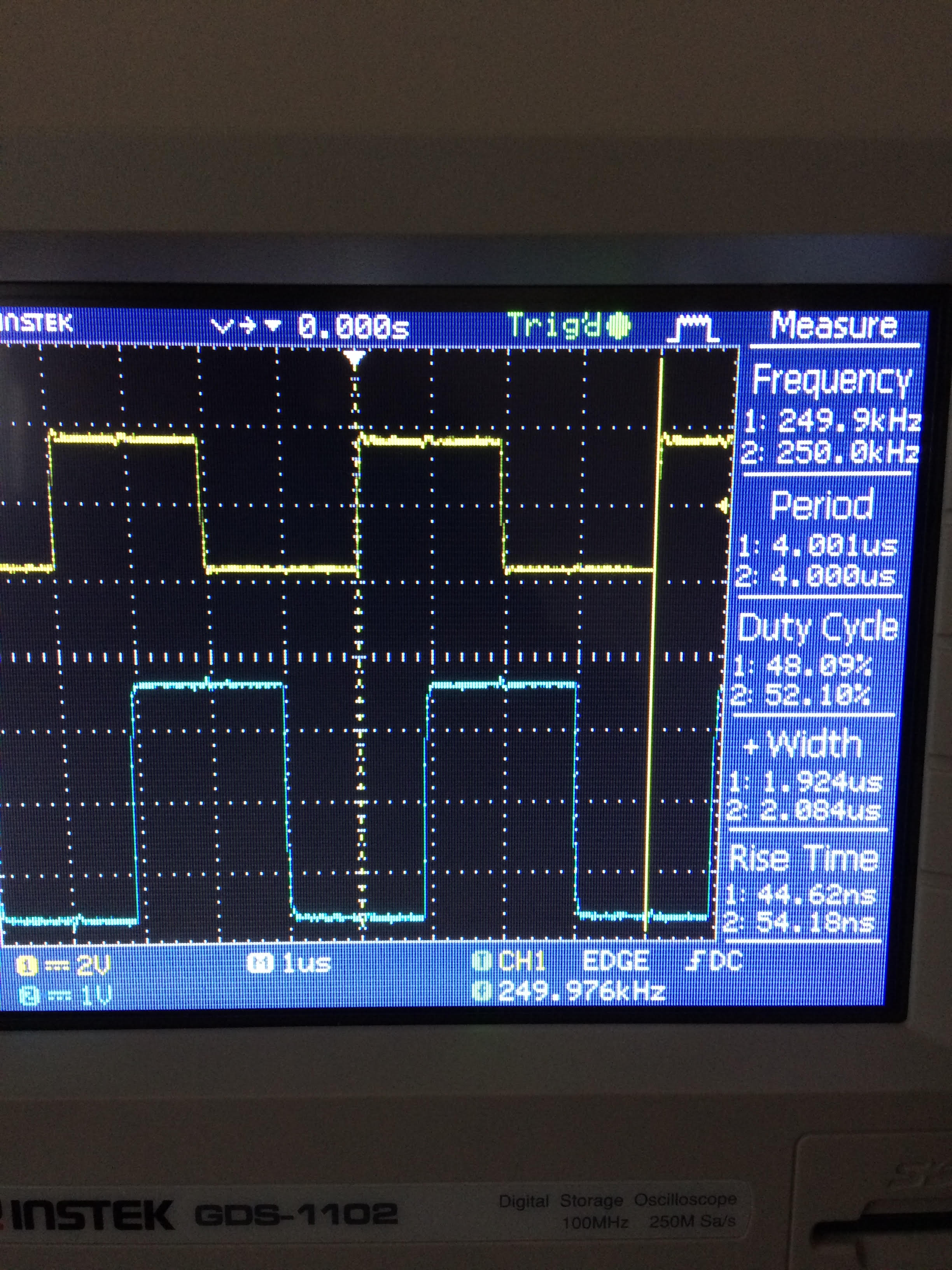
How can I produce a deadtime that will be 20 percent of the pwm period ?

where do i make mistakes ?

#include <stdint.h>
#include <stdbool.h>
#include "inc/hw_memmap.h"
#include "inc/hw_types.h"
#include "driverlib/sysctl.h"
#include "driverlib/gpio.h"
#include "driverlib/debug.h"
#include "driverlib/pwm.h"
#include "driverlib/pin_map.h"
#include "inc/hw_gpio.h"
#include "driverlib/rom.h"


int main(void)
{

uint32_t cycle;
uint32_t pwmfrequency;
uint32_t deadband;
uint32_t pwmperiod;
pwmperiod=50;
pwmfrequency=SysCtlPWMClockGet()/pwmperiod;
deadband=pwmperiod*20/100;
cycle=pwmperiod*50/100;

SysCtlClockSet(SYSCTL_SYSDIV_1|SYSCTL_USE_PLL|SYSCTL_OSC_MAIN|SYSCTL_XTAL_16MHZ);
SysCtlPWMClockSet(SYSCTL_SYSDIV_8);
SysCtlPeripheralEnable(SYSCTL_PERIPH_PWM0);
SysCtlPeripheralEnable(SYSCTL_PERIPH_PWM1);
SysCtlPeripheralEnable(SYSCTL_PERIPH_GPIOE);
SysCtlPeripheralEnable(SYSCTL_PERIPH_GPIOD);

GPIOPinTypePWM(GPIO_PORTE_BASE,GPIO_PIN_4);
GPIOPinTypePWM(GPIO_PORTE_BASE,GPIO_PIN_5);

GPIOPinTypePWM(GPIO_PORTD_BASE,GPIO_PIN_0);
GPIOPinTypePWM(GPIO_PORTD_BASE,GPIO_PIN_1);


GPIOPinConfigure(GPIO_PE4_M0PWM4);
GPIOPinConfigure(GPIO_PE5_M0PWM5);

GPIOPinConfigure(GPIO_PD0_M1PWM0);
GPIOPinConfigure(GPIO_PD1_M1PWM1);

PWMGenConfigure(PWM0_BASE,PWM_GEN_2,PWM_GEN_MODE_UP_DOWN|PWM_GEN_MODE_NO_SYNC);
PWMGenConfigure(PWM1_BASE,PWM_GEN_0,PWM_GEN_MODE_UP_DOWN|PWM_GEN_MODE_NO_SYNC);

PWMGenPeriodSet(PWM0_BASE, PWM_GEN_2,pwmperiod);
PWMGenPeriodSet(PWM1_BASE, PWM_GEN_0,pwmperiod);


PWMDeadBandEnable(PWM0_BASE,PWM_GEN_2,deadband,0); // pd1


//PWMDeadBandEnable(PWM1_BASE,PWM_GEN_0,deadband,0); // pe4


PWMOutputState(PWM0_BASE, PWM_OUT_4_BIT,true);
PWMOutputState(PWM0_BASE, PWM_OUT_5_BIT,false);


PWMOutputState(PWM1_BASE, PWM_OUT_0_BIT,false);
PWMOutputState(PWM1_BASE, PWM_OUT_1_BIT,true);

PWMGenEnable(PWM0_BASE, PWM_GEN_2);
PWMGenEnable(PWM1_BASE, PWM_GEN_0);


while(1)
{


PWMOutputInvert(PWM0_BASE,PWM_OUT_4_BIT,true);
PWMPulseWidthSet(PWM0_BASE, PWM_OUT_4,cycle);
// PWMPulseWidthSet(PWM0_BASE,PWM_OUT_5,cycle);

//PWMPulseWidthSet(PWM1_BASE,PWM_OUT_0,cycle);
PWMPulseWidthSet(PWM1_BASE,PWM_OUT_1,cycle);

}
}

  • Have you seen the example code in TivaWare:
    C:\ti\TivaWare_C_Series-2.1.4.178\examples\peripherals\pwm\dead_band.c
  • Note too that there "ARE LIMITS" upon the amount of "dead-time" which may be imposed.       (the API's PDL exposes those limits - enforced by the "dead-time" function.)

    It (may) prove possible to "roll your own function" - to "defeat" (at least extend those limits) - you assume all risk if you elect that method.        (see my "Providers of Content" boilerplate - at the base of each forum page...)

  • In addition to others great input might add it is not always necessary or required to enable dead band generators depending on the type & method of inverter synchronization.

    The 249-250Khz PWM frequency would play nicely with TI GaN drivers and gain huge efficiency. There are several short online training seminar, search GaN drivers.

  • What "others''" great input?        One & only one post  identified the "gotcha" which lurks "unrevealed"  w/in "deadband.c!"

    void

    PWMDeadBandEnable(uint32_t ui32Base, uint32_t ui32Gen,

                     uint16_t ui16Rise, uint16_t ui16Fall)

    {

       //

       // Check the arguments.

       //

       ASSERT((ui32Base == PWM0_BASE) || (ui32Base == PWM1_BASE));

       ASSERT(_PWMGenValid(ui32Gen));

       ASSERT(ui16Rise < 4096);   //   thus 4096/65535 = 6.25%  ...  suggests  "maximum dead-band as % of pulse width"   (does not consider the "fold-back" nature of "dead-band")

       ASSERT(ui16Fall < 4096);

    Depending upon poster's PWM Frequency - the unusual magnitude of his (desired) deadband - may not enable such a setting!     (without skillful & repeated, "machete use" ...  to "hack the example code..."

  • And even bigger issue may exist in the PWMCLK  being 2Mhz even capable to produce any desired machete hack of example project.

    Besides poster requires 20% of said PWM period = DB, is such an edge time even possible (2000000 / 250000 = 8 ticks) or (500ns / 4us = 125ms) tick period. The 16Mhz CPU clock / 8 = 2Mhz PWMCLK, seems a bit slow for producing such a high PWM frequency and adding 200-300ns (typical) DB time into each PWM period. Code below assumes (deadband)=125*20=2500 and (cycle)=125ms*50=6250. Yet the decimal point (0.125) is missing in my example, factoring by posters actual tick periods we get 2.5 and 6.25 relatively. Perhaps move PWMCLK decimal point, increase tick period a relative factor of 10, move it 6 places to the left gives 60Mhz PWMCLK, that even seems a bit slow in my gut if poster desires 249-250kHz (fixed) PWM frequency. What is posters desired min/max Ton/Toff periods, we have to assume an inverter with dead band in the mix and does the PWM duty cycle change relative to actual inverter load. 

    Who knows what the posters desired PWM frequency even is, that has not been clarified other than poster providing a signal capture of what exactly!

    pwmperiod=50;
    pwmfrequency=SysCtlPWMClockGet()/pwmperiod;
     deadband=pwmperiod*20/100;
     cycle=pwmperiod*50/100; 
    
     SysCtlClockSet(SYSCTL_SYSDIV_1|SYSCTL_USE_PLL|SYSCTL_OSC_MAIN|SYSCTL_XTAL_16MHZ);
    SysCtlPWMClockSet(SYSCTL_SYSDIV_8); 

  • Note that the "catch-all" example - while being quick/easy - shows not, "Overt attention to detail" - sometimes (perhaps even often) required!
    Such remains the "value" of the "non-machine-gunned, outsider" helper crüe...
  • Note you were spot on (2.5%/6.25%) agrees with an actual PWM math equation. Do you have any advise to poster as what might be a minimum PWMCLK needed to achieve (assume 250kHz PWM frequency) prior to adding dead time into a PWM period.

    Is there not a factor or multiplier recommended in the TM4C129x datasheet as to what the PWMCLK must be relative to the smallest desired PWM period. Perhaps other TI forums datasheets go into great detail in this area. TI seminar video training could be more relative in the long run at very high PWM frequency. Past Tivaware DB example was not written for TM4C129x processor and required many tweaks just to get it running.

    OBTW; example proved little to no help in real world application enabling DB generators in certain type inverters.

    https://training.ti.com/how-get-started-gan-power-design-under-3-minutes

  • As we've (long) since moved to M0 (for cost sensitive designs) and M7 (for higher performing ones) my advice (remains) as stated.
    Always & only - vendor agents remain "uncritical" in challenging "such strange/unusual" poster requests - which "tacitly" - if not directly - encourages such.

    Why is 20% dead time required - what IS its magic?      Why is it left  - "always/only"  - to questing outsiders - to request such ... and for such efforts - our "Reward of LIKE" is cast off!     (for the most suspect & tortured of reasons!)

  • sorry, I do not fully understand the meaning,I am using microcontroller for the first time.
    Would you be a little more descriptive? How can I solve the problem?
  • Your desire for 20% Dead Band proves unusual - it is a very high value for dead-band.
    The frequency of your PWM signal - especially should it be (relatively) low - may yield "excessive dead-band time periods!"

    Why do you believe you require a 20% dead-band?     From where did that idea originate?

    The purpose of dead-band is to attempt to minimize any (near) simultaneous conduction of (both) your (likely) High and Low Side Power Devices (FETs usually) - a condition called "Shoot-Through" - which usually (if not quickly & forcefully limited) results in the destruction of  your Power Stage!      (and too - your pcb - should you be especially unlucky)

    Your taking the time/effort yourself - to be "little more descriptive" - appears necessary to further resolve your issue.     It is (very) much doubted that a 20% dead-band proves a "proper" (or even realistic) requirement!

  • I understood thank you.
    but the question that is at mind is: for example, can I get two pwm output signals from PB6 and PB7 of port B?
    M0PWM0 will invert .M0PWM0 and M0PWM1 will be delay rising edge .
    Is this possible ?
    thank u cb1_mobile.
  • We try to get emre to outline frequency objectives so helpers can guide in a proper direction. 

    Could it be emre was not being more descriptive of (all) intended goals? This forum is not going to solve your dead band timing issues other than indicate points needing review, think about.

    TI seminar video links (above post) will give you a better idea of how frequency & dead band % can effect inverter efficiency.

    Has emre bothered to review video ? or simply reply no helpers understand his desire to achieve the unachievable.

  • Yes - surely you can - and I will (gladly) guide you.       As a (somewhat) successful "tech biz owner" - my preference is to,  "Teach Methods of Attack" - so that your capabilities & confidence MULTIPLY - my interest thus is (almost) never ... to provide (blindly accepted) "Cut and Paste!"

    it is noted that you "Remain Silent" as to the "necessity" for 20% (and only 20%) Dead-Band prescription.    Are we (now) freed from such concern?     (which I believe to be invalid - and not to your favor!)

    Your learning would be greatly assisted via your locating and read/review of:

    • "MCU Manual" - starting w/first chapter (general description) - then moving to "PWM Peripheral Section"
    • "Peripheral Driver Library User's Guide" - absolutely terrific document - makes your effort SO much faster, easier, coherent!
    • "TivaWare\Examples\Peripherals\PWM -  neat code examples - but read ONLY after your read/review of the 2 (far more detailed) items - above.     Shortcuts do NOT work!   Will cause immense "Pain/Suffering" - (Not to ask - "How I know?")

    If you signal your agreement to, "Launch the Learning Path" just detailed - I'll provide (basic) code - (yet NEVER "all of the code") as you're served best via "Techniques/Methods" - NEVER by (blind) Cut/Paste...

  • It would appear the advice/guidance - moments ago provided - proves, "No longer necessary/desired."   (Issue has been marked, "Resolved.")

    And so clearly - "No such resolution" has (yet) occurred.

    (Fear not ...  cb1 - once more - launches search for a "pistol" ... and  "forum-guidance/caring" - (now ending)  "head shot" - looms large...)

  • And some of the best guidance posted in this forum also deserves a green stamp of approval!!

    To my surprise the GaN seminar (link above) scope captures show DB delay near 1.7ns, WOW. Seems to indicate a highly efficient PWM system possible with GaN. The TI GaN module kit can quickly launch a beginner to understanding how DB delay effects overall inverter efficiency. Besides that forum users can connect kit onto most any launch pad and capture 1/2 bridge DB delay results. Seemingly It is most difficult to capture high frequency DB delay produced by (one) generator without a 1/2 bridge and scope probe connections.

  • BP101 said:
    And some of the best guidance posted in this forum also deserves a green stamp of approval!!

    Are you speaking of the, "vector to example\peripherals posting?"

    BP101 said:
    Seemingly It is most difficult to capture high frequency DB delay produced by (one) generator without a 1/2 bridge and scope probe connections.

    Pardon - but have I not "Done exactly that" (capture "HF" (yet undefined, here) Dead-Band imposed upon one PWM Generator's dual outputs - and (completely) ABSENT any "half-bridge?"     I've posted such - right here - more than once - year or so back...

    Obviously - with 2 channel scope probes connected.   (that point (somehow) escapes me.)

    Read your PM - crack staff has written...

  • Was referring to your steps posted above.
  • Ya think?     Is "gunpowder" dangerous when in such "Low Humidity" conditions?   (it is 2°F now in Chi.)  

    "Kat/Dawg" draw (very) neat ARCS when they contact each other - or (even) moi.

    ESD rules - especially when the "heaters are on & at, (high duty cycle)" - and w/minimal (far from 20%) dead-band!"      (another NEAT Fun FACT!)

    Can you say, "Multiple Loss of JTAG" ... coming up - for those "TM4C users" w/in US midwest and/or north east?

  • GaN video uses a function generator to develop 2.0ns Rise and 1.7ns Fall DB delays, mistaken 12ns.
  • Huh?     (Pardon but "so what?")     Does not poster's issue of   "20% and only 20%" Dead-Band ... (STILL) sit & fester - unresolved? 

    Does not Gan introduction, "cloud/obscure" beginning poster's "quest?"      You do realize that "higher frequency" makes his quest (20% dead-band) (even) harder - do you not?

  • LMG5200 (12ns/1.7ns) DB delay seems to occur inside the GaN driver, perhaps poster discovered DB is built into LMG5200 GaN switch. Honestly I totally missed that the first few times watching video.
  • Really - are we not "flying" Full Speed - into the  so very tall, "Weeds."

    Has poster made (any) mention of LMG5200 - at all?       (if so - I may have to reduce (both) ... access to weaponry & alcohol.)      Or more likely - just (one) of those (required) two...

    Crack Staff Breakfast (on the Great Lake (Michigan) calls) - firepower placed (temporarily)  "on hold."