This thread has been locked.

If you have a related question, please click the "Ask a related question" button in the top right corner. The newly created question will be automatically linked to this question.

CCS/TM4C1290NCPDT: I2C SCL period deviation.

Part Number: TM4C1290NCPDT
Other Parts Discussed in Thread: EK-TM4C1294XL

Tool/software: Code Composer Studio

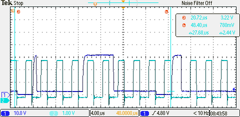
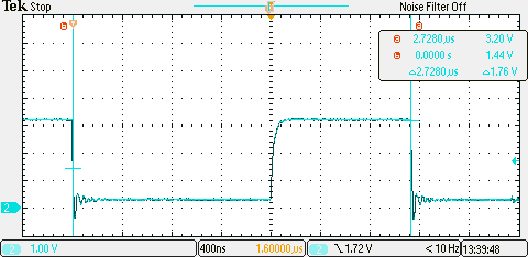
Measuring the I2C clock period, showed a deviation of what was calculated using the formula that was mentioned in the datasheet: SCL_PERIOD = 2 × (1 + TIMER_PRD) × (SCL_LP + SCL_HP) × CLK_PRD

We used the fast mode and a system clock  of 60MHz, the Timer period was set to 7. Calculated was 375kHz, but we measured 365kHz on the scoop.

The calculated multiplication factor was 160. In order to come to a frequency 365kHz, the multiplication factor should have been 164. This is not possible to achieve with the mentioned formula.

Do you have any possible explanation for this deviation?

  • Would not your "issue" prove (even) more compelling if you'd describe, "Why you require such high accuracy?"
    Does your I2C slave (suffer) - at all - from a 10/375 "deviation?"

    Should there be (real) justification for such accuracy - should not your, "Confirmation of your system clock's frequency" prove, "first order of investigation?"    You may employ an MCU Timer to output a proper, (known) 'frequency divided replica" of "system clock" - while avoiding "Any/all disturbance" - to your (assumed) external crystal circuitry...   (almost "guaranteed" to occur - should you "probe" your external xtal.)

  • Hi Jan,
    Did you let the oscilloscope auto calculate the frequency or you hand measure the SCL clock period between two edges?
  • Greetings Charles,

    Following (which may prove of interest) is noted upon poster's scope cap:

    • trigger is not set to the I2C clock channel
    • Channel voltage levels are set FAR differently (10:1 - possibly signaling different/unmatched scope probes)
    • the left edge "measurement cursor" - to my eye - (I approach - yet am not yet, "legally blind") appears Not "coincident" w/a signal edge
    • trigger level set to 4.80V - when such signal (appears) to "reach" to 30V - deserves (some) explanation - does it not?

    Your identification/question is indeed sound - and I'd "far more trust" the "scope's frequency calculation" (over a reasonable sampling period) than any "too small" or (manual) sample collection...

  • Another thing to consider when measuring I2C baud rate is the impact of clock stretching. The I2C master must sample when SCL goes high and recalculate the bit time based on when it reads SCL high, not when it released SCL. Clock stretching by the slave such as before the acknowledge bit, or just the capacitance of the SCL line could cause that 3% difference in baud rate.
  • *** LIKE ***   Excellent - and unrecognized by all before!    

    Still - unexplained is (any) justification for such speed - and am I (alone) in questioning the (apparent) Ch2 signal reaching to 30V (even) bit beyond?

    It may be acceptable to set the trigger to 80-90% (of max) or 10-20% (of min) - but to 4.8V out of 30V - by what means was that derived?

    I continue in the belief that the forum would "be aided" if poster's would be (somewhat) instructed to "Justify - at least explain" their (often suspect) desires...

  • I don't need that accuracy, but I just want to know why it behaves different than what is described  in the spec.

  • Measured the time of 10 clock pulsed and calculated the frequency.

  • Yes, I am sorry that the scope capture showed not the right values, but believe me, I measured several times the clock frequency and each time, I came up with 365kHz.
  • Thanks Bob.

    Although I don't understand the clock stretching precisely, I can image that such a phenomenon, causes additional master clock periods.
    Do you think it is possible that it causes 4 additional master clock periods?
  • Sorry for the incomplete trace, but the issue was related to timing not on voltage levels.
  • My friend - No sorrow sought nor expected.

    It is "curious" that your "Ch_2" (cyan) represents your I2C clock - yet it does NOT serve as "trigger source" for your "SCL" measurement - don't you agree?        Instead, Ch_1 (likely "SDA") was set as trigger - and reveals a 10:1 "voltage or scope probe variation" - which may prove sub-optimal when high accuracy is sought.

    Any "intrusion" of "Slave Clock Stretching" may be best detected by setting your "SCL" scope channel to trigger upon SCL's "active low duration" (perhaps 5-10% greater) than that (normally) "calculated or measured."      (I believe the "Slave" device to "hold SCL low" - until its operation "completes" - and then "release.")      

    IIRC - such "stretch" may vary depending upon the particular Slave, pull-up resistor value, bus-load, AND the specific "operation" imposed upon the Slave...

    You may "challenge & confirm" the MCU's ability to, "match your SCL's frequency expectations" by transmitting to a "Ghost Slave!"    (i.e. No slave)       Such should allow one such I2C transmission before "ACK" fails.      (you may note that some here are "fanatic enough" to devise logic which supplies a, "faked ACK" - yet prove incapable of any/all "clock stretching!")     Shines a (very) bright light upon the MCU's (actual) SCL frequency.      Such "bright light" proves a "powerful antiseptic" to any/all "unwanted, outside MCU, (alleged),  "influences/distortions!"

  • I made another trace, where I triggered at the falling edge of the SCL and measured the time until the next falling edge.

    The time appeared to be 2.73us and very stable over multiple traces.

    So clock stretching is not very likely to be the cause of the deviation.

  • Well - that IS one method - but I doubt as effective as the, "Automated Detection" of an "Extended SCL low state" - which was previously detailed.

    You may note that "one here" - sounded the alert - against  "Excusing the MCU's frequency deviation"  (as you well detected & reported) - casting blame (instead) upon "sinister/outside forces!"

    Automated measurements - as suggested - exist for good reason - and I believe prove "best" (by far) in  "your service..."

  • Jan Stoter said:
    So clock stretching is not very likely to be the cause of the deviation.

    Based on what reasoning?

    Question have you verified that the dive can actually respond at full speed w/o clock stretching? The data sheet should reveal any upper end speed limitations of the device (should, not certain). cb1's suggestion of measuring w/o the influence of the device is a good one.

    There may be an additional possibility. Depending on layout and pull-ups the shape of the waveform may vary between the micro and the device. The device may find it necessary to clock stretch in order to meet its minimum times. The micro and device may be capable to the higher speed but your layout may prevent it. If so kudos to the IIC  implementation to making this work in adverse conditions.

    Robert

  • I really think that it is clock stretching, and stretching caused by the rise time of SCL independent of the slave. I configured an EK-TM4C1294XL launch pad to run at 60MHz and generate a 400KHz I2C clock. The actual TPR value ended up being 7. The calculated SCL period is:

    SCL_PERIOD = 2 * (1 + TPR) * (SCL_Low + SCL_High) * SYS_PERIOD

    SCL_PERIOD = 2 * (1 + 7) * (6 + 4) * (1/60MHz)

    SCL_PERIOD = 160/60MHz = 2.67uS (375 KHz)

    Using a 3.3K Ohm pull up on SCL, I measured the period of SCL with no slave attached as seen in the picture below:

    The measured period was 2.78 uS which correlates to a 360 KHz baud rate (as opposed to a calculated 375 KHz baud rate). This is similar to the results of the original poster.

    Next, I replaced the 3.3K pull up with a 330 Ohm pull up. This is too strong a pull up for real use as the device was not able to pull the signal low, but it did give a very sharp rise time to the SCL signal as shown below:

    With the sharp rise time, I measured the same calculated bit time of 2.66uS.

    My conclusion is that the actual baud rate of I2C will be slower than the calculated baud rate due to the clock stretching caused by the rise time of the SCL line. That rise time is a function of the pull up resistor and the capacitance of the SCL line. A slave device could stretch the clock signal more if needed.

  • That's an interesting & resourceful series of experiments - yet we were taught that, "I2C Clock Stretching" was "normally/customarily" the province of the "Slave Device" - exclusively!  

    Earlier it was mentioned (here) that the pull-up resistor and/or I2C bus loading may impact I2C "clock frequency" but such is not "normally" considered, "I2C Clock Stretching."    

    Philips - the originator of I2C - is the "Controlling legal authority" (thank you Al Gore) for "I2C" - and it is believed that their documentation best defines such, "I2C based, clock stretching" - which proves a, "deliberate mechanism - launched by an I2C Slave - to insure that the Slave has time to  fully/properly  "process & respond" to the "Master's Command !"

  • Hi CB1,
    I agree that it is the intent of clock stretching to be used by the slave device, but how can a master device (even one from Philips) tell the difference from a small delay caused by a slave device and a small delay caused by the RC rise time of the SCL line? The only thing the master device can do is wait for its input buffer to see SCL as high, and then start the timing for the next clock pulse.

    While this has been interesting, and it is best to understand any discrepancies from the behavior we expected, you early on made a really important point. For proper operation it does not matter.
  • Hi Bob,

    I'd respond - as you so often suggest here - that "proper terminology" has its place - and "Clock Stretching" is (and remains) as its inventor dictated...

    It is "expected" that the user will design (again as you've often guided here) with proper component selection & placement - which "minimizes" I2C bus issues - yet accommodates the Slave's (need) to "process & later respond."      It is the "latter" which (really) qualifies as, "clock stretching" - yet we (both) agree - the I2C Master (the TM4C here) little cares...     (and - the interest in such clocking accuracy proves, "more curiosity than (real) value.")

  • Thanks Bob.

    This is what I was looking for. This is a good explanation why the clock frequency is lower than expected. Apparently the master waits until the SCL has been pulled high, before it continues its own clock cycle.

    Thanks for your effort in making this experiment. It has been very useful.

    Best regards, Jan Stoter