This thread has been locked.

If you have a related question, please click the "Ask a related question" button in the top right corner. The newly created question will be automatically linked to this question.

TM4C1294KCPDT: Is this the basic I need to make 1294 stand alone?

Part Number: TM4C1294KCPDT

I need to add stand alone feature to an old logger design using TM4C1294, it needs to keep the RTC running when main power is off, when the main power is back on, it reads the RTC and continue with the task interrupted before the power was removed

Are the following addition enough for the hardware? I just need to add enough so that I can order a prototype to work on the codes

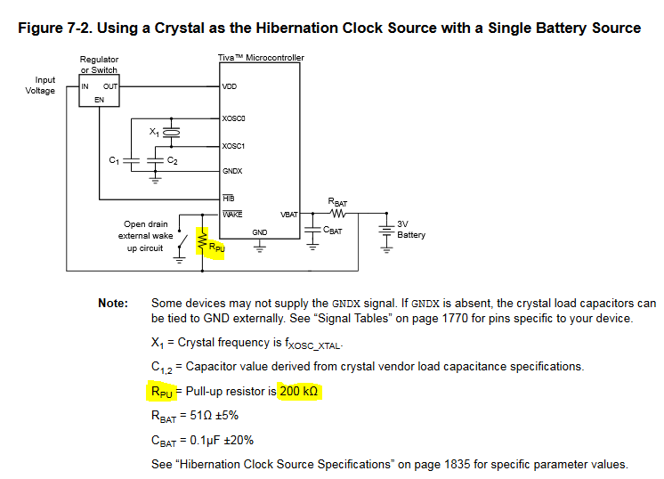
  1. Add a 3V cell battery to VBAT pin of TM4C1294 
  2. Populate the 32.768K crystal and caps for XOSC0 and XOSC1

What do I do with WAVE pin? Connecting to ground only when external power is detected, otherwise connect it to 3V cell battery?

Thanks!

  • The recommendation for the WAKE pin is a 200K pullup to VBAT.

  • May I, "LIKE" - especially the use of  "color"  to "highlight" those critical component values & location...

    Such highlight would save MANY from the Plague-Istors (R9/10) which are well camouflaged - thus all too often - "missed!"     (so simple a fix - never implemented!)

  • is this an official TI reference design? with the battery directly connected to a power source?

    just curious, :)
  • No, the charging circuit for the battery is beyond the scope of the discussion where this diagram is used. I agree, it should not have shown that connection between the raw input voltage and the battery.

  • Kudos to poster Danny for that observant, "catch."

    Would not a, "quick/easy fix" - achievable (even) under a basic "Paint" program -  result by simply "erasing the unwanted connection path between, "Input Voltage" and Rpu?"    (erasing 1 vertical line & "left segment" of the horizontal line.)

    Such drawings - we've found - when "left unfixed" - (especially when "left unfixed") - may exhibit  the "nasty tendency" to develop a, "Life of their own!"        And (may)  "circulate"  -  re-appearing, "widely & repeatedly!"    (Note too - that  "not all"  users  will,  "continue their read"  -  to the bitter (yet battery/design saving)  end!)

    (it IS suspected that you've (simply) "Cut/Pasted" from a (pardon) "Poorly proofed" - Source document" ...  OR ...  that a  "TWO (separate) Input"  Switch - should have been drawn.)     (preventing the "unwanted, direct connection"  from "External Voltage Source to the battery" - which presently  displays...)   

    The benefits from such simple,  "drawing correction" - operate,  "Much in your  (and hapless users') favor!"