Part Number: TM4C129ENCZAD
Hi,
I am trying to setup SSI in quad mode with DMA TX/RX, but am having issues with the interrupt handler. As soon as I call SSIIntEnable(SSI1_BASE, SSI_DMATX), my interrupt handler will endlessly go off.
I have found what seems to be the exact same issue in this other thread:
https://e2e.ti.com/support/microcontrollers/tiva_arm/f/908/t/361916
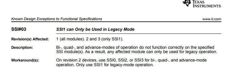
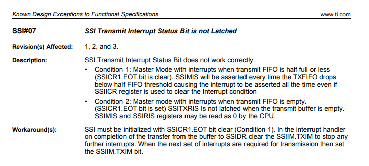
and have tried everything suggested in that thread to the best of my knowledge, and also referred to the errata which said to do this:
Here is my initialization code:
void Board_initQSSI(uint32_t SysClk_Freq, uint32_t baud_rate)
{
    // Enable QSSI Peripherals (using ports B, D, E on QSSI1)
    MAP_SysCtlPeripheralEnable(SYSCTL_PERIPH_SSI1);
    MAP_SysCtlPeripheralEnable(SYSCTL_PERIPH_GPIOB);
    MAP_SysCtlPeripheralEnable(SYSCTL_PERIPH_GPIOD);
    MAP_SysCtlPeripheralEnable(SYSCTL_PERIPH_GPIOE);

    // Pin function via mux setting. This macro is mapped to GPIOPinConfigure in rom_map.h.
    // GPIOPinConfigure is def in gpio.c
    MAP_GPIOPinConfigure(GPIO_PB5_SSI1CLK);
    MAP_GPIOPinConfigure(GPIO_PB4_SSI1FSS);
    MAP_GPIOPinConfigure(GPIO_PE4_SSI1XDAT0);
    MAP_GPIOPinConfigure(GPIO_PE5_SSI1XDAT1);
    MAP_GPIOPinConfigure(GPIO_PD4_SSI1XDAT2);
    MAP_GPIOPinConfigure(GPIO_PD5_SSI1XDAT3);

    // Pin operation settings. This macro is mapped to GPIOPinTypeSSI in rom_map.h.
    // GPIOPinTypeSSI is def in gpio.c
    MAP_GPIOPinTypeSSI(GPIO_PORTB_AHB_BASE, GPIO_PIN_4 | GPIO_PIN_5);
    MAP_GPIOPinTypeSSI(GPIO_PORTD_AHB_BASE, GPIO_PIN_4 | GPIO_PIN_5);
    MAP_GPIOPinTypeSSI(GPIO_PORTE_AHB_BASE, GPIO_PIN_4 | GPIO_PIN_5);

    // Disable QSSI
    MAP_SSIDisable(SSI1_BASE);

    // Set to SPI Mode0 for QSSI (Advanced) mode; set master mode
    MAP_SSIConfigSetExpClk(SSI1_BASE, SysClk_Freq, SSI_FRF_MOTO_MODE_0, SSI_MODE_MASTER, baud_rate, 8);

    // Enable advanced mode
    MAP_SSIAdvModeSet(SSI1_BASE, SSI_ADV_MODE_QUAD_READ);

    // Fill the TX buffer with a dummy data pattern
    g_ui8TxBuf[0] = 0xAB;

    // Enable the uDMA controller at the system level.
    MAP_SysCtlPeripheralEnable(SYSCTL_PERIPH_UDMA);

    // Enable the uDMA controller.
    MAP_uDMAEnable();

    // Point at the control table to use for channel control structures.
    MAP_uDMAControlBaseSet(dmaControlTable);

    //MAP_uDMAChannelAssign(UDMA_CHANNEL_SSI1RX);
    //MAP_uDMAChannelAssign(UDMA_CHANNEL_SSI1TX);

    // Put the attributes in a known state for the uDMA SSI1TX channel.
    MAP_uDMAChannelAttributeDisable(UDMA_CHANNEL_SSI1TX,
                                    UDMA_ATTR_ALTSELECT |
                                    UDMA_ATTR_HIGH_PRIORITY |
                                    UDMA_ATTR_REQMASK);

    MAP_uDMAChannelAttributeEnable(UDMA_CHANNEL_SSI1TX, UDMA_ATTR_USEBURST);

    // Configure the control parameters for the SSI1 TX.  The uDMA SSI TX
    // channel is used to transfer a block of data from a buffer to the SSI.
    // The data size is 8 bits.  The source address increment is none since
    // the data is dummy write to generate clocks.  The destination increment is
    // none since the data is to be written to the SSI data register.  The
    // arbitration size is set to 1024. //1.
    MAP_uDMAChannelControlSet(UDMA_CHANNEL_SSI1TX | UDMA_PRI_SELECT,
                              UDMA_SIZE_8 | UDMA_SRC_INC_NONE |
                              UDMA_DST_INC_NONE |
                              UDMA_ARB_1024);

    // Set up the transfer parameters for the uDMA SSI TX channel.  This will
    // configure the transfer source and destination and the transfer size.
    // Basic mode is used because the peripheral is making the uDMA transfer
    // request.  The source is the TX buffer and the destination is the SSI
    // data register.
    //
    // Commented out because we do not want to set up the transfer parameters yet
    // until we are ready to start the transmit
    /*MAP_uDMAChannelTransferSet(UDMA_CHANNEL_SSI1TX | UDMA_PRI_SELECT,
                               UDMA_MODE_BASIC, g_ui8TxBuf,
                               (void *) SSI1_BASE,
                               sizeof(g_ui8TxBuf));*/

    // Put the attributes in a known state for the uDMA SSI1RX channel.
    MAP_uDMAChannelAttributeDisable(UDMA_CHANNEL_SSI1RX,
                                    UDMA_ATTR_ALTSELECT |
                                    UDMA_ATTR_HIGH_PRIORITY |
                                    UDMA_ATTR_REQMASK);

    MAP_uDMAChannelAttributeEnable(UDMA_CHANNEL_SSI1RX, UDMA_ATTR_USEBURST);

    // Configure the control parameters for the primary control structure for
    // the SSI1 RX channel.  The primary control structure is used for the "A"
    // part of the ping-pong receive.  The transfer data size is 8 bits, the
    // source address does not increment since it will be reading from a
    // register.  The destination address increment is byte 8-bit bytes.  The
    // arbitration size is set to 1024. //1.
    MAP_uDMAChannelControlSet(UDMA_CHANNEL_SSI1RX | UDMA_PRI_SELECT,
                              UDMA_SIZE_8 | UDMA_SRC_INC_NONE | UDMA_DST_INC_8 |
                              UDMA_ARB_1024);

    // Configure the control parameters for the alternate control structure for
    // the SSI1 RX channel.  The alternate control structure is used for the "B"
    // part of the ping-pong receive.  The configuration is identical to the
    // primary/A control structure.
    MAP_uDMAChannelControlSet(UDMA_CHANNEL_SSI1RX | UDMA_ALT_SELECT,
                              UDMA_SIZE_8 | UDMA_SRC_INC_NONE | UDMA_DST_INC_8 |
                              UDMA_ARB_1024);

    // Set up the transfer parameters for the SSI RX primary control
    // structure.  The mode is set to ping-pong, the transfer source is the
    // SSI1 data register, and the destination is the receive "A" buffer.  The
    // transfer size is set to match the size of the buffer.
    MAP_uDMAChannelTransferSet(UDMA_CHANNEL_SSI1RX | UDMA_PRI_SELECT,
                               UDMA_MODE_PINGPONG,
                               (void *) SSI1_BASE,
                               g_ui8RxBufA, sizeof(g_ui8RxBufA));

    // Set up the transfer parameters for the SSI RX alternate control
    // structure.  The mode is set to ping-pong, the transfer source is the
    // SSI data register, and the destination is the receive "B" buffer.  The
    // transfer size is set to match the size of the buffer.
    MAP_uDMAChannelTransferSet(UDMA_CHANNEL_SSI1RX | UDMA_ALT_SELECT,
                               UDMA_MODE_PINGPONG,
                               (void *) SSI1_BASE,
                               g_ui8RxBufB, sizeof(g_ui8RxBufB));

    // Enable the uDMA SSI1RX channel
    MAP_uDMAChannelEnable(UDMA_CHANNEL_SSI1RX);

    // Enable SSI uDMA
    MAP_SSIDMADisable(SSI1_BASE, SSI_DMA_RX | SSI_DMA_TX);
    MAP_SSIIntClear(SSI1_BASE, SSI_DMA_RX | SSI_DMA_TX);
    MAP_SSIDMAEnable(SSI1_BASE, SSI_DMA_RX | SSI_DMA_TX);

    // Setup the SSI1 DMA interrupts.
    MAP_SSIIntEnable(SSI1_BASE, SSI_DMARX);
    //MAP_SSIIntEnable(SSI1_BASE, SSI_DMATX);  // commenting this out because as soon as I enable this, interrupt goes off
    MAP_SSIIntDisable(SSI1_BASE, SSI_DMATX);

    // From errata: SSI must be initialized with SSICR1.EOT bit clear.
    HWREG(SSI1_BASE + SSI_O_CR1) &= ~(SSI_CR1_EOT);

    // Enable QSSI
    MAP_SSIEnable(SSI1_BASE);

    // Enable the SSI1 peripheral interrupts.
    //MAP_IntEnable(INT_SSI1);
}
As you can see, I have to comment out MAP_SSIIntEnable(SSI1_BASE, SSI_DMATX). I have tried re-enabling it in my main thread when I need to actually start the transfer, which looks like this:
FBB_RETURN_CODE GetSpiLine(Uint16* destinationBuffer)
{
    uint32_t bytesRead = 0;

    // Start a DMA transfer to SSII TX.
    MAP_uDMAChannelTransferSet(UDMA_CHANNEL_SSI1TX | UDMA_PRI_SELECT,
                               UDMA_MODE_BASIC, g_ui8TxBuf,
                               (void *)SSI1_BASE,
                               sizeof(g_ui8TxBuf));

    // The uDMA TX channel must be enabled.
    MAP_uDMAChannelEnable(UDMA_CHANNEL_SSI1TX);
    MAP_SSIIntEnable(SSI1_BASE, SSI_DMATX);

    while (bytesRead < TOTAL_BYTES_PER_LINE)
    {
        //process data here
    }

    MAP_uDMAChannelDisable(UDMA_CHANNEL_SSI1TX);
    MAP_SSIIntDisable(SSI1_BASE, SSI_DMATX);

    return FBB_SUCCESS;
}
and my TX/RX buffers and dmaControlTable initialization looks like this:
#define SSI1_TXBUF_SIZE  1024
#define SSI1_RXBUF_SIZE  1024

#pragma DATA_SECTION(dmaControlTable, "extram_alloc")
#pragma DATA_ALIGN(dmaControlTable, 1024)
uint8_t dmaControlTable[1024];

// The transmit and receive buffers used for the SSI1 transfers.
// One transmit buffer and a pair of ping-pong receive buffers
#pragma DATA_SECTION(g_ui8TxBuf, "extram_alloc")
uint8_t g_ui8TxBuf[SSI1_TXBUF_SIZE];
#pragma DATA_SECTION(g_ui8RxBufA, "extram_alloc")
uint8_t g_ui8RxBufA[SSI1_RXBUF_SIZE];
#pragma DATA_SECTION(g_ui8RxBufB, "extram_alloc")
uint8_t g_ui8RxBufB[SSI1_RXBUF_SIZE];
I think it is important to note that I am registering my interrupt handler via my project .cfg file and adding an instance under the Hwi module with the SSI1IntHandler with interrupt number 50. I have tried both basic mode and burst for both TX and RX. Thank you anyone for your help/input.