This thread has been locked.

If you have a related question, please click the "Ask a related question" button in the top right corner. The newly created question will be automatically linked to this question.

TM4C1294NCPDT: CAN Bus not working properly, power hook-up is a suspect.

Part Number: TM4C1294NCPDT
Other Parts Discussed in Thread: EK-TM4C1294XL

Hi everyone,

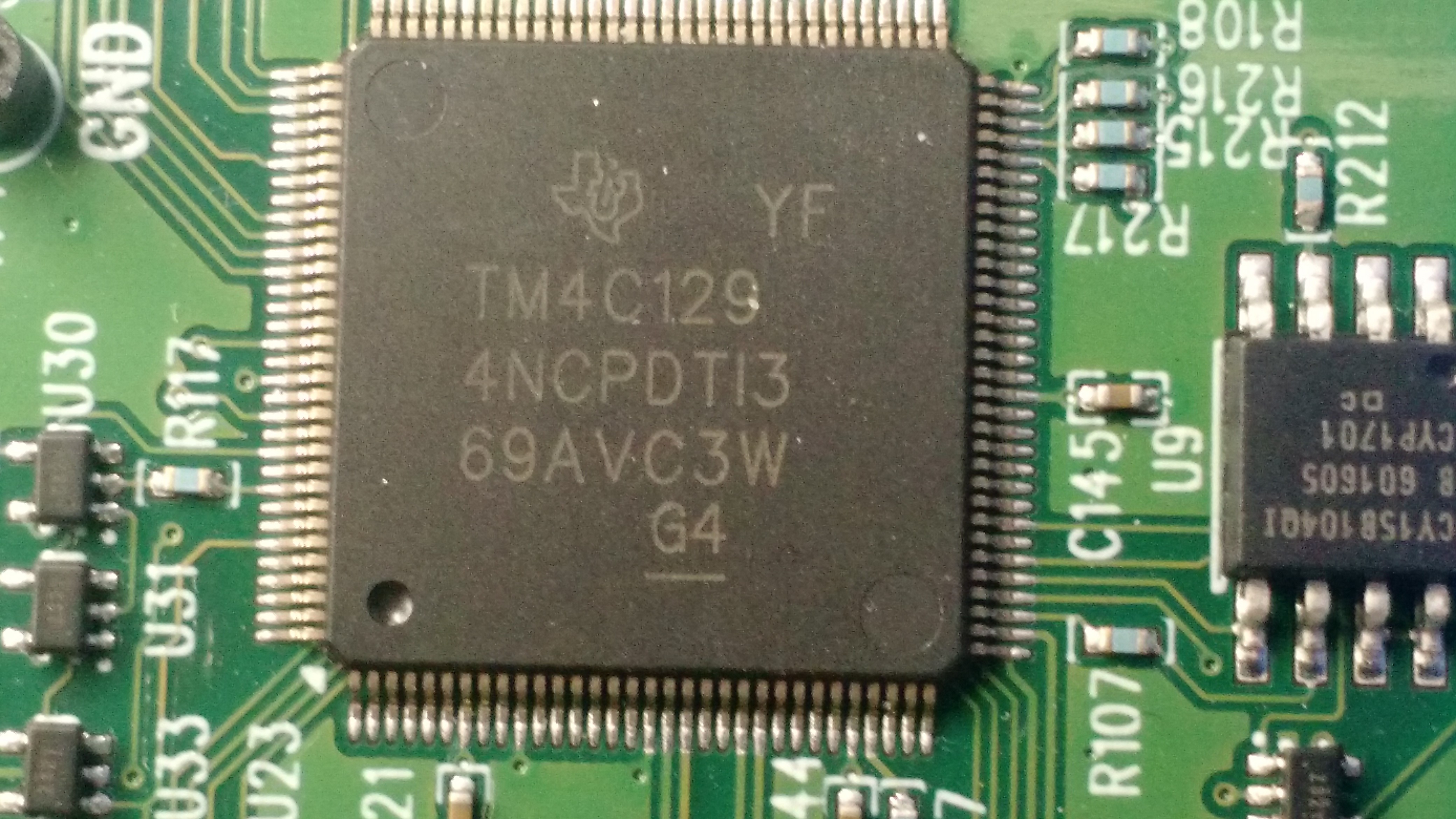
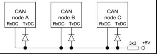
I have two nearly identical boards, using nearly the same core. They communicate via CAN Bus.

I have CAN Bus error occuring in only one of them. I made sure it is not a single board problem: it does repeat in the whole batch of 5.

Both boards us Artesyn DC-DC POL 12V / 3.3V converter for VDD, 3A capable unit..

The one that seems to work without problems has a separately derived VDDA, made from the external 12V power supply run via an isolated POL, and then a 5V LDO, and then a 3.3V LDO. (I do have a diode between VDD and VDDA in case the chip wants to lock up).

The one that has problems has the same 3.3V bus going to both VDD and VDDA, which is nothing unusual.

I decided to short the two voltages in the board that works (where the voltages are derived independently) and it started exhibiting exact same problem.

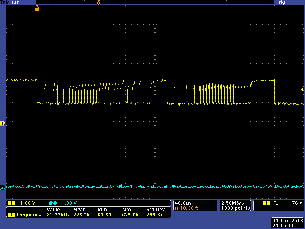
The rest of the board seems to work, the code runs fine until the CAN communication occurs at which point it signals an error.

This problem only occurs after a power-cycling: initially, when the board is programmed via the debugger without power cycling, it works fine.

In the Application Report SPMA056–October 2013, the "System Design Guidelines for the TM4C129x Family of Tiva™ C Series Microcontrollers ", I have this which I am not sure I fully understood:

3.4.1 Microcontroller Power Supply.

"The supply connected to VDD must accommodate a short period (40μSec to 60μSec) of additional inrush
current that occurs as the decoupling capacitors connected to the LDO on the VDDC rail charge up to the
VDDC voltage level. Internal circuitry limits the inrush to the IINRUSH(max) specified in the data sheet for the
part. The supply connected to VDD can self limit the current it supplies to something less than the
maximum IINRUSH, however that extends the period it takes to bring VDDC up to operating voltage."

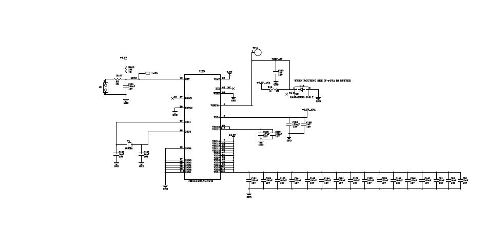
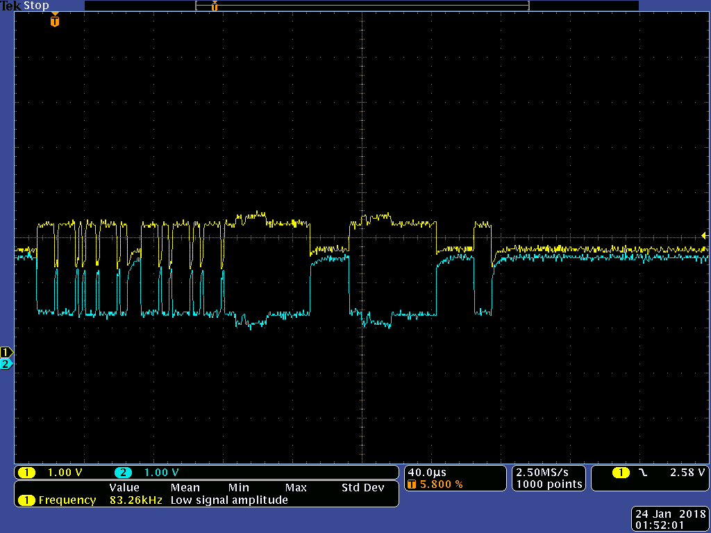
This is the setup of the board with the same VDD/AVDD.

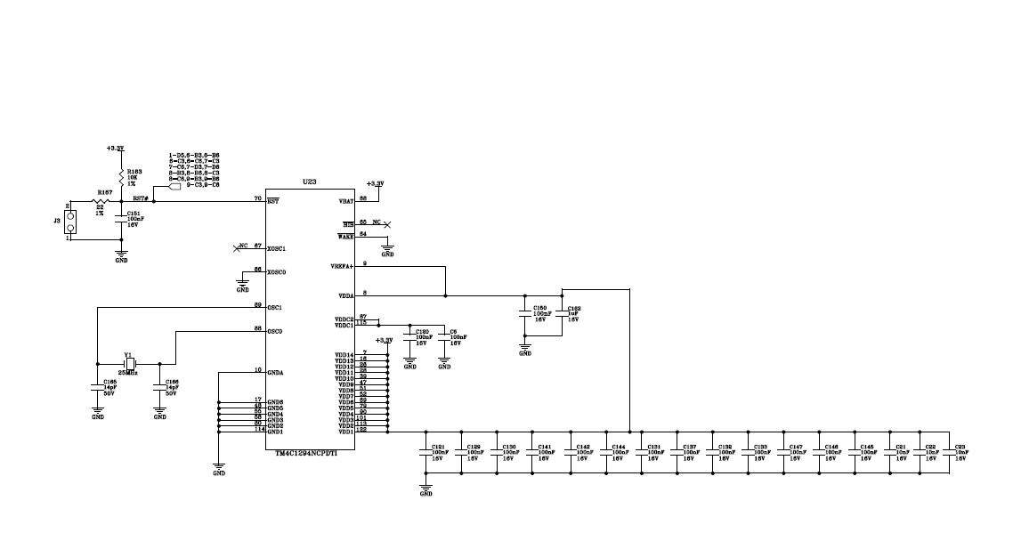
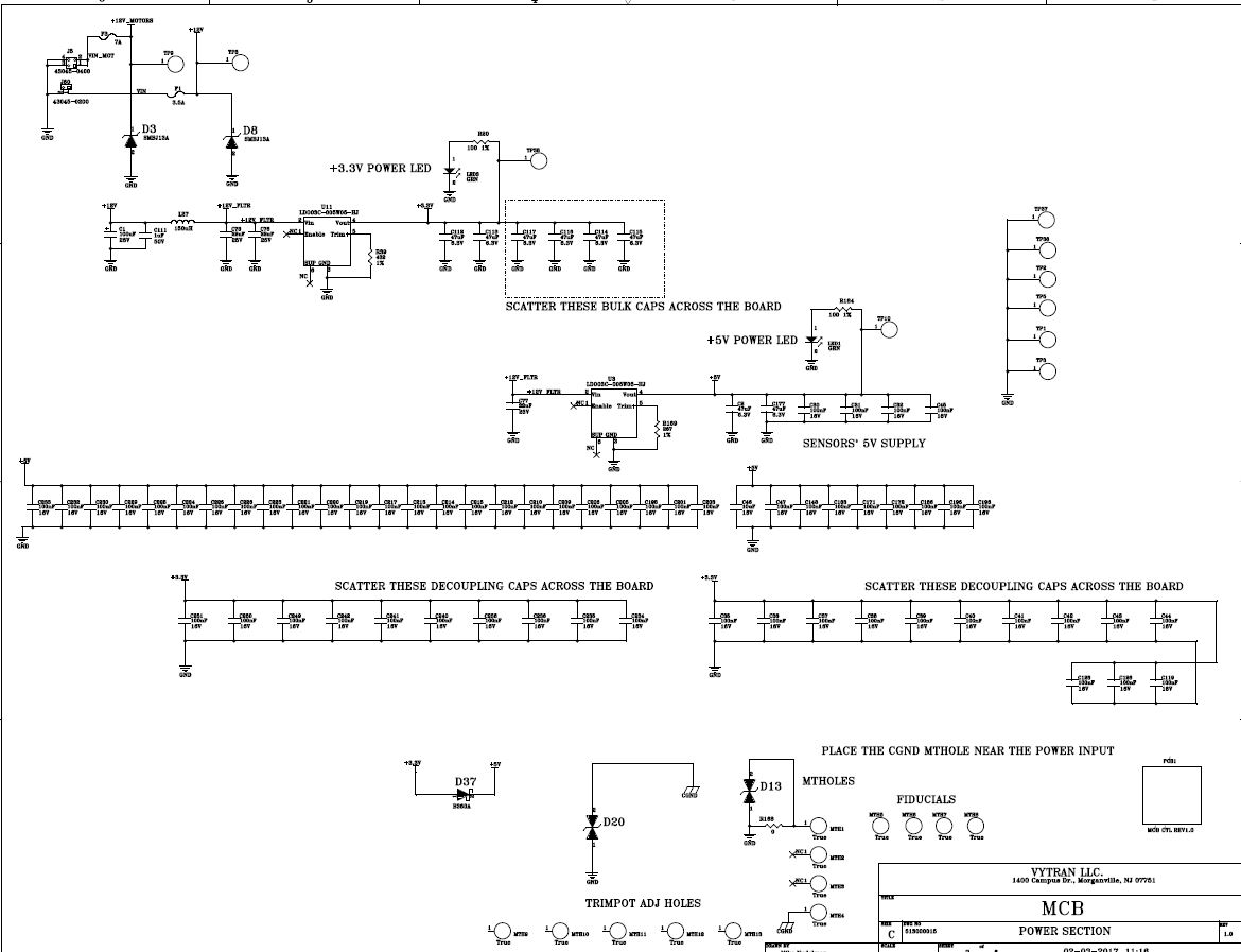
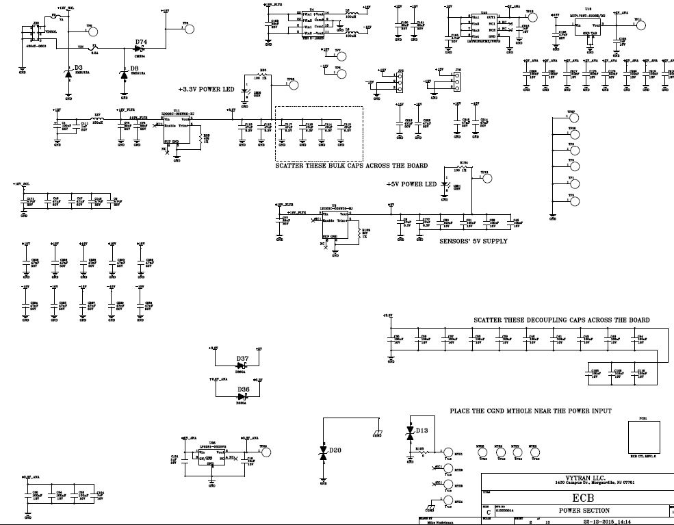
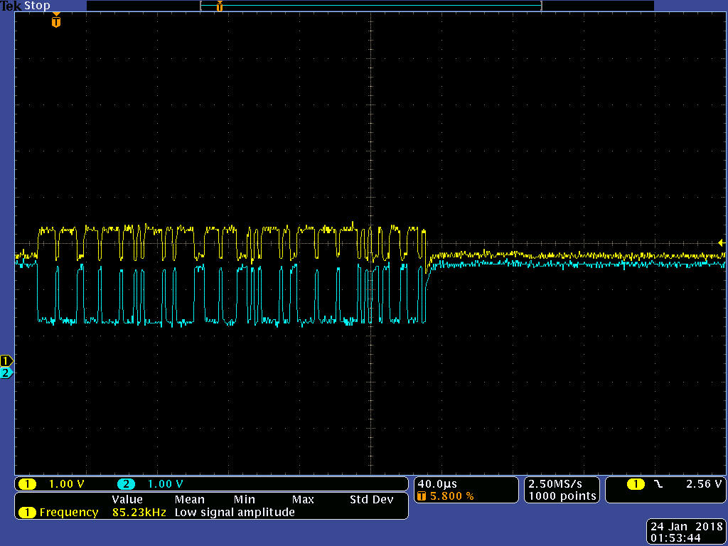
This is the setup with separate VDD/AVDD

  • Interesting. What type of CAN transceivers are you using and how are they powered? What is of particular concern is how the power for the micro side of the transceiver relates to the TM4C1294 VDD. You might want to look at the CAN RX line with a scope on the failing configuration to see the signal levels and if the signal follows CANL. Can you look at the CAN status register and tell what kind of error occurred from the LEC (last error code) bits?
  • Bob

    Thanks for looking at it.

    The transceiver is SN65HVD233D, shown in the upper right corner below. Powered by the same voltage as the VDD (that is directly tied to it through a ferrite).

    The signal levels are fine, both TTL and the CAN H/L. 
    Again, the two boards has exact same arrangement in that respect. If the two "good" boards (with separate VDD and VDDA) are programmed with the respective codes for the "good" and "bad" boards (they have different functionality but nearly identical core including CAN interface that I showed in the previous post), everything works fine then.

    If a "good" board has its VDDA and VDD tied together, it becomes "bad" and the CAN fails.

    Mike.


  • michael nudelman said:
    If a "good" board has its VDDA and VDD tied together, it becomes "bad" and the CAN fails.

    Does this not suggest that a,  "Timing Issue"  (between VDDA & VDD) likely exists - and (must) be accommodated?     When you "marry" those 2 pins - no such,  "Timing Accommodation" can be achieved - thus your issue launches...

    I'd follow KISS (as usual, of course) and (temporarily)  "Break the connections to the CAN Xcvr" - so its  "contribution"  (if any)  to your issue - may be muted.    (i.e. KISS - though banned here - STILL provides necessary insight & value!)      While you report,  "Only the CAN function as impacted - our experience w/such issues has revealed "issues across multiple peripheral modules" - the (temporarily) "broken connection to the CAN Xcvr" removes,   "ONE Avenue of suspicion!"     Suggest that the ADC (especially) be tested/verified - while such issue is "active."

    It is suspected that the current demands upon VDD  "exceed" those upon VDDA - which (may) enable VDDA to,  "Rise in advance of VDD" - proving problematic!    

    Firm/I have no experience w/"4C129" - and we employ HF & LF caps as well as ferrite bead - as close as possible to "4C123's"  VDDA.     Our CAN Xcvr operates w/out issue - I am (almost) tempted to "tie VDDA to VDD" and report - yet such "Risk" demands (some) "Reward" - does it not?

  • This is puzzling. We have used the SN65HVD233D with VDD tied to VDDA on the TM4C1294 before with no issues. Were you able to get the failure type from the LEC bits?

  • to cb1_mobile:

    I am not sure what "KISS" means....

    As to the VDD vs VDDA timing: they are the same bus, +3.3V in my sch, and physically are one extremely low inductance wide power plane. I am not sure how it is physically possible to have a timing issue here.

    I understand you are a factory TI engineer: can I supply you with the schematic off-line so you could look at it? I have employed this hookup with this very same uController (it is our staple uC part right now since we had migrated from Stellaris which also used the same hookup) before without problems, granted the CAN bus was not use so we simply do not know if it would act up. (With the STellaris I actually used this same setup WITH CAN bus and though this project never went to production but the software was written for it and the CAN worked just fine.)

    Question: are there any requirements on limiting inrush current in the VDDA on the power-up? I am not sure how it works, but in the "GOOD" board the VDDA, that is provided separately, has a very weak LDO providing +3.3V_ANA, while in the "bad" board it is a 3A-capable LDO.

    Anything I can do with ANALOG Brown-out/Reset bits after power-up to try to fix it?

  • Yes. We get the following errors: (from my software engineer)

    On the receive end we usually get error 2 –

    //
    //! A formatting error has occurred.
    //
    #define CAN_STATUS_LEC_FORM 0x00000002

    But occasionally error 1 –

    //
    //! A bit stuffing error has occurred.
    //
    #define CAN_STATUS_LEC_STUFF 0x00000001


    On the transmit side we get error 4 -

    //
    //! The bus remained a bit level of 1 for longer than is allowed.
    //
    #define CAN_STATUS_LEC_BIT1 0x00000004
  • michael nudelman said:
    I understand you are a factory TI engineer

    Such understanding proves, "Incorrect."     (we've no idea how such was formulated - firm/I are interested "outsiders" - serving multiple clients - here & elsewhere)

    I am contacting existing clients who (from memory) reported a situation (similar) to yours - yet it impacted "multiple MCU peripherals" (yet not ALL such peripherals).

    I also reasonably recall that - at least in some cases - the issue was "version related" - it might prove useful if you'd "photograph the MCU chip markings" - and provide here to Bob.

    We "like" your statement, "Anything I can do with ANALOG Brown-out/Reset bits after power-up to try to fix it?"     To begin - note & compare - then present - (any) differences between, "Good & Bad" boards.

    "KISS" describes a methodology proven to,  Speed & Simplify Problem Solving - most often achieved via, "Limiting the number of potentially impacting Variables - as much as possible - and by always creating a "Measurable Test and/or objective" - and not proceeding further until such test is passed/resolved.    Our preferred definition of "KISS"  "Keep It Simple & Systematic" (deal w/only ONE Variable at a time - when possible.)    Adding complexity - as so often presents here - is NOT the most efficient means to success!     (such is endlessly proven - over-ambition trumps "experience/basic caution" - runs rampant - w/few to, "sound the alarm!")

    May I note that such issue "Has been noted" upon the ARM MCUs of  "other vendors as well."      Yet I have confined my comments here to just those - as reported to my firm - by existing "TM4C" clients - employing a "129 class" MCU...

  • >>>Such understanding proves, "Incorrect."

    My hopes have been shattered :lol:

    Anyway, the chip version - see the pic below.

  • michael nudelman said:
    My hopes have been shattered :lol:

    Feel your pain - really.    (but very slightly...)

    Even a "near blind squirrel" (seen around these parts ... I am told) could read the chip markings (Ver) from that neat photo!    (might your camera lens - or God forbid - your MCU - need "blast of air?")

    As to "shattered hopes" - having co-founded - taken past tech firm public - "simple engineering job" holds,  "Not great interest."     

    Autonomous Auto software - and the A380's:  "10K sensors w/in EACH WING" -  along w/assisting VCs in "tech client Eval" - provides (some) resistance to, "shattered hopes."

  • These errors are indicative of speed issues on the CAN bus. I don't understand how connecting VDD and VDDA affects this. What baud rate are you using, how long is your CAN bus, how many nodes are on the bus? Please verify that you have 120 Ohm terminations on both ends of the bus. Have you tried communicating at a lower baud rate?

    One clarification, LEC = 4 indicates the device wanted to send a high (recessive) but the bus read as low (dominate). Since the transceiver drives the dominate state, but the termination resistors create the recessive state, the transition from dominate to recessive is usually slower than from recessive to dominate. The receive errors of bit stuff and format error can also be caused by a slow dominate to recessive transition.
  • That is the latest version of the silicon.
  • Thanks for that.

    And - any (near) similar (client issue) "Errata" is "not expected" under this "latest/greatest" silicon - is that true?

    To be complete - we should confirm that "each/every" (failing) MCU is as marked - as the photo revealed - should we not?

  • This is my co-worker's phone; mine refused to send the picture, but it came out the same: lighting plus the (actually very clean - just out of the package) surface texture make for what looks like dusty surface. I usually leave my Canon 5D and my Canon IS 100mm Macro lens at home when coming to work, although couple of times used it to make assy documentation. :) 

    Now, just to show the CAM waveforms (accounting for longish scope GNDs, but not much worse than I saw in the appnotes).

    The top to bottom - Good and Bad CAN communication. As you can see, in the case of the BAD the communication starts and then gets stuck at "0" (CAN levels spread apart), which is what one of the failure codes reflects.

  • I mean, BAD to GOOD, Bad is at the top and the GOOD is at the bottom pics respectively.
  • The scope caps (appear) to reveal different data - would not "identical data" prove more sound - easier to compare/contrast?

    As per "KISS"  (you're now an expert) - we seek to minimize variables.     (especially unnecessary - potentially confounding - variables!)

    Bob recently provided "Significant CAN error findings" - those should be fully reviewed/considered by your team.    (my group looking as well (in between completing their weekend plans) - first things first - you know)

    We must ask - "What induced you to "Tie the two Power Pins together?"     How did that come about?

  • I let my software engineer answer that, he's about to chime in, I think that was the attempt to send the same data but with Good/Bad results.

    But one thing I wanted to refresh on everyone's memory: IF the board is kept powered ON, AND is reprogrammed from the debugger WITHOUT cycling the power, everything works fine. No CAN errors at all. It all starts after the power cycle. So to me this means the CAN Physical part is OK.
  • >>We must ask - "What induced you to "Tie the two Power Pins together?" How did that come about?

    Do you mean in the design, or as the result of troubleshooting on the "Good" board?

    If the former, well, the board does not use analog part at all, and the ref designs show them tied together, which saves me analog / digital planes partitioning, using separate power sources, worrying about lock-up etc.

    If the latter, well, since two boards with otherwise identical cores behaved differently, and the difference occurred after power cycling, my sharp eye noticed that the same power/ different power for the VDD/VDDA was the sole difference between the two, so I decided to emulate the conditions in the Good board, and voila! - it did have the same exact effect.
  • I can "accept" why you'd think that - yet the IC IS expected to behave - under all (legal terms now) "Normal & Customary" conditions. And "Power Cycling" certainly fits w/in that "norm/cust" condition.

    It is our firm's experience - that such Power Cycling Issue - (usually - but not always) is found to result from "timing issues" - (somewhere existing w/in your design chain...) And - unfortunately - these (too often) prove "intermittent" - presenting among the "most difficult of issues to, "Identify and Resolve."
  • michael nudelman said:
    the board does not use analog part at all, and the ref designs show them tied together, which saves me analog / digital planes partitioning, using separate power sources, worrying about lock-up etc.

    Understood - yet as a past  Engineering Manager @  a similar  "Semi-giant"  - the analog portion of these MCUs  IS significant - and remains so - even if  "Not fully employed" - especially if,  "Not fully employed." 

    Our key clients & investors demand that we entertain MCUs from ALL ARM Vendors - indeed we comply - and our experience (across at least four ARM Vendors) reveals that,  "Proper Analog/Digital plane partitioning - just as you so well noted - indeed PAYS OFF!"    Repeatedly - even when - no use of the Analog sub-section (or limited use) is undertaken.     Again - the commitment of the MCU's silicon - and key/critical internal MCU routings - "WE FIND" - to deserve the, "Plane Partitioning" - along w/other critical factors - to warrant implementation.    

    The scope of this MCU's "VDD Power-Up errata" - which you yourself - noted & presented - causes rightful concern - does it not?

    When "Reference Designs" take (apparent) shortcuts - one wonders - was such (exhaustively) tested and well weighed/considered?      While somewhat "unusual" - it is not "unknown" - for clients (such as yourself) to unfortunately discover (potential) weaknesses w/in the "reference design."    

    Such has yet to be proven - more examination & facts are to be gathered - but to "Err on the side of caution" - rather than "hope/pray for the best" - enjoys some proponents...

  • That one is not even intermittent: it presents itself very reliably after power-up.

    One more thing I noticed when looking at the power-up of 3.3V that puzzles me.  I have two identical TIVA-based boards with the different power POL 3.3V DCDC's on it. I had to replace a vertical one by Lineage  (GE today) by an Artesy one which is horizontal, otherwise pretty identically behaving units, due to mechanical restrictions. Both units are 3A load capable.

    Here what I see: when the voltage rises around 2.7V or so, both units exhibit a 0.3-0.4V "dip" in the voltage. Considering the capacitance I have (all X7R chip caps, from 0.1uF to 47uF) is  about 300uF of pretty much ceramic chips across the plane, very low inductance etc with every pin decoupled, and the size is small, there should be quite a current surge on the processor part when it starts. I never saw that in the Stellaris.

    This is with the Lineage POL

    THis is with the Artesyn POL, same EXACT board.

  • Oh, yes - the yellow is power, the blue is the RESET signal.
  • Hi,

    I am the software engineer working with Mike. The data should have been identical, so even the beginning part of the BAD sample trace is showing problems.

    Scott
  • Thanks for that - we (appear) to have the 4 channel ver. (+ 16 Ch. mixed signal) of your scope.)
    For serious design documentation - it proves best to "label" the active channels. (looking at such "unlabeled caps" - months from now - will Save you Time "downstream!" (while clarifying efforts - Here & Now - again this is KISS!)

    I'd ask the vendor for their guidance as to, "best practice" for the powering of VDD & VDDA. (and I'd seek "beyond" the (existing) Tech boiler-plate doc. - unless "One & Done" is SOP. (Standard Op. Procedure - as you were unfamiliar w/ KISS.)

    Vendor's Bob has asked some insightful CAN based implementation questions - have you fully answered these? Or - at minimum - launched that process. I must depart shortly (some Profit Making is demanded) but can return late this eve - as/if desired. And crack staff/i "Work most weekends!" (we recognize - client interest/desire is *unlikely" to persist, forever...)
  • Hi Scott,

    Our posts just crossed - we could "Not have known" - thanks much for your clarification.
    Please do page back a bit - Vendor's Bob posed some most useful, "CAN Based questions" - as an "outsider" I'm (necessarily) a Tech Problem Solver - but minus the "vendor hoarded, inside info" - sometimes helpful in resolving such issues. (i.e. Car Repair from the 1960's...)
  • Bob

    Sorry did not answer this before.
    The rate is 100 KBaud/s.
    The bus is so short (2ft) it usually works with one terminator, but I do have 120 Ohms on both ends of the line.
    There are two nodes - the GOOD and the BAD boards (one is a general purpose controller of the device, and the other is a motor controller, receiving commands and giving readback via CAN). So it is point-to-point.

    The scope traces in a post before illustrate the PHY CAN bus. I can take a picture with short GND, but I think what I got so far indicates a decently functioning PHY CAN line.
  • Actually that is relatively slow and a very short CAN bus. Do you have a ground wire as part of the bus connecting the two devices?
  • Yes. Though it did not make any difference, but since my two boards were run independently from isolated power supplies (two halves of the benchtop type) I have the CAN connector as 3-way with Sig GND as the third wire.
  • I looked more closely at the scope shots. First, it looks like you are running at about 500K baud instead of 100K baud. The narrow pulses on the scope shot look about 2uS wide, not 10uS wide. (It looks like the horizontal sweep is 40uS/division.) But it should still work at that speed unless some of the timings are way off.

    If the two scope pictures are of the same message being sent, the first discrepancy is the third recessive bit after the start bit in the failing case (top picture). Is the device that gets the fail codes the transmitter in this case? If it is, it would be good to see a scope shot with the CANL signal from the transceiver and the CANTX pin from the TM4C. The CANL signal should never be high (recessive) when the CANTX pin is low. The long dominant phase is an error frame (6 or more dominant bits). It is likely the result of a previously detected error, not the actual problem.

    To eliminate hardware as the issue, can you run just some simple sample code between the two nodes? Are both nodes based off of TM4C129 devices? (Or can the network be setup that way?) Which pins are you using for CANTX and CANRX. I will see if I can whip up real simple CAN transmit and CAN receive routines.
  • Thanks Bob,

    You are right, we had been running at 500K but I reduced it to 100K to see if that would help. The scope shots were taken when still at 500K - sorry about the confusion. The transmitter always reports a CAN_STATUS_LEC_BIT1 error. The receiver usually reports CAN_STATUS_LEC_FORM but occasionally CAN_STATUS_LEC_STUFF.

    Yes, both nodes use TMC129.

    We will run it again and capture some new scope shots as you requested. I can also replace the code with simple transmit and receive code only to see what we get.

    Thanks again,
    Scott
  • Hi all,

    I've reprogrammed the boards to use the simple_rx and simple_tx sample code.  From the transmitter, this is what I am sending:

    uint32_t ui32MsgData;
    uint8_t *pui8MsgData;

    pui8MsgData = (uint8_t *)&ui32MsgData;

    ui32MsgData = 0x55555555;
    sCANMessage.ui32MsgID = 1;
    sCANMessage.ui32MsgIDMask = 0;
    sCANMessage.ui32Flags = MSG_OBJ_TX_INT_ENABLE;
    sCANMessage.ui32MsgLen = sizeof(pui8MsgData);
    sCANMessage.pui8MsgData = pui8MsgData;

    From a power off condition here is the scope trace of the CANH, CANL and CANTX. 

    Looks like all is good up until the ACK.  The transmitter reports CAN_STATUS_LEC_ACK.  

    Leaving everything powered on, but just reprogramming the receiving board (sending a hardware reset has the same effect) and sending the command again all is good:

    Scott

  • Hi Scott,
    Could this be a startup synchronization problem? If the transmitter starts before the receiving node has finished initializing the CAN module, the receiving module may be out of sync with the transmitter, failing to provide the ACK. That should result in a NAK from the transmitter and a re-transmission of the message. That re-transmission should then be properly received.
  • Hi Bob,

    The transmission only occurs when we initiate it so there is plenty of time for the receiving node to finish initializing.   The problem is very repeatable - always fails on first power up no matter how long we wait before we send the transmission.  And always works after reprogramming/resetting the receive node no matter how quickly we send the command after the reset.

    To simplify the scope trace, I used the CANRetrySet command to disable the retry.  Before disabling this the retry would fail as well.  Here's a trace showing this (with just the CANH):

    When the error condition is occurring, I have tried re initializing the CAN, clear all interrupts, etc and nothing seems to allow it to start working - only a hardware reset.

    Scott

  • Bob,

    Here's what I have done today:

    I used an LDO to create a separate +3.3V to feed to the VDDA.
    I lifted the VDDA pin alone, and connected it to an LP2981-33DBVR LDO output fitted with 4.7uF ceramic capacitor.

    First I used a 5V from a DCDC that is exactly the same as the 3.3V DCDC (adjustable type) as the input voltage.
    This did not result in any change in the board behaviour.

    Then I decided to introduce some delay into the VDDA and for that I put a 1kOhm resistor in series with the LDO's input and connected it to the common board input of 12V that feeds everything else.
    This resulted in a couple of ms delay of the VDDA relative to the VDD at the top part of the voltage rising edge, and after that the CAN bus worked fine.

    Scott and I repeated power-ups and it still works.
    Scott also used different versions of the software with the bootloader, and it is still ok.

    I did not see it anywhere that the VDDA delay is nesessary, and the VDDA originally connected to the VDD means that they rise exactly the same timing-wise at least at the chip's pins.

    So.....any comments?
  • To be honest, this still makes no sense to me. We probably have millions of boards with VDD tied to VDDA with properly working CAN. At this point I am unable to imagine a logical explanation to this behavior.
  • cb1_mobile said:
    Does this not suggest that a,  "Timing Issue"  (between VDDA & VDD) likely exists - and (must) be accommodated?     When you "marry" those 2 pins - no such,  "Timing Accommodation" can be achieved - thus your issue launches...

    Such was presented here:  Fri, 26 Jan - 07:42.    (very early into this "Diagnostic Process.")

    Appears to have succeeded - does it not?

  • Well. As a hardware guy, nothing would make me happier than to be able to blame the software (sorry Scott :) ) but in this case Scott so far has jumped through many flamed hoops and performed all possible songs and dances with tambourine while struggling with the software.

    And I myself suspect hardware.

    I have another board with the same type core (well, a ferrite separating the VDD and VDDA which for the timing purposes is same as wire) but that board has no CAN, and otherwise performs just fine, no problems. We could not verify CAN operation obviously since it has none.

    But we do have older Stellaris-based designs that were developed earlier with the same exact power setup that had CAN working, (We only switched to TIVA since the Stellaris got obsoleted) and I know so as the software was written and the CAN communication worked. I thought the two were fairly similar.

    Now, I do understand it might present a logical stumbling block, but we need to somehow proceed with the design, so I'd like to hear some guesses that are more educated than mine :)

    (Has it been up to me I'd never obsoleted Stellaris, that gave us mucho grief).

    Mike.

  • Does that "long past post" - which "so well" ID'ed & Resolved  your issue - not deserve,  "This post Resolved my Issue?"   (i.e. Green Button Click)

    We suffered the same (grievous) loss when LM3S was "yanked" - our use of (many) competing MCUs - adds (strategic) insight/understanding.

  • Hi Michael,

     Like Bob I can't really make sense why VDD and VDDA tied up will fail the CAN operation. I don't have a solution for your problem but I can think of some experiment for you to try. This is a more a process of elimination. I wonder if the failure has anything to do with the transceiver. Is it possible for you to establish the two-node CAN network with the below hookup using diodes instead of transceivers. See below figure. You need to use 3V instead of 5V on the bus. If it makes a difference such that it does not fail after the first powerup then it will lead us to focus on the transceiver. Since we are using diodes, please keep the distance between the two boards as short as possible. 

  • Sorry, I guess I didn't read all the past posts. Seems like you identify some timing issue between the supplies per cb1. You can disregard my earlier posting.
  • Hi Charles,

    Yours IS a clever/inventive suggestion - yet still - does such, "Restriction upon a "standard production CAN Xcvr"  prove "fair & justified?"       Is it (ever) fair to,  "blame the transceiver" - ESPECIALLY when - after an "MCU Reset" - the transceiver ... "performs without FLAW?"

    Did not the (very) strong, "Likelihood of  Supply Management/Timing Issue"  SCREAM OUT - yet was (unfairly & improperly) rejected?       Does not this PROVE the VALUE of  "Outsiders" - who have broader-based MCU experience/background - and thus prove,  "more likely" to have encountered such issues - and to have (already)  developed a Solution?

    Via our "deep dive" w/many ARM MCUs (many vendors) - we've noted such "sensitivities" - which may "NOT ALWAYS" (easily & readily) reveal.

    And may be overcome - by the suggestions - offered up ... (even) by  - sometimes especially by  -  outsiders...

  • Charles, thanks for the suggestion.

    I am not sure though what exactly this is intended to accomplish. If what I have done so far does not exonerate the transceiver, I wonder why you think so and what would prove it. It would be difficult to accomplish anyway - I'd have to remove all CAN PHY chips and then.....
    We have established the transceiver works as when I delay VDDA relative to VDD the communication is fine. Or when I connect them together on the working board, the communication ceases to function while you still can see properly operating levels on CAN bus in good accordance with the TTL RX/TX.
    Oh...and I use 3.3V on my CAN.
  • Well.....my issue has not been resolved, simply because even though I think I established with a good degree of certainty that a certain connection, and only in my board, only with my power setup, (simply because I do not have other boards with different power setup based around the same CPU that also have a CAN bus on them), causes CAN Bus to malfunction, it has not been established if this is 1) due to some problem with the chip itself, or 2) problem with something I've done, and 3) what needs to be done about it (I am not crazy about having to use a delay between the two powers only because I found out that in my board that makes it work).
    I need the real reason, inside or outside the chip, sounded out so I could treat the disease and not a symptom when re-designing the circuitry (if this is needed).
  • michael nudelman said:
    I need the real reason, inside or outside the chip, sounded out so I could treat the disease and not a symptom when re-designing the circuitry

    And - do you seek such, "real reason - inside/outside the chip - sounded out" for  "Each/Every"  other chip function - thus far  "observed" (one hopes) to behave to expectation?

    You apply a unique "Qualifier"  in this case - why is that?      Just as "vendor agents here" (most likely) have "Not observed" your issue - might "other issues lurk" - also evading (limited) vendor  observation?    (i.e. one and only one brand MCU - exercised/probed/observed!)

    I wish you well - my time/effort here appears both "thankless & fruit-less!"     You've "thanked everyone under the sun" - yet never - he who (4th post in) correctly diagnosed your issue!  

    Lack of  "full/proper observance of  issues" (YET) ... should not escape them from such, "real reason, sounding out!"     Good grief!     Have fun...

  • Hi Michael,
    I do agree your issue has not been resolved and I agree we have not identified the root cause of the issue. One thing that looks different to me is the rise time of VDD and VDDA. Yours looks like about 8mS. Our EK-TM$C1294XL launchpad has a VDD/VDDA rise time of about 300uS. On both (your design and our launchpad) you see a voltage drop at around 2.5V to 2.7V as the transistors turn on.

    I could theorize that the internal power-on-reset releases and the part starts to operate, but the slow voltage ramp causes the voltage to remain low during the CAN initialization, which causes the CAN to not work properly. But if that were the case, resetting the part after the power has stabilized would cause it to work properly. If I remember correctly, the opposite was true. A system reset while fully powered caused the problem to re-occur. Is that correct?
  • Hi Bob,

    No the reset does correct the problem and allows the CAN to operate properly.  So your theory may be correct.

    Scott

  • Well, if that is the case, delaying the rise of VDDA may be holding of the release of the internal Power-on reset (POR) long enough for VDD to stabilize. It would also explain why the device worked after being programmed by CCS, as power would already be stable when code execution starts.

    Your next question is likely, why would the part release its internal POR before the part can function properly? To make a long story short, the level POR is released varies somewhat with process. We have a tight range where it must operate. Too low, and the part does not operate properly, too high and it might not operate at the low end of the allowable VDD range. When POR is released, the part starts operating and consuming power. The increased current demand causes a voltage drop until the voltage regulator can compensate.

    If you cannot decrease the rise time of VDD, you might try delaying the release of the POR with the external nRST pin. the best way is with a precise external voltage monitor. The cheaper way is with an RC circuit on the nRST pin. If you might have a noisy power connection, such as when attaching a wire to 12V, you may need to add a diode (anode to the plus of the cap and cathode to VDD) .
  • CB1,
    I think you were the first one to be on the right track. But instead of the difference in VDD and VDDA causing the problem, the difference was likely masking the problem. At first I just could not get past the fact that so many boards work with VDD and VDDA tied together.
  • Bob,

    Thank you - you've identified a clever - yet subtle difference - in the "description of the issue."

    I can tell you - that as my earlier posts hinted - we had encountered (and resolved) this issue on (others') ARM MCUs - and passed such finding on - in the attempt to be of, "some value."

    Just as you note - that other vendor suffered a "process change" - which while gaining several benefits - imposed (new & unwanted) restrictions. We were fortunate to resolve such issue - and be well compensated for our time/effort...
  • Cb1,

    Thanks. You've been very helpful.

    All I'm saying is I want the factory analysis of what's been going on and suggested remedies.

    It seems like we're drawing nigh.

  • Bob

    Yes, now in the hindsight I wish I introduced an external RST supervisor, but so far we never had any problems and after 10 or so boards with Stellaris and two with TIVA doing just fine it never occurred to me to try that.
    Another way might be the Power Good from VDD enabling VDDA. Unfortunately the 3.3V POL I am using has no PG output, and using the 3.3V itself is risky as it does experience that dip at the top. Which also tells me that even if it were outfitted with the PG, it could flicker itself and I might end up with the same problem.

    BTW tomorrow I plan to look at the car val boards of which I have several and see how they are doing.