This thread has been locked.

If you have a related question, please click the "Ask a related question" button in the top right corner. The newly created question will be automatically linked to this question.

TM4C1294NCPDT: CAN Bus not working properly, power hook-up is a suspect.

Part Number: TM4C1294NCPDT
Other Parts Discussed in Thread: EK-TM4C1294XL

Hi everyone,

I have two nearly identical boards, using nearly the same core. They communicate via CAN Bus.

I have CAN Bus error occuring in only one of them. I made sure it is not a single board problem: it does repeat in the whole batch of 5.

Both boards us Artesyn DC-DC POL 12V / 3.3V converter for VDD, 3A capable unit..

The one that seems to work without problems has a separately derived VDDA, made from the external 12V power supply run via an isolated POL, and then a 5V LDO, and then a 3.3V LDO. (I do have a diode between VDD and VDDA in case the chip wants to lock up).

The one that has problems has the same 3.3V bus going to both VDD and VDDA, which is nothing unusual.

I decided to short the two voltages in the board that works (where the voltages are derived independently) and it started exhibiting exact same problem.

The rest of the board seems to work, the code runs fine until the CAN communication occurs at which point it signals an error.

This problem only occurs after a power-cycling: initially, when the board is programmed via the debugger without power cycling, it works fine.

In the Application Report SPMA056–October 2013, the "System Design Guidelines for the TM4C129x Family of Tiva™ C Series Microcontrollers ", I have this which I am not sure I fully understood:

3.4.1 Microcontroller Power Supply.

"The supply connected to VDD must accommodate a short period (40μSec to 60μSec) of additional inrush
current that occurs as the decoupling capacitors connected to the LDO on the VDDC rail charge up to the
VDDC voltage level. Internal circuitry limits the inrush to the IINRUSH(max) specified in the data sheet for the
part. The supply connected to VDD can self limit the current it supplies to something less than the
maximum IINRUSH, however that extends the period it takes to bring VDDC up to operating voltage."

This is the setup of the board with the same VDD/AVDD.

This is the setup with separate VDD/AVDD

  • I meant, eval board. Darn auto -corrector :)
  • When I entered, "car val" ... auto-corrector submitted, "eval."

    In our previous "cure" (again, another's ARM MCU) we provided exhaustively controlled, dual channel, drive voltages to (both) VDD and VDDA.      In that manner - the issue of "Power Sequencing/Quality/Impedance" became far easier to note,  then "set and adjust!"      

    That  controlled - driving/probing method - proved best by far - and enabled our,  "teasing out"  (deep) MCU "secrets."    (even though - especially though - that vendor (also) claimed to never have encountered such...)

  • Bob, Cb1,

    I thought this would be the closing of it as I tried to emulate a supervisory circuit by simply delaying the reset after the voltages stabilized. This is a board without the yesterday mod, where the VDD and VDDA are tied together, and now I, having performed a feat of soldering thaumaturgy, slapped a 0603 1uF cap on top of 0402 0.1uF cap having delayed the RST signal by at leas 10ms.

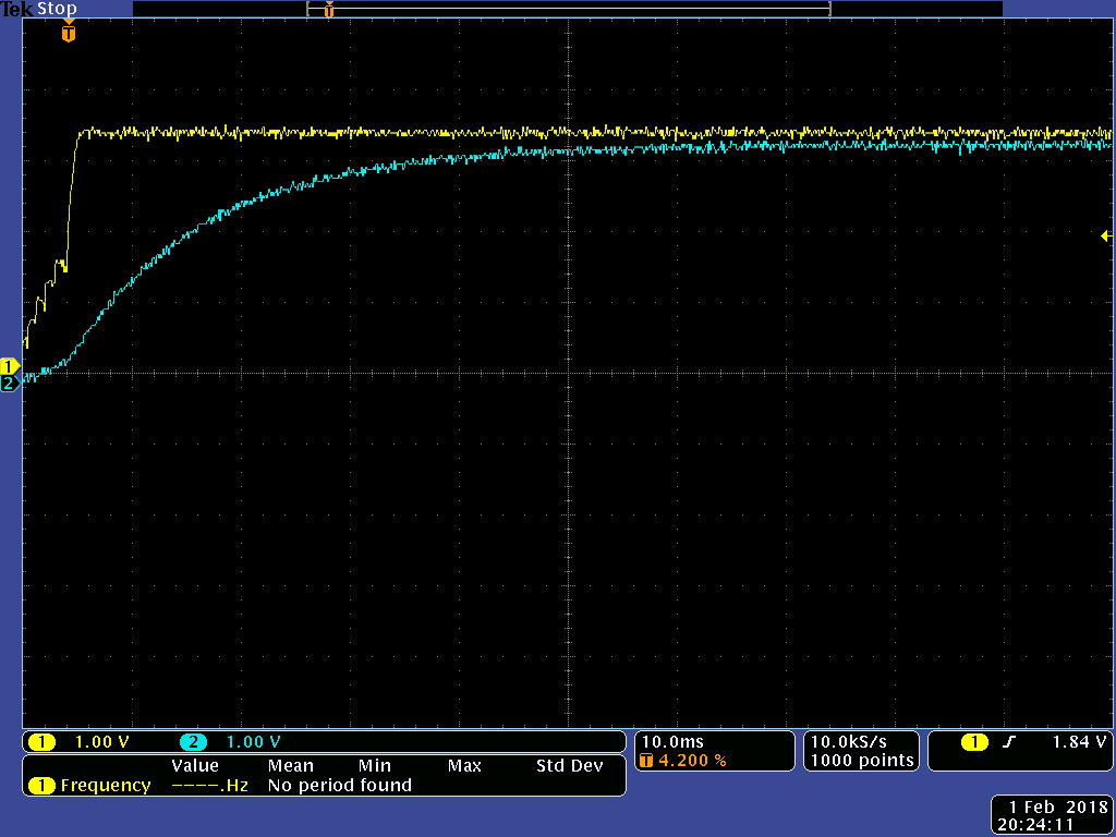
    Below is the +3.3V VDD (yellow trace) vs the RST (Blue trace) at 10ms/div - 1V/div. (VDD also represents VDDA).

    I fully expected that to work except...it didn't. Same error. 
    After performing a hard Reset, the board starts working.

    Am I missing something? Or is the Supervisor is not going to help and I need to increase the speed of +3.3V or delay VDDA vs VDD?

    Mike.

  • I would have expected that to work too. RST is well below 0.35*VDD when VDD hits 3V. How do you preform the "hard reset"? Is it by pulling the RST line low?
  • Yes, I have a 2-pin 100mil header, RST/GND, which I short.
  • I also wanted to play with the eval kit but I do not have booster boards so cannot work with CAN. But then I thought we had a pretty good understanding of what's been going on, and so I thought I could just work with my boards. :( Sigh......
  • How much bulk capacitance is on your board? Is it worth removing some to see if it decreases the rise time of VDD and if that impacts the problem.

    By the way, you have won my "stump the expert" award for this week. And keep in mind that I only consider myself an expert when defined as:
    ex: a has been
    spurt: a drip under pressure
  • Pardon - but firm/I always include (some) series resistor beyond the GND and MCU's Reset. MCU Reset pins ARE necessarily "complex" - and every effort should be made to, "Keep them safe - and happy."

    May I note too - that I remain doubtful that ONLY the CAN Behavior is "impacted" by this (VDD vs VDDA) issue.    It is "more than likely" that your testing has not been "fully comprehensive" (as was forced upon ours) and that "other MCU Peripheral areas" may  prove "disturbed" - as well.      (and ... not yet detected... due to the lack of comprehensive & systematic - multiple Peripheral Module testing)

    The fact that "Limited Testing" has not made such "discovery" - proves FAR from compelling!       (our "giant" clients would never allow such...)

    It is noted  that vendor Bob's "expert definition" (as noted by respectful, crack millennial staff) extends beyond,  "vendor agents."    (the (many) comforts of my car-trunk - await staff claiming such notice - (even) those claiming, "Difficulty in mascara application" - eased by the pleasing 6W, incandescence.)

  • Cb1,

    I am not sure exactly from your description where you place the resistor, but I also have a resistor, ,a 10-Ohm one, between the reset jumper and the capacitor, to "spark-proof" the jumper. While jumper can take that, I usually rely on this when I need for a MOSFET to short a capacitor as I have seen a pretty hefty FETs (3A-rated) get killed when shorting a 0.1uF cap charged to 5V, hence the 10-ohm resistor. Not sure we are talking of the same thing.
  • That (Tek) scope trace would have proved "even more valuable" had it included VDDA - as well. When such complex devices are "in play" it is rare that 2 channels (alone) prove, "adequate for task."
  • michael nudelman said:
    I am not sure exactly from your description where you place the resistor

    Our findings - any/all components "attached to MCU's Reset" should be mounted as "close as possible" to said Reset.    

    RF and other coupled/conducted noise arrive - more regularly and at higher levels - than ever in the past!        Your past writing to Bob avoided any mention of that "protective" series resistor.

  • Bob

    I use goodly amount of bulk but nothing stupendously high: 6 pcs of 47uF ceramics, which is 282uF plus possibly under a 100pcs of 0.1uF chip caps (I am usually generous on decoupling) which add 10uF to the bulk. I am talking of the capacitance at the output of the +3.3V DCDC. Can I reduce it? yes. But 300uF is not that much.
  • Cb1,

    The mounting is VERY compact: I use 0402 components and my decouplers mostly right at the pins and more of that sprinkled around across the plane, my resistors are the same way, it is all so tight that to mount that extra cap today I really had to use all my soldering skills.

    As for the showing VDDA separate from VDD, it is not truly possible as it is off of the same plane as the rest of the VDD pins. Same solid unpartitioned +3.3V plane and same solid unpartitioned GND plane. The scope I have will not show the difference even if using "Exacto knife" GND. So, I would say, the VDD trace is very accurate representation of the VDDA down to a microvolt and even below (I know so as a very similar board based around the same CPU measures uVs and pretty successfully so).
  • If I may ... (Bob operates under constraints) we outsiders are "More Free!"

    Give Bob "More info with which to work!"    He "hints" at reducing that cap load - of course you should - "DO just that."    You have entered "poorly traveled territory" - possibly "NEVER traveled territory" - for vendor agents.     Not so for this reporter - who has "Solved such an Issue!"      (and been handsomely rewarded in such process...)

  • Oh....speaking of the resistor, it has been shown in the sch provided, that is repeated on every page :)
  • That "repetition upon "every page" ... more properly ... should note "Repeated on every "Deeply Buried, Far Past Page" - should it not?
    Our posts just crossed - yet our "inability of mind melding" continues.

    It is not your "hapless helpers' duty" to "dig for such facts" - such should be presented by you - for helper ease!
  • Bob

    Another thing, I just went to the datasheet for the power supply I am using, LDO03C by Artesyn (or are they Emerson today?) to see the max load capacitance: it seems that my value should be between the one listed for the outputs of 2.5V (1000 uF) and 5V (500uF) (they do not list 3.3V) - that is if I were to extrapolate coarsely,  this would be about  840uF max at 3.3V. I have under 300uF.

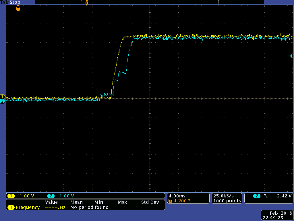
    Now, I rigged up a unloaded LDO with only on-chip capacitance and compared it with the board's one.

    Here's the pic. As you could see, although the start-up itself on the board is delayed due to the way the LDO handles the capacitance, the slope slew rate remains the same.

  • Hi Michael,
    I was afraid that the slow VDD rise time was inherent to the supply when you told me you only had 300uF of capacitance. What is confusing me is why the capacitor on RST did not work, but asserting RST later does. Can you try powering up with your jumper holding RST low and then removing the jumper?
  • I guess I can....though let me ask Scott first, I think we did that.
  • Bob, yes we did that, but we did this again just to keep honest.
    I installed the reset jumper and powered on.
    Then I removed the rest jumper (delay equal several seconds....infinity for all intents and purposes :) ) and we had the error.

    Then I installed and removed the jumper while staying powered, and the communication worked.

    It is almost that the supervisory circuit has to create a full up-down-up pulse for it to work.
  • More takes:

    I have decided to see if the lab power supply (3A/output or 6A parallelled) rise time affects the situation. The RESET is still staying delayed as before.

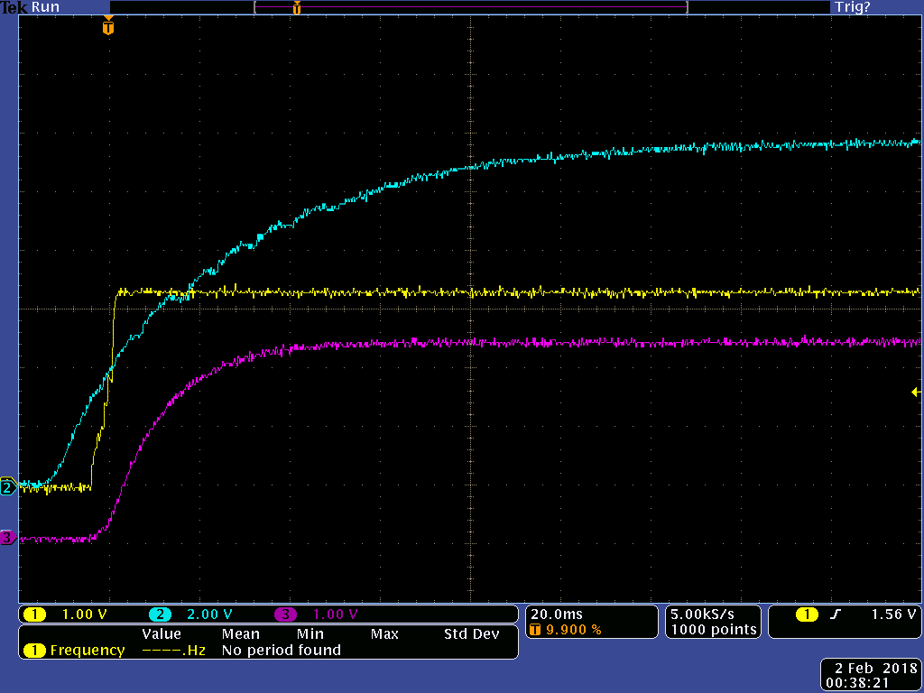
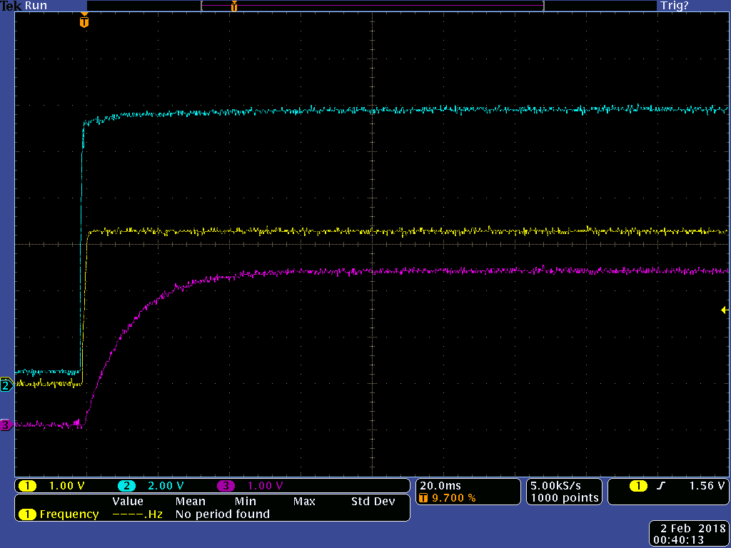
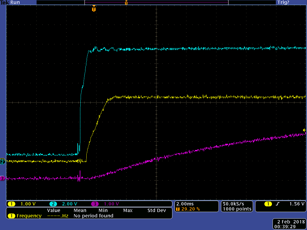
    For this I first took the picture of +3.3V  VDD (and VDDA) rising as the power supply is powered by pressing the "Power button". As you can see in the pics below, the 12V rises very slow and the VDD has those "steps" on it - obviously due to not enough difference between the Vin and Vout.

    Again, Yellow is VDD, Blue is 12VIN and the Purple is the RESET.

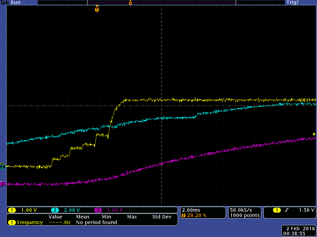
    And the blow-up of the same.

    Sure enough we are having the error.

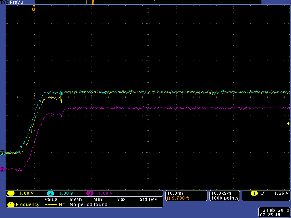
    Then I pre-energized the lab power supply and powered the card by plugging in the wire into the supply's Positive. That took care of the slow risetime.

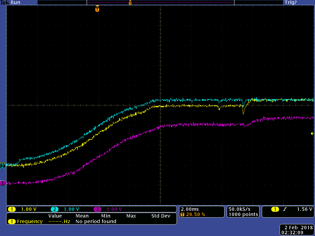
    As you can see, no steps anymore, clean nice slope of the VDD, and, of course, well delayed RESET.

    And the blow-up at 2ms/div

    Everything is just nice. Except.....still the error, and consistently at that.

  • The last two experiments suggest that it is not as simple as corruption due to starting execution before the power has stabilized.

    Is it possible that the software takes a different path on a power-on reset as opposed to an external reset or a brown-out reset? To do that the software would have to read (and clear set bits in) the reset cause (RESC) register.
  • Hi Bob,

    I'm pretty sure we aren't doing anything like that.  I just checked the SimpleRx project that I sent to you and this is all I see in startup_css.c:

    //*****************************************************************************
    //
    // This is the code that gets called when the processor first starts execution
    // following a reset event. Only the absolutely necessary set is performed,
    // after which the application supplied entry() routine is called. Any fancy
    // actions (such as making decisions based on the reset cause register, and
    // resetting the bits in that register) are left solely in the hands of the
    // application.
    //
    //*****************************************************************************
    void
    ResetISR(void)
    {
    //
    // Jump to the CCS C initialization routine. This will enable the
    // floating-point unit as well, so that does not need to be done here.
    //
    __asm(" .global _c_int00\n"
    " b.w _c_int00");
    }

    In our main() we aren't doing any checks of the reset cause.

    Scott

  • Bob

    One more experiment (the more the merrier).

    We have another board that we are using pretty widely. It functions just fine in every respect that we are using it for: it runs A/D, SPI Bus, communications (USB, I2C, Ethernet and RS-232), and multiple GPIO (to run Stepper Motors etc).

    I have just remembered that at the request of one group, "just in case" (it has never been used) I introduced a hookup for CAN Bus also.

    Now, this board has separate VDD and VDDA, but unlike in the board with working CAN  (the one that works) while VDD is derived using exact same POL, the VDDA is derived the same exact way that I did in the experiment with the non-roking CAN board, when lifting VDDA pin and running it through an LDO connected to the 12Vin. So unless delayed with a resistor and an input cap, it will appear much sooner. As you remember, before I introduced the resistor, the non-working board still did not work, and then due to the delay after introducing 1K resistor between 12Vin and the LDO input it started working.

    So in the same exact fashion, the VDDA is derived as series of the two LDOs from 12Vin - 12V to 5V LDO, and 5V to 3.3V LDO becoming the VDDA.

    So, when having connected the board to the CAN bus, we have achieved exact same result as in the board with the non-working CAN: right after programming the code the board communicates fine, and after power cycling it goes into CAN error.

    The interesting thing is, the VDDA is just a little ahead of the VDD.

    These are the scope captures of the voltages and the reset.

    The Yelolow is the VDD, Blue is VDDA and the purple is Reset.

    And the blow-up

  • I just want to emphasize this: in the last board discussed in the previous post, though I am sure we are not using every single resource the CPU provides, we use quite a bit. There are no problems with anything we are using in this board. Including the analog portion that we use to measure signals provided by a load cell. Ethernet communication works fine. USB communication works fine. I2C communication that we use to provide extra GPIOs using IO expanders, works fine. SPI bus used to talk too D/A converters and to read/write the non-volatile memory, works fine. GPIOs that we need to provide step signals (which requires working with timers to provide speed accuracy) for stepper motors, as well as those asynchronous GPIOs responsible for enables, directions, and micro-step commands are all fine. And, of course, there's the Heartbeat LED.

    CAN is the ONLY function so far that is sensitive to whatever is going on with the power-up sequence.

    Oh.....just to anticipate the question, the CPU latch-up due to VDDA leading the VDD is prevented by the Schottky diode between the two, the VDDA driving the VDD.
  • Are you running the application at 25MHz like the simple_rx project? I had trouble with that project receiving data from an NI GPIB CAN controller, but it could receive from another EK-TM4C1294 launchpad using a simple_tx project. On closer analysis, I saw the single CAN bit width was 15.5uS, not 10uS as expected. I changed the system clock from 25MHz to 120MHz and now the bit width is 10uS.
  • Bob

    Scott can answer it better but we do run at 25MHz which is known to do weird stuff if the Ethernet bias resistor is not installed, which is installed, and that did cross my mind except there's that other board that runs fine. Unless there's combination of 25Mhz and the power sequencing at the same time....

    I use 25MHz core as the other boards we have all run Ethernet, so it is easier for me touse the same crystal, caps etc. Although one would think, if runing Ethernet why use CAN. :)

  • Hi Michael,
    Sorry, I meant to ask about the system clock speed, not the crystal. Do you use the PLL, or run the system clock at crystal frequency? I have been swamped this morning, but plan to dig deeper on the CAN baud rate issue at 25MHz this afternoon.
  • It is not my intention to, "Poison these diagnostic waters" - yet as we await vendor Bob's schedule battling - I believe it useful to present issues for,  "Post Bob's arrival & analysis."

    michael nudelman said:
    This problem only occurs after a power-cycling: initially, when the board is programmed via the debugger without power cycling, it works fine.

    This thread (now) reaches to 80 posts - and that (very) size - makes "total recall" difficult.    If what I seek - here/now - has been answered (I apologize) ... here goes:

    Is it true that the (only) time in which,  "successful CAN operation occurs" is:

    • with the debugger attached
    • after programming - again w/debugger attached

    Now - if either (or both) of the above has occurred - and then the debugger is removed (ideally disconnected) - what then?     Does correct CAN operation continue?     Also - are external JTAG/SWD pull-up resistors being employed?   (Not internal (too high in value) MCU resistors)

    michael nudelman said:
    The one that has problems has the same 3.3V bus going to both VDD and VDDA, which is nothing unusual.

    While this (may) qualify as, "nothing unusual" - this "eased" connection proves VERY FAR from optimal...    Our "solution" reveals the "independence of  VDD & VDDA" - to be greatly advantageous.

    My firm has succeeded in correcting (similar)  "Post MCU Reset" issues - experienced by TWO Different ARM MCUs - provided by (2 other) ARM MCU vendors.    

    Such "correction" may (not) qualify as, "universal" - and has proven to be (somewhat) "MCU process related" - yet when deployed - proved the "BEST & ONLY Means" to enable (reasonably full - potentially completely full) MCU operation.     

    To not "muddy the waters" for Bob (and his/others' methods) firm/my preference is to let  "Vendor Analysis/Insight" proceed - and should that fail -  only then present our findings!

    Kindly advise if these findings (our findings) are desired.      (to arrive after:  Bob's/others' effort/extended "fix direction...")

  • Hi Bob,

    Our application is configuring the clock the same as the SimpleRx application does:

    g_ui32SysClock = MAP_SysCtlClockFreqSet((SYSCTL_XTAL_25MHZ | SYSCTL_OSC_MAIN | SYSCTL_USE_PLL | SYSCTL_CFG_VCO_480), 50000000);

    Scott

  • cb1,

    any findings pertinent to the issue are interesting.

    This said, the very TI's ARM Cortex Stellaris in this respect behaves differently from TIVA.
  • michael nudelman said:
    ... the very TI's ARM Cortex Stellaris in this respect behaves differently from TIVA.

    And too - the (many) ARM MCUs of (others) - which (also) presented "differences in process."       What "once had worked" - may not continue (completely) - especially w/in the "special conditions" you/your firm present.        I would ask - how often had (anyone) ... (even Bob) ... run the CAN Module - immediately after an MCU Reset?      (which generates  "your"  CAN failure's onset!)

    Beyond  "findings being interesting" - multiple questions were asked - answers not  (yet) provided...        Those "answers" prove "interesting" too... (potentially "game-changers"  for you...)

  • Hi,

    These are the conditions under which we are able to get the CAN to operate correctly:

    1) reprogramming the receive node after power cycling (once reprogramed, the debugger can be left attached or removed)
    2) send the hardware reset command from LMFlash Programmer
    3) manually trigger a reset by momentarily pulling the RST line low
    4) adding logic to our application to trigger a reset the first time running after a power cycle by writing NVIC_APINT_VECTKEY | NVIC_APINT_SYSRESETREQ to register NVIC_APINT
    5) delaying VDDA

    Obviously methods 1,2 and 3 will not help us long term.
    Option 4 might be a solution, but is ugly and it occasionally has failed - possibly I need to delay before triggering the reset
    Option 5 is probably the preferred solution that we know of today, but will require a new spin of our board. Before doing this we would like to understand exactly the cause and the requirement for this delay so that we are confident that our design change will be a robust solution.

    Scott
  • Thank you - your detailed response much appreciated.

    Your "option #5" embodies "PART" of my firm's (proven) solution.     (proven upon 2 - previously failing - ARM MCU models - from 2 different ARM MCU Vendors - created after  "each vendor's effort to fix"  -  had failed!)

    I must note that (still) our focused questions remain unanswered - which degrades our ability to fully/properly glean understanding...

  • Bob,

    while Scott is answering to you and to Cb1, here are some of my thoughts.

    I can re-design the board using what we've learned about the power sequence. I would hate to change the POL I am using so I could possibly try to use the very VDD as the PG signal for an LDO or, say, MOSFET that then applies VDD to the VDDA. Plus delayed RESET, a supervisor with voltage monitoring and such. I am sure that if I leave enough hooks, some configurations will work fine (at this point I wish I had a booster pack with CAN on it so I could use the EK-TM4C1429 board to try to duplicate the symptom but then I do not have it and I am not about to start prototyping, unless someone sells it cheap).
    But before I build the board, now that I know there is an issue, whether it is something that I am at fault of or not, I'd like to see some factory analysis of what it is that is (or is not) on the books that I've violated (or maybe we are not aware of 'till now), as I have that proclivity to at least try to design by the guide, if one's available.

    I have not seen any drawing that is similar to what other vendors often show, where the VDD/VDDA/VDDC and such voltages are shown rising relative to each other. All I saw is this:

    >>>>>>Tiva C Series uControllers require only a single +3.3V power supply connected to VDD and VDDA. (spma059 app. report).

    Without any official guidance re-designing the board for me, even if it results in a perfectly working board, is still off-the-label guess-taking design, and I'd like to avoid that to the extent possible.

    So, I do not know if there is a simulator of some sort that you guys might have somewhere, that could be used to simulate the situation, or maybe you have that EK-TM4C1429 eval board with a CAN boosterpack 2, that you could try with a single power source, or something else you could think of, but I'd like to know why it is doing this when it says it should be working with just one supply (and, well, if one disregards the CAN, it kinda does!)

    Best,

    Mike.
  • Hi Mike,
    I totally understand the need to find true root cause before redesigning the board. I am using an EK-TM4C1294XL launchpad trying to reproduce your issue. I do not yet like the idea of just delaying VDDA because that solution does not make sense to me. This week my time was somewhat limited as it is my week to answer the majority of forum questions. I hope to have more time to devote to this issue next week. That said, I will still be working on this issue this afternoon.
  • Thanks, Bob, will be waiting for your findings.
  • Hi Mike and Scott,

    Are you setting the CAN baud rate in your application like you are in the SimpleRX project you sent me?

        CANBitRateSet(CAN0_BASE, SysCtlClockGet(), 100000);
    

    The function "SysCtlClockGet() is not valid for the TM4C1294 devices. You can hard code the system clock  value as 50000000, or do something like:

        uint32_t ui32SysClock;
    
        ui32SysClock = SysCtlClockFreqSet((SYSCTL_XTAL_25MHZ |
                                               SYSCTL_OSC_MAIN | SYSCTL_USE_PLL |
                                               SYSCTL_CFG_VCO_480), 50000000);
    ...
        CANBitRateSet(CAN0_BASE, ui32SysClock, 100000);
    

    Since the value returned by SysCtlClockGet() on a TM4C1294 device is unpredictable, it may very well change based on how the device powers up. This could be the root cause.

  • My bad. Looks like you found the problem. We just gave this a try and it looks like this was the root cause. Thank you all for your help with this and sorry to have taken so much of everyone's time for this mistake.

    Scott
  • Bob

    Thanks, seems like this is it.
    Appreciate all the help.

    Cb1, also, thanks.

    We should consider it resolved for now.

    Mike.
  • Hold on!    

    That SAME coding "mistake" MUST EXIST in your (other) Equally NEW boards - which were reported to work!        (and which - independently powered VDD & VDDA!)      Or - did your software employ DIFFERENT System Clock coding - for those boards which separated VDD & VDDA?

    How is that explained?

    I still argue & advise against the "marriage" of VDD & VDDA.

  • cb1_mobile said:

    Hold on!    

    That SAME coding "mistake" MUST EXIST in your (other) Equally NEW boards - which were reported to work!        (and which - independently powered VDD & VDDA!)      Or - did your software employ DIFFERENT System Clock coding - for those boards which separated VDD & VDDA?

    How is that explained?

    I still argue & advise against the "marriage" of VDD & VDDA.

    Cb1,

    To quote Bob,

    "Since the value returned by SysCtlClockGet() on a TM4C1294 device is unpredictable, it may very well change based on how the device powers up."

    So, if we are dealing with a function whose value might depend on power-up condition, and the latter is pretty repeatable within the same type of the board, we could have two different types of boards having different, but repeatable initialized values. So the fact that one board worked, now in the hindsight, might not be what we thought.

    What it could've been is that we used two of the SAME power set-up boards that initialized similarly. Once I converted the other board it initialized similarly to the first.

    What we did NOT try (and we could just for the heck of it on Monday next week) is to take the two BAD (married VDD/VDDA) boards and see if they talk to each other. Now I think they just might.

    So there might NOT be working/non-working boards, but just boards with different Baud rate initialization values. Which, as I said, we could try Monday if Scott feels like it :)

    Mike.

  • Your call of course - yet the lack of "consistency" between the boards - and this "fix" - sends "chills" thru our group...

    I believe - still unexplained - is how "Different Code"  (or allegedly different code) runs FINE under the debugger - and then FAILS - when the debugger departs!

  • CB1,

    No the code did do no such thing. I ran after being programmed using debugger as a programmer, and would keep running after removing the debugger, only to fail after the Power Cycling. The reason, methinks, being that he programmer issues the Hardware Reset to the RST pin upon completing the programming- as we know, RESET going Hi-Lo-Hi while the board being piwered has always made the board run correctly.

    AMOF we have not even used debugger as a debugger so far - we used it as a JTAG programming pod.

    Let's wait till Monday, I want now to do that two bad board experiment.

    Mike.

  • My friend - you've earlier stated that you have two somewhat different board implementations.     It must be assumed that both - in terms of System Clock setting code (at minimum) were identical.     This much is agreed - is that so?

    And it was (now nearly 90 posts deep) just discovered that the System Clock was programmed w/an improper (past MCU) code implementation.
    If both sets of your,  "two somewhat different board implementations" employed the "same code" (again - as far as System Clock setting is concerned) ... then,  "How is it explained that one board set "worked" - the second failed?"

    Has this "statement of fact" been fully/properly recognized - and if so - how do you account for the fact that, "one board set worked - even with - and especially with - a deficient System Clock setting?

    If this issue resulted (only or primarily) due to "unique interconnect of boards" - may I then submit that such "interconnect detail" was improperly/inadequately noted - and should have received far more "emphasis."

    Vendor's & my goal was to assist in your success - I believe that the points raised here - operate to your long-term success...      (and the implementation of a "real & lasting cure" - which I fear may not be in "clear evidence.)

  • And a good Monday it is. Hello everyone.

    So as I promised Friday, I did that experiment that probably would speed up the troubleshooting but then we never did it then.

    We took now two "bad" boards, that is the board where the VDD and VDDA tied together and that in the past refused to talk to the "good" board where the VDDA and VDD are separate and the VDD is leading VDDA during the power up.

    So far Bob's theory has been that the initialization is dependent on the power set-up and the two boards initialized differently, and this is why they started talking to each other when we fixed that issue due to the init command that supposedly not working in this uController.

    I theorized on Friday that if this is the case then the two "bad boards" with the old code in them still should talk to each other as they initialized similarly, for the same reason the two "good" boards talked to each other before.

    So today I took two "bad" boards fresh from the bin, no mods at all, hooked them up and Scott put in the old codes in both of them without the initialization function correction.
    The boards talked to each other, both right after programming and after we performed power cycling.

    I think that gives support to what Bob thought was happening.

    That is, without the correction two boards of the same kind (two "bad" or two "good") will talk to each other while two boards of different kinds won't ("bad" to "good").
    After correction any board will talk to any other board ("good" to "bad" or "good" to "good", or "bad" to "bad").

    I don't know if Bob wants to provide some last thoughts to dispel whatever fears we have left; he's welcome to do that.
    Scott meantime said he'd like to look at the init values and at what the init finction returns.

    Mike.

  • Michael, Scott,

    Glad to hear that things are now working as expected. We could delve deeper into why the function SysCtlClockGet() (which is not valid for the TM4C129 devices) returned different values in the two board configurations, but that would only be an academic exercise. I want to thank both of you for being persistent and not accepting a workaround without a full understanding of the problem. That attitude reflects well on your product quality.

    CB1,

    Just one clarification. They used the proper function to set the system clock frequency, the problem was then using the wrong function (or wrong method) of passing the system clock frequency to the function which sets the CAN baud rate.

    To me, the interesting question is how to prevent this confusion in the future. It would have been nice if in TivaWare we used the same functions (and methods) of setting the system clock rate and returning the system frequency, but that horse has already left the barn. We did include an ASSERT statement in the TivaWare source that checks that the function is called on a TM4C123 device. Unfortunately the overhead and extra effort to build a project with ASSERTs enabled often preclude their use. Nonetheless, perhaps when I get my head above water (which says a lot from a person who lives on a boat) I can put together an application note explaining how to use them.

    uint32_t
    SysCtlClockGet(void)
    {
        uint32_t ui32RCC, ui32RCC2, ui32PLL, ui32Clk, ui32Max;
        uint32_t ui32PLL1;
    
        //
        // This function is only valid on TM4C123 devices.
        //
        ASSERT(CLASS_IS_TM4C123);
    ...