This thread has been locked.

If you have a related question, please click the "Ask a related question" button in the top right corner. The newly created question will be automatically linked to this question.

TM4C129ENCPDT: SST25VF016B Flash EEPROM SPI Problem

Part Number: TM4C129ENCPDT

Hello,

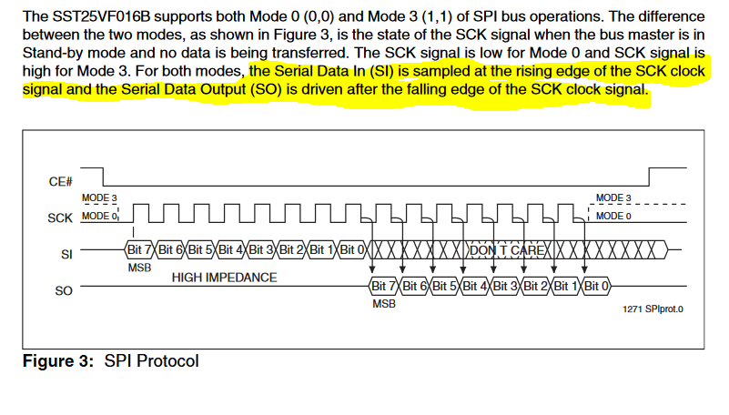
I'm trying to use spi communication between TM4C129ENCPDT and SST25VF016B.

I read some other post in forum but couldn't achieve send and read any byte. I can read JEDEC ID. Here you have my code. Waiting for responses.

//INITIALIZATION

unsigned long ui32Trash;

SysCtlPeripheralEnable(SYSCTL_PERIPH_SSI2);
SysCtlPeripheralEnable(SYSCTL_PERIPH_GPIOD);
SysCtlPeripheralEnable(SYSCTL_PERIPH_GPIOQ);

GPIOPinConfigure(GPIO_PD3_SSI2CLK);

GPIOPinConfigure(GPIO_PD0_SSI2XDAT1); //MISO//RX LINE

GPIOPinConfigure(GPIO_PD1_SSI2XDAT0); //MOSI//TX LINE
GPIOPinConfigure(GPIO_PD2_SSI2FSS);
GPIOPinTypeSSI(GPIO_PORTD_BASE, GPIO_PIN_0 | GPIO_PIN_1 | GPIO_PIN_2 | GPIO_PIN_3);

SSIConfigSetExpClk(SSI2_BASE, SysCtlClockGet(), SSI_FRF_MOTO_MODE_0, SSI_MODE_MASTER, 1000000, 8);
SSIAdvModeSet(SSI2_BASE,SSI_ADV_MODE_WRITE);
SSIAdvFrameHoldEnable(SSI2_BASE);
SSIEnable(SSI2_BASE);

while(SSIDataGetNonBlocking(SSI2_BASE, &ui32Trash)){}
}

Some Functions

//Chip Select Enable, PD2
void CE_Set(void){
GPIOPinTypeGPIOOutput(GPIO_PORTD_BASE, GPIO_PIN_2);
GPIOPinWrite(GPIO_PORTD_BASE, GPIO_PIN_2, GPIO_PIN_2);
}
//Chip Select Disable, PD2
void CE_Clear(void){
GPIOPinTypeGPIOOutput(GPIO_PORTD_BASE, GPIO_PIN_2);
GPIOPinWrite(GPIO_PORTD_BASE, GPIO_PIN_2, 0);
}
//Write Protect Enable, PQ0
void WP_Set(void){
GPIOPinTypeGPIOOutput(GPIO_PORTQ_BASE, GPIO_PIN_0);
GPIOPinWrite(GPIO_PORTQ_BASE, GPIO_PIN_0, GPIO_PIN_0);
}
//Write Protect Disable, PQ0
void WP_Clear(void){
GPIOPinTypeGPIOOutput(GPIO_PORTQ_BASE, GPIO_PIN_0);
GPIOPinWrite(GPIO_PORTQ_BASE, GPIO_PIN_0, 0);
}

Sending a Byte Routine :

uint8_t tx_data = 0x11;
uint32_t ui32Address = 0x012345;

WP_Clear();

CE_Clear();
SSIAdvModeSet(SSI2_BASE, SSI_ADV_MODE_WRITE);
SSIAdvDataPutFrameEnd(SSI2_BASE, 0x50);
CE_Set();

CE_Clear();
SSIAdvModeSet(SSI2_BASE, SSI_ADV_MODE_WRITE);
SSIDataPut(SSI2_BASE, 0x01);
SSIAdvDataPutFrameEnd(SSI2_BASE, 0x00);
CE_Set();

CE_Clear();
SSIAdvModeSet(SSI2_BASE, SSI_ADV_MODE_WRITE);
SSIAdvDataPutFrameEnd(SSI2_BASE, 0x06);
CE_Set();

CE_Clear();
SSIAdvModeSet(SSI2_BASE,SSI_ADV_MODE_WRITE);
SSIAdvFrameHoldEnable(SSI2_BASE);
SSIDataPut(SSI2_BASE,0x02);
SSIDataPut(SSI2_BASE, (ui32Address >> 16) & 0xff);
SSIDataPut(SSI2_BASE, (ui32Address >> 8) & 0xff);
SSIDataPut(SSI2_BASE, ui32Address & 0xff);

SSIAdvDataPutFrameEnd(SSI2_BASE,tx_data);

CE_Set();

Reading a Byte Routine:

unsigned long ui32MfgID;

uint32_t ui32Address = 0x012345;

CE_Clear();

SSIAdvModeSet(SSI2_BASE,SSI_ADV_MODE_READ_WRITE);

SSIDataPut(SSI2_BASE,0x03);
SSIDataPut(SSI2_BASE, (ui32Address >> 16) & 0xff);
SSIDataPut(SSI2_BASE, (ui32Address >> 8) & 0xff);
SSIDataPut(SSI2_BASE, ui32Address & 0xff);
SSIAdvDataPutFrameEnd(SSI2_BASE, 0x00);
SSIDataGet(SSI2_BASE, &ui32MfgID);

CE_Set();

I see FF as output.

Read Jedec ID :

 uint32_t a,b,c,d;
 SSIAdvModeSet(SSI2_BASE,SSI_ADV_MODE_READ_WRITE);
 SSIDataPut(SSI2_BASE, 0x9F);
 SSIDataPut(SSI2_BASE, 0x00);
 SSIDataGet(SSI2_BASE, &a); // Read Manufacture ID
 SSIDataPut(SSI2_BASE, 0x00);
 SSIDataGet(SSI2_BASE, &b); // Read Manufacture ID
 SSIDataPut(SSI2_BASE, 0x00);
 SSIDataGet(SSI2_BASE, &c); // Read Manufacture ID
 SSIAdvDataPutFrameEnd(SSI2_BASE,0x00);
 SSIDataGet(SSI2_BASE, &d);

I see FF BF 25 41 as output.


  • *** Updated and corrected, Thank you CB1!

    Hi Chandler,

    Welcome to the forum. I suggest for future posts, if you select "Insert Code ..." and use the "</>" button, you can post C code and it will retain formatting and add syntax highlighting. It will make your code much easier to read, which will help others respond to your post.

    I did a quick look at the Micro Chip data sheet. It looks like it outputs on the rising edge and clocks on the falling edge (I am not a Micro chip expert.)

    To match this format you want to use Freescale SPI Frame Format with SPO=0 and SPH=0, which is SSI_FRF_MOTO_MODE_0. You appear to have that configured correctly.

  • Greetings Bob,

    Should it be noted that poster set  "Moto_Mode_0" - which I believe to be correct?     His code follows:

    SSIConfigSetExpClk(SSI2_BASE, SysCtlClockGet(), SSI_FRF_MOTO_MODE_0, SSI_MODE_MASTER, 1000000, 8);

    Now you were caring & organized enough to present a key, "data-sheet extract" (which I believe should have been "poster supplied") and - likely due to that extra effort (imposed upon you) it appears that your interpretation of the, "SPI Clocks vs. Data" was (bit) scrambled.     Kindly note that your (top/first) item w/in your highlight lists that vendor's, "Clock vs. Data spec" - your (written) interpretation reverses it.     (as you respond to many posts - such is not difficult to understand.)

    As a result of such "scramble" - your 2nd highlight directs use of   "Moto_Mode_1" - which is not correct.     (it IS expected that your "Tiller Control" exceeds your "highlight drawing precision" - at least that's the report of your "MChip sailing crüe" ...  those few who have recovered from, "Mal de mer" ...  it appears we (both) draw from a similar (none too skilled) crüe inventory!)

    There's another point  "in favor of poster's code" - at least a portion of it - and that is his (almost) complete/correct recovery of the SPI device's "ID" (BFH  25H  41H) - all that confirmed w/in the device's spec sheet.

    Poster's recovery code - while "coming close" - presents the following, "items deserving review:"

    Read Jedec ID :

     uint32_t a,b,c,d;

     SSIAdvModeSet(SSI2_BASE,SSI_ADV_MODE_READ_WRITE);
     SSIDataPut(SSI2_BASE, 0x9F);
     SSIDataPut(SSI2_BASE, 0x00);
     SSIDataGet(SSI2_BASE, &a); // Read Manufacture ID

    That "back to back" call to SSIDataPut() is believed suspect - and resulted in the "garbage recovery of  "FFH."     SPI vendor's data sheet reveals:  "9FH - followed by 3 "don't care writes ("Puts" here)" - thus it is suspected that one should employ:

    SSIDataPut()
    SSIDataGet()

    four times in succession.     (the case (may) be made for 3 times - such is left for the reader...)

    It is also noted that poster  initially  ordered the, "Automatic use of the MCU's "FSS" (via the SPI initialization) - yet later switched to "Manual GPIO Toggling" - over-riding the automatic usage.    (yet the code was never altered - to properly reflect such change - confounding/time wasting - to those reviewing, downstream.)

    As to other SPI "Read/Write" failures - further clarification by our poster is - as most always - sought.     A rather strict  "Command-Response" protocol is enforced - a more careful "read & adherence" to the data-sheet appears indicated...

    And - just as our "poster has noted"  - a timely response is  AWAITED!       (Yet never:  expected, commanded or "God forbid" urgent...)

  • Thanks Bob,

    I am little bit confused and I am new here and tiva platform. I am not an expert on neither Microchip nor TI products but I see that, used flash eeprom supports MODE 0 and MODE 3 as you emphasized. So could you give me a hint to change my code to convenient one MODE 0 or 3 ?

  • Observed:   (poster cb1 ... once more ... slowly cocks & raises pistol to, "head level.")      (perhaps it should target  -  the ungrateful?))

  • :)

    Respects to cb1_mobile. Do you have any solution proposal ? Especially for FSS Signal ?
  • Hi,
    Some observations/suggestions for your problem:
    1. Writing/Sending a byte:
    - You need to provide an independent WRITE_ENABLE and WRITE_DISABLE command at the beginning and the end of a real write cycle. This is mandatory, and should be composed from:
    *) clear the chip select pin;
    *) send the WRITE_ENABLE command; (or WRITE_DISABLE at the end)
    *) set the chip select pin;
    I suggest to make these two separate functions. Seems you use only the hardware write-protect - check your device data sheet, all SPI memories have a mandatory software write-enable/disable command.

    2. Reading a byte:
    - You need to provide: send the address, send a dummy byte (read the data sheet for how many dummy bytes needed), and another dummy byte to really read a byte from device. Seems you avoided this last step.

  • Hi Petrei,
    I tried to do something as below. Still see 0xFF
    About reading byte :
    I checked the data sheet and see that if I use normal speed READ ( 25 MHZ ) 03H > 24 Byte Address > Starting Getting from SPI line.

    if I use high speed READ ( 50 MHZ ) 0BH> 24 Byte Address > X( send dummy byte ) > Starting Getting from SPI line.


    #define DUMMY_BYTE 0x00
    #define READ 0x03
    #define READ_FAST 0x0B
    #define ERASE_4KB 0x20
    #define ERASE_32KB 0x52
    #define ERASE_64KB 0xD8
    #define ERASE_CHIP 0x60
    #define PROGRAM_BYTE 0x02
    #define PROGRAM_AAI 0xAD
    #define RDSR 0x05 // Read Status Register
    #define EWRS 0x50 // Enable Write Status Register
    #define WRSR 0x01 // Write Status Register
    #define WREN 0x06 // Write Enable
    #define WRDIS 0x04 // Write Disable
    #define RDID 0x90 // Read ID
    #define R_JEDEC 0x9F // Read JEDEC-ID
    #define EBSY 0x70 // Enable SO to output RY/BY# status during AAI programming
    #define DBSY 0x80 // Disable SO as RY/BY# status during AAI programming
    #define WRSR_NOT 0x9C // Execution WRSR Not Allowed
    #define ENABLE_PROTECTION 0x1C // Enable block protection
    #define DISABLE_PROTECTION 0x00 // No block protection

    void Config_SPI(void)
    {
    unsigned long ui32Trash;


    SysCtlPeripheralEnable(SYSCTL_PERIPH_SSI2);
    SysCtlPeripheralEnable(SYSCTL_PERIPH_GPIOD);
    SysCtlPeripheralEnable(SYSCTL_PERIPH_GPIOQ);
    GPIOPinConfigure(GPIO_PD3_SSI2CLK);
    GPIOPinConfigure(GPIO_PD0_SSI2XDAT1); //MISO//RX LINE
    GPIOPinConfigure(GPIO_PD1_SSI2XDAT0); //MOSI//TX LINE

    GPIOPinConfigure(GPIO_PD2_SSI2FSS);
    GPIOPinTypeSSI(GPIO_PORTD_BASE, GPIO_PIN_0 | GPIO_PIN_1 | GPIO_PIN_2 | GPIO_PIN_3);

    // GPIOPinTypeGPIOOutput(GPIO_PORTD_BASE, GPIO_PIN_2);
    // GPIOPinWrite(GPIO_PORTD_BASE, GPIO_PIN_2, GPIO_PIN_2);
    // GPIOPinTypeSSI(GPIO_PORTD_BASE, GPIO_PIN_0 | GPIO_PIN_1 | GPIO_PIN_3);

    SSIConfigSetExpClk(SSI2_BASE, SysCtlClockGet(), SSI_FRF_MOTO_MODE_0, SSI_MODE_MASTER, 1000000, 8);
    SSIAdvModeSet(SSI2_BASE,SSI_ADV_MODE_WRITE);
    SSIAdvFrameHoldEnable(SSI2_BASE);
    SSIEnable(SSI2_BASE);

    while(SSIDataGetNonBlocking(SSI2_BASE, &ui32Trash)){}

    Protection_Enable();
    }

    //Chip Select Enable, PD2
    void CE_Set(void){
    GPIOPinTypeGPIOOutput(GPIO_PORTD_BASE, GPIO_PIN_2);
    GPIOPinWrite(GPIO_PORTD_BASE, GPIO_PIN_2, GPIO_PIN_2);
    }

    //Chip Select Disable, PD2
    void CE_Clear(void){
    GPIOPinTypeGPIOOutput(GPIO_PORTD_BASE, GPIO_PIN_2);
    GPIOPinWrite(GPIO_PORTD_BASE, GPIO_PIN_2, 0);
    }

    //Write Protect Enable, PQ0
    void WP_Set(void){
    GPIOPinTypeGPIOOutput(GPIO_PORTQ_BASE, GPIO_PIN_0);
    GPIOPinWrite(GPIO_PORTQ_BASE, GPIO_PIN_0, GPIO_PIN_0);
    }

    //Write Protect Disable, PQ0
    void WP_Clear(void){
    GPIOPinTypeGPIOOutput(GPIO_PORTQ_BASE, GPIO_PIN_0);
    GPIOPinWrite(GPIO_PORTQ_BASE, GPIO_PIN_0, 0);
    }

    void Protection_Enable()
    {
    WP_Set();

    Write_Status_Register(WRSR_NOT);

    WP_Clear();
    }

    void Protection_Disable()
    {
    Write_Status_Register(DISABLE_PROTECTION); // All memory sections can be written
    }

    void Enable_Write_Status_Register(void)
    {
    unsigned long dummy;
    CE_Clear();

    SSIAdvModeSet(SSI2_BASE, SSI_ADV_MODE_WRITE);
    SSIAdvFrameHoldEnable(SSI2_BASE);
    SSIAdvDataPutFrameEnd(SSI2_BASE, EWRS);
    //SSIDataGet(SSI2_BASE,&dummy);

    CE_Set();
    }

    void Write_Status_Register(int16 value)
    {
    WP_Clear();

    Enable_Write_Status_Register();
    unsigned long dummy;

    CE_Clear();

    SSIAdvModeSet(SSI2_BASE, SSI_ADV_MODE_WRITE);
    SSIAdvFrameHoldEnable(SSI2_BASE);
    SSIDataPut(SSI2_BASE, WRSR);
    //SSIDataGet(SSI2_BASE,&dummy);
    SSIAdvDataPutFrameEnd(SSI2_BASE, value);
    //SSIDataGet(SSI2_BASE,&dummy);

    CE_Set();
    WP_Set();
    }

    void Write_Enable()
    {
    unsigned long dummy;
    CE_Clear();

    SSIAdvModeSet(SSI2_BASE, SSI_ADV_MODE_WRITE);
    SSIAdvFrameHoldEnable(SSI2_BASE);
    SSIAdvDataPutFrameEnd(SSI2_BASE, WREN);
    //SSIDataGet(SSI2_BASE,&dummy);

    CE_Set();
    }

    void Chip_Erase()
    {
    Protection_Disable();
    Write_Enable();
    unsigned long dummy;

    CE_Clear();

    SSIAdvModeSet(SSI2_BASE,SSI_ADV_MODE_WRITE);
    SSIAdvFrameHoldEnable(SSI2_BASE);
    SSIAdvDataPutFrameEnd(SSI2_BASE,ERASE_CHIP);
    //SSIDataGet(SSI2_BASE,&dummy);

    CE_Set();
    }

    void Write_Byte(uint32_t ui32Address, uint8_t data)
    {
    Protection_Disable();
    Write_Enable();
    unsigned long dummy;

    CE_Clear();

    SSIAdvModeSet(SSI2_BASE,SSI_ADV_MODE_WRITE);
    SSIAdvFrameHoldEnable(SSI2_BASE);
    SSIDataPut(SSI2_BASE,PROGRAM_BYTE);
    //SSIDataGet(SSI2_BASE,&dummy);
    SSIDataPut(SSI2_BASE, (ui32Address >> 16) & 0xff);
    //SSIDataGet(SSI2_BASE,&dummy);
    SSIDataPut(SSI2_BASE, (ui32Address >> 8) & 0xff);
    //SSIDataGet(SSI2_BASE,&dummy);
    SSIDataPut(SSI2_BASE, ui32Address & 0xff);
    //SSIDataGet(SSI2_BASE,&dummy);
    SSIAdvDataPutFrameEnd(SSI2_BASE, data);
    //SSIDataGet(SSI2_BASE,&dummy);

    CE_Set();
    }

    int16 Read_Byte(uint32_t ui32Address)
    {
    unsigned long dummy,dum;

    CE_Clear();

    SSIAdvModeSet(SSI2_BASE,SSI_ADV_MODE_READ_WRITE);
    SSIAdvFrameHoldEnable(SSI2_BASE);
    SSIDataPut(SSI2_BASE,READ);
    //SSIDataGet(SSI2_BASE,&dummy);
    SSIDataPut(SSI2_BASE, (ui32Address >> 16) & 0xff);
    //SSIDataGet(SSI2_BASE,&dummy);
    SSIDataPut(SSI2_BASE, (ui32Address >> 8) & 0xff);
    //SSIDataGet(SSI2_BASE,&dummy);
    SSIDataPut(SSI2_BASE, ui32Address & 0xff);
    //SSIDataGet(SSI2_BASE,&dummy);
    SSIAdvDataPutFrameEnd(SSI2_BASE, DUMMY_BYTE);
    SSIDataGet(SSI2_BASE, &dummy);
    dum = dummy & 0xff;

    CE_Set();
    return(dum);
    }

    int_main() {
    Protection_Disable();
    Chip_Erase();
    Write_Byte(0x000002, 0xAA);
    Read_Byte(0x000002);
    while(1);
    }
  • CB1,
    You are absolutely correct. I don't know what I was thinking yesterday, the very images I posted show that the original poster's configuration was correct and I was wrong. Thank you, thank you, for checking my response. I will edit my earlier post to avoid misleading some later reader of this thread who fails to read the whole thing.

    Chandler,
    Would you please select "This did not answer my question" (or something similar). I cannot undo the "TI thinks resolved", but you can.
  • Thank you, Bob.      And DO Note: I DID acknowledge the great & substantial service -  you (and other) vendor agents provide.

    Yours was a simple "transposition" - surely staff & I have done similarly - many times...

    Appears that friend Petrei will assume responsibility - here.

    I did provide key code guidance to (imposter) Chandler - such was not acknowledged - thus other,  "more responsive walls/windmills" - await my - and steed's -  (bit) hard heads.

  • I think my configuration is not OK. I even can't read and write Status Register value.
  • ChandlerBing said:
     I can read JEDEC ID

    Does that not imply that the SSI configuration on the TM4C129ENCPDT is correct?

  • Depends on the code but at least I can say I read Jedec Id with actual ssi configuration. Im trying to write usefull code for me and others to use.

    Best Regards
  • Hello Chandler,

    I see two fundamental issues here

    1. When using the SSI Advanced Modes you do not need to control the CE as a GPIO
    2. When using Advanced RW mode, the number of DataPut and DataGet should match up, which I don't see either.

    Lastly after correcting the same, can you please post waveform/LA shots of the bus interface?
  • Hello Amit,

    While you were writing your words I was trying to achieve and finally I can read and write bytes.

    After a time I will write working code here to see my other faults together and help others.