This thread has been locked.

If you have a related question, please click the "Ask a related question" button in the top right corner. The newly created question will be automatically linked to this question.

TM4C129ENCPDT: Layout concern for MAC + PHY for TM4C129 circuit

Expert 2415 points
Part Number: TM4C129ENCPDT

Dear Ti,

We have below concerns during using TM4C and need your help to advise. 

There are 2 boards:

  • MCU board (only MCU + BT5 chip)
  • Motherboard (industrial interface (4-20mA, 0-10V, I/O, Ethernet)

MCU board is connected to motherboard by high speed B2B connector. Note that the motherboard has no MCU/MPU.


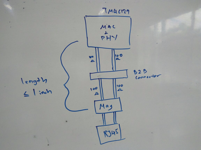
We have concern on differential pairs routing from the Magnetics+RJ45 (Magjack) to the B2B connector then to TM4C129x (PHY pins). 

1. use TM4C internal PHY – magjack is at motherboard

2. use ordinary MCU and place external PHY at motherboard

Detailed explanation as below.

We would like to know whether the configuration below will affect the Ethernet performance and produce interference?

or is it better to use an external PHY IC as shown in the picture below:

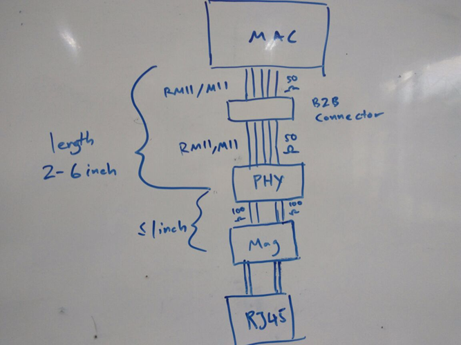
What we understand is that the RMII/MII signals are less susceptible to noise, and the routing of RMII/MII through the B2B connectors should cause less problems.

Please help to advise further.

  • TI has published guides that suggest keeping both interface traces short. I think in general, a short trace helps with reflections, and impedance doesn't need to be as strict if your trace is shorter than 1/10 the wavelength.

    Incognito said:
    the RMII/MII signals are less susceptible to noise

    That's the core assumption, but I would expect the PHY's  differential analog output to be more robust than the digital MII signal; even before the isolation magnetics.

    Side note, the MII spec calls for 68Ω. Is the chip's terminating impedance 50Ω?

  • Hi Peter,
    Thanks for providing your inputs.

    I think with the MII/RMII it is also critical on trace length matching as unmatched lengths may lead to timing issue. Too long of the trace can be susceptible to noise and crosstalk and increase EMI. I think the poster also needs to take into account overall BOM cost of adding external PHY and crystal unless the target is go 100Mb high speed. On the MDI differential signals, it is important to keep 100Ω differential impedance. I'm not sure if this can be achieved routing the signals through the B2B connector.

    Here are additional TI app notes on routing MDI differential signals and MII/RMII signals between the MAC and the PHY.
    www.ti.com/.../snla079d.pdf
    www.ti.com/.../spma056.pdf