


Tool/software: TI-RTOS
Hi,
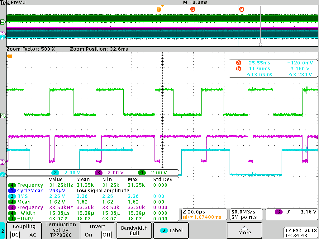
I am using MCU SPI to read from a slave device. Slave signalizes that is ready to provide the data by triggering my external interrupt. In the interrupt I post a semaphore to unlock the SPI_transmission. It was working ok when I was testing it with low bandwidth. At the end my slave triggers interrupt with 31.3kHz frequency, I need to read then 2 16bit frames. Once I operate with this frequency the delay between slave trigger signal and performing SPI task starts to be too big. In the external interrupt routine I just toggle a pin (just for reference) and post SPI semaphore. In the scope screenshot below the blue signal is a reference signal which should be toggled once code jumps to the drdy() routine, the green one is slave's trigger (falling edge is callign drdy().There is ~4us delay. The delay is even bigger when you look at the violet waveform which is one of the SPI's signal (slave enable signal).
I am using two tasks and one hwi. One task doesn't have while() loop and just runs at the begging to configure slaves(DAC_conf ()). The other task masterTaskFxn() is a SPI transmission task. I can see in the ROV that first task is terminated once it does the initialization. Then just the idle(), masterTaskFxn(), and hwi seem to be active. Is that significant delay a result of latency introduced by rtos scheduler itself or I can do better?
void hardware_init(void)
{

//    SysCtlPeripheralEnable(SYSCTL_PERIPH_GPIOB);
             // enable Timer 2
    //
    // Auxilaty SPI pins
    //
    GPIOPinTypeGPIOOutput(GPIO_PORTB_BASE, GPIO_PIN_5);  // Init PF4 as input
    GPIOPinWrite(GPIO_PORTB_BASE, GPIO_PIN_5,32);  // Init PF4 as input
    GPIOPinTypeGPIOOutput(GPIO_PORTB_BASE, GPIO_PIN_3);  // Init PF4 as input
    GPIOPinWrite(GPIO_PORTB_BASE, GPIO_PIN_3,8);  // Init PF4 as input
    GPIOPinTypeGPIOOutput(GPIO_PORTB_BASE, GPIO_PIN_2);  // Init PF4 as input
    GPIOPinWrite(GPIO_PORTB_BASE, GPIO_PIN_3,4);  // Init PF4 as input
}
/*
 *  ======== GPIO/DRDY HWI ========
 */
void drdy(unsigned int index)
//void drdy(void)
{
//    Semaphore_post(TCP_semaphore);
    GPIO_toggle(Board_TEST); // Init PF4 as input
    Semaphore_post(SPI_semaphore);

}

/*
 *  ======== SPI measurement transmission task ========
 */
Void masterTaskFxn (UArg arg0, UArg arg1)
{
    SPI_Handle masterSpi;
    SPI_Transaction masterTransaction;
    SPI_Params spiParams;
    bool transferOK;

    SPI_Params_init(&spiParams);
    spiParams.transferMode = SPI_MODE_BLOCKING;
    spiParams.transferTimeout = SPI_WAIT_FOREVER;
    spiParams.transferCallbackFxn = NULL;
    spiParams.mode = SPI_MASTER;
    spiParams.bitRate = 10000000;
    spiParams.dataSize = 16;
    spiParams.frameFormat=SPI_POL1_PHA1;

    Semaphore_pend(SPI_semaphore, BIOS_WAIT_FOREVER);

    /* Initialize SPI handle as default master */
//    masterSpi = SPI_open(0, &spiParams);
    masterSpi = SPI_open(Board_SPI0, &spiParams);
    masterTxBuffer2[0]=0b0001001000000000;
    masterTxBuffer2[1]=0b0000000000000000;
    masterTxBuffer[0]=0b00010010;

    /* Enable interrupts */
    GPIO_enableInt(Board_BUTTON0);

while(1)
{
    Semaphore_pend(SPI_semaphore, BIOS_WAIT_FOREVER);
    /* Initialize master SPI transaction structure */
    ctr1=ctr1+1;
    masterTransaction.count = 1; //Numbers of frames for a transaction
    masterTransaction.txBuf = (Ptr)masterTxBuffer;
    masterTransaction.rxBuf = (Ptr)masterRxBuffer;
    /* Initiate SPI transfer */
    transferOK = SPI_transfer(masterSpi, &masterTransaction);

//    if(transferOK) {
//        /* Print contents of master receive buffer */
//        System_printf("Master: %s\n", masterRxBuffer);
//    }
//    else {
//        System_printf("Unsuccessful master SPI transfer");
//    }
}

    /* Deinitialize SPI */
    SPI_close(masterSpi);

    System_printf("Done\n");

    System_flush();
}


/*
 *  ======== Config task ========
 */
Void DAC_conf (UArg arg0, UArg arg1)
{

    SPI_Handle masterSpi_dac;
    SPI_Transaction masterTransaction_dac;
    SPI_Transaction masterTransaction_s2p;
    SPI_Transaction masterTransaction_adc;
    SPI_Params spiParams_dac;
    bool transferOK;

    SPI_Params_init(&spiParams_dac);
    spiParams_dac.transferMode = SPI_MODE_BLOCKING;
    spiParams_dac.transferTimeout = SPI_WAIT_FOREVER;
    spiParams_dac.transferCallbackFxn = NULL;
    spiParams_dac.mode = SPI_MASTER;
    spiParams_dac.bitRate = 5000000;
    spiParams_dac.dataSize = 16;
    spiParams_dac.frameFormat=SPI_POL1_PHA1;

//            Semaphore_pend(SPI_semaphore_DAC, BIOS_WAIT_FOREVER);
            /* Initialize SPI handle as default master */
            masterSpi_dac = SPI_open(0, &spiParams_dac);
            //    masterSpi = SPI_open(Board_SPI0, NULL);

            /* Initialize master SPI transaction structure */
            masterTransaction_dac.count = 1; //Numbers of frames for a transaction
            masterTransaction_dac.txBuf = (Ptr)DAC_Buffer;
            masterTransaction_dac.rxBuf = (Ptr)masterRxBuffer;

            GPIOPinWrite(GPIO_PORTB_BASE,GPIO_INT_PIN_5,0);  // Init PF4 as input
            /* Initiate SPI transfer */
            transferOK = SPI_transfer(masterSpi_dac, &masterTransaction_dac);
            GPIOPinWrite(GPIO_PORTB_BASE,GPIO_INT_PIN_5,32); // Init PF4 as input
            DAC=1;

//            Semaphore_pend(SPI_semaphore_DAC, BIOS_WAIT_FOREVER);
            /* Initialize master SPI transaction structure */
            masterTransaction_s2p.count = 1; //Numbers of frames for a transaction
            masterTransaction_s2p.txBuf = (Ptr)S2P_Buffer;
            masterTransaction_s2p.rxBuf = (Ptr)masterRxBuffer;

            GPIOPinWrite(GPIO_PORTB_BASE,GPIO_INT_PIN_3,0);  // Init PF4 as input
            /* Initiate SPI transfer */
            transferOK = SPI_transfer(masterSpi_dac, &masterTransaction_s2p);
            GPIOPinWrite(GPIO_PORTB_BASE,GPIO_INT_PIN_3,8); // Init PF4 as input
            DAC=2;

//            Semaphore_pend(SPI_semaphore_DAC, BIOS_WAIT_FOREVER);
            GPIOPinConfigure(GPIO_PD2_SSI2FSS);
            GPIOPinTypeSSI(GPIO_PORTD_BASE, GPIO_PIN_0 | GPIO_PIN_1 |
                                            GPIO_PIN_2 | GPIO_PIN_3);

            masterTxBuffer[0]=0b0100000100000001;
            /* Initialize master SPI transaction structure */
            masterTransaction_adc.count = 1; //Numbers of frames for a transaction
            masterTransaction_adc.txBuf = (Ptr)masterTxBuffer;
            masterTransaction_adc.rxBuf = (Ptr)masterRxBuffer;
            transferOK = SPI_transfer(masterSpi_dac, &masterTransaction_adc);
            DAC=3;

//            Semaphore_pend(SPI_semaphore_DAC, BIOS_WAIT_FOREVER);
            masterTxBuffer[0]=0b00001000;
            /* Initialize master SPI transaction structure */
            masterTransaction_adc.count = 1; //Numbers of frames for a transaction
            masterTransaction_adc.txBuf = (Ptr)masterTxBuffer;
            masterTransaction_adc.rxBuf = (Ptr)masterRxBuffer;
            transferOK = SPI_transfer(masterSpi_dac, &masterTransaction_adc);
            DAC=4;

    /* Deinitialize SPI */
    SPI_close(masterSpi_dac);
    /* Open new SPI onnection that will send the measurements in a loop */
    Semaphore_post(SPI_semaphore);
    /* Enable interrupts */
    GPIO_enableInt(Board_BUTTON0);
//    GPIOIntEnable(GPIO_PORTB_BASE, GPIO_PIN_4);

    if(transferOK) {
        /* Print contents of master receive buffer */
        System_printf("Configuration done \n");
    }
    else {
        System_printf("Unsuccessful master SPI transfer");
    }
    System_flush();
}


/*
 *  ======== main ========
 */
int main(void)
{

    /* Construct BIOS objects */
    Task_Params taskParams2;
    Task_Params taskParams3;

    /* Call board init functions */
    Board_initGeneral();
    Board_initGPIO();
    Board_initSPI();
    SysCtlPeripheralEnable(SYSCTL_PERIPH_GPIOD);
    GPIOPinTypeGPIOOutput(GPIO_PORTD_BASE, GPIO_PIN_2);  // Init PF4 as input
    GPIOPinWrite(GPIO_PORTD_BASE, GPIO_PIN_2,4);  // Init PF4 as input

    hardware_init();

    /* install Button callback */
    GPIO_setCallback(Board_BUTTON0, drdy);

//    /* Enable interrupts */
//    GPIO_enableInt(Board_BUTTON0);


/* Construct master threads */
    Task_Params_init(&taskParams2);
    taskParams2.priority = 2;
    taskParams2.stackSize = TASKSTACKSIZE;
    taskParams2.stack = &task0Stack;
    Task_construct(&task0Struct, (Task_FuncPtr)masterTaskFxn, &taskParams2, NULL);
/* Construct master DAC Task threads */
    Task_Params_init(&taskParams3);
    taskParams3.priority = 1;
    taskParams3.stackSize = TASKSTACKSIZE;
    taskParams3.stack = &task1Stack;
    Task_construct(&task1Struct, (Task_FuncPtr)DAC_conf, &taskParams3, NULL);


    /* Start BIOS */
    BIOS_start();

    return (0);
}


