We are working on a project utilizing the USB PHY. We have been using the TM4C129-DK for our development and are now starting to run on our own custom hardware.
The custom board uses an external ST ULPI PHY but have been having problems with it (we do not have a breakout to test it with the TM4C129-DK). So we switched back over to just using the internal PHY on the custom board, but are still having the same results where the board essentially just does not respond.
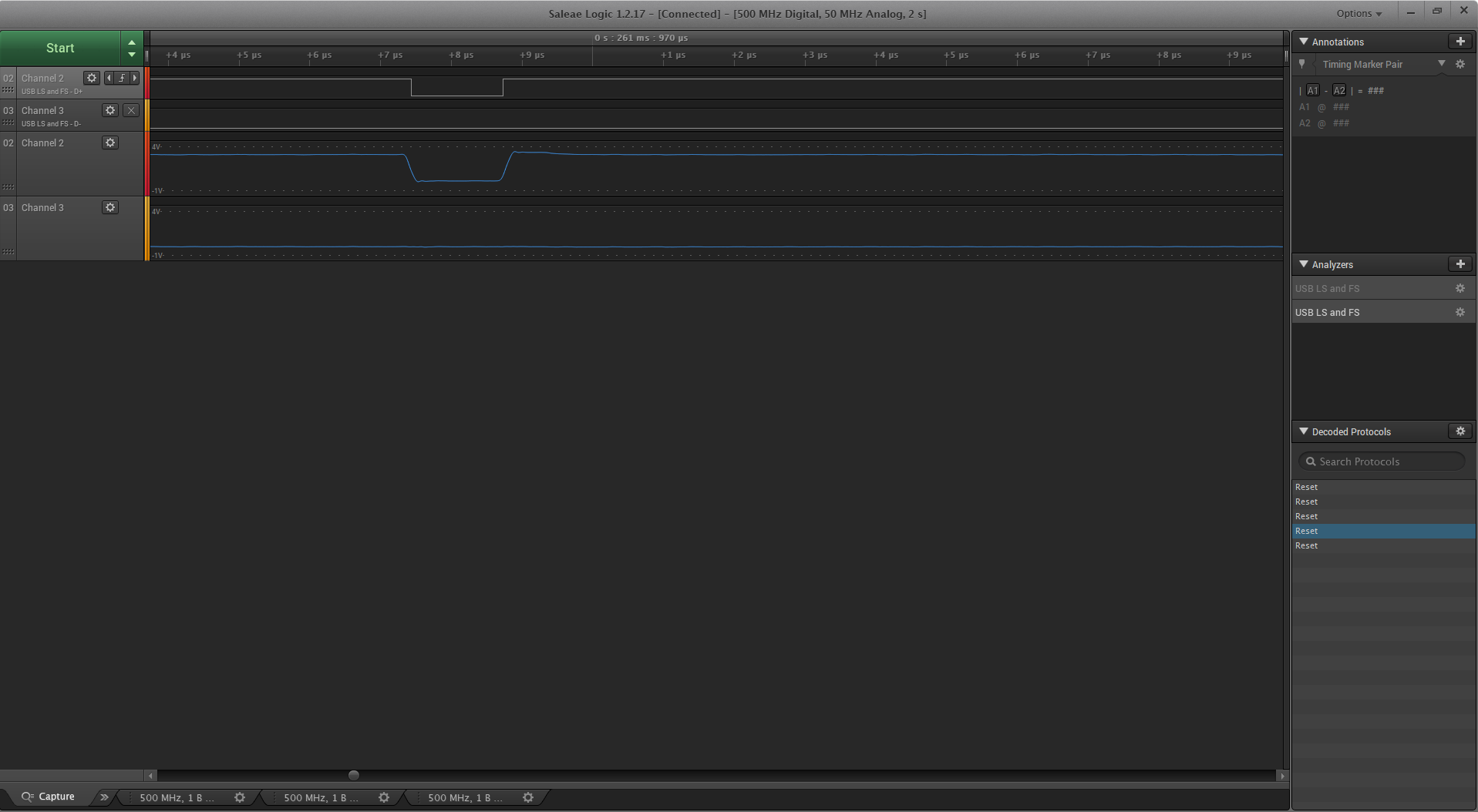
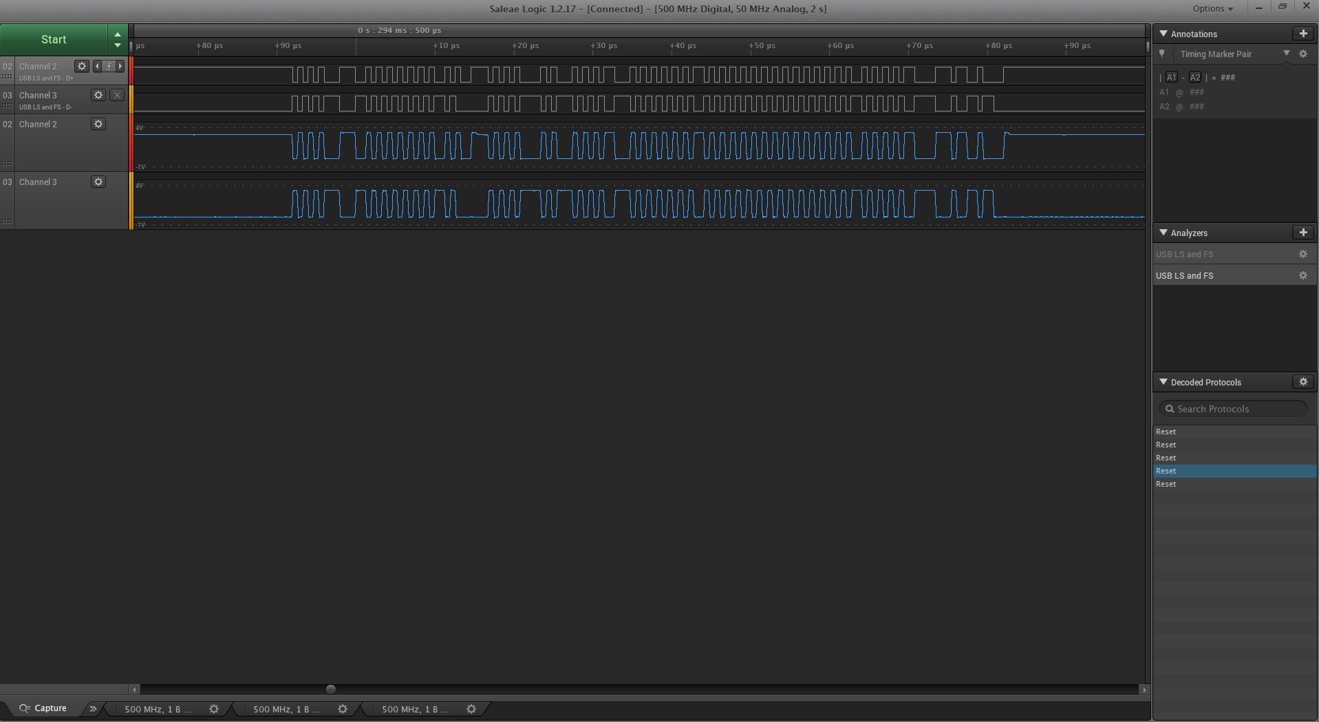
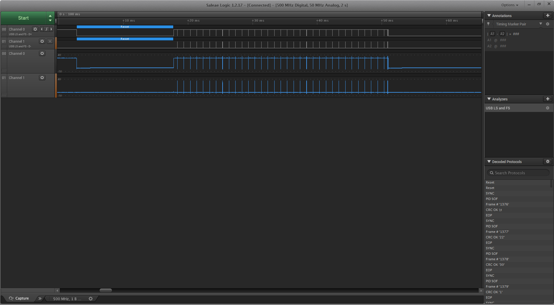
The USB startup code is the same as the start-up of the Bulk usb example provided in the Tivaware example. We are running the same code on the the DK as we are on our custom board, but get different results. I have attached some salae traces of the decoded USB messages.
What is confusing us is why the board does not respond, and when it does respond the analog traces look like digital traces (see attached traces). From what we can tell, there really is not much if at all anything that needs to be connected to the processor to get an internal PHY to work. It feels like there is just some simple and fundamental connection we are missing. We have also looked through the errata and did not see anything glaring at us.
To get some of the basics out of the way:
- There are no external resistors on D+ or D-. There is nothing in the between the processor connection and the USB cable connection. Diodes have been removed as well.
- USB Connections are hard connected
- Using the same setup on the DK as well as the custom hardware yielded the results.
- VBUS is not connected but we are using the "eUSBModeForceDevice" instead of "eUSBModeDevice" from the tivaware library
- This was verified by disconnected the VBUS jumper on J25 of the TM4C129-DK to "float" the pin as it is on our design
- VDDA and VREF are connected to the 3V rail
- Is there something else that generates the analog voltage for D+ or D- ?
- RBIAS is not connected (we are aware of the issues that causes in other places)
- The old stellaris required using the USBRBIAS pin, is there something for this device we are missing? The datasheet only mentions RBIAS for ethernet phy, not USB.
- Removed RBIAS from the DK as well and USB seems to be fine on the DK.
- The software is the same between both boards
- Tivaware 2.1.4.178
- Device Mode
- Full Speed
We can tell the processor is running by monitoring the JTAG port - everything looks OK and it does not shutoff/restart.
TM4C129-DK
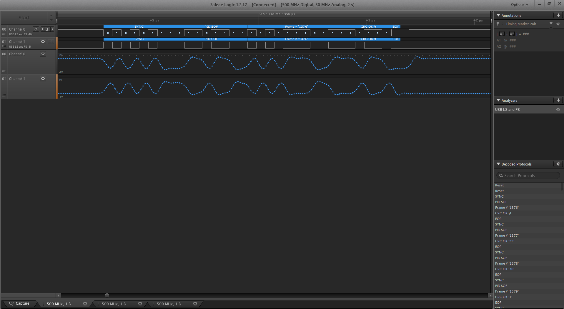
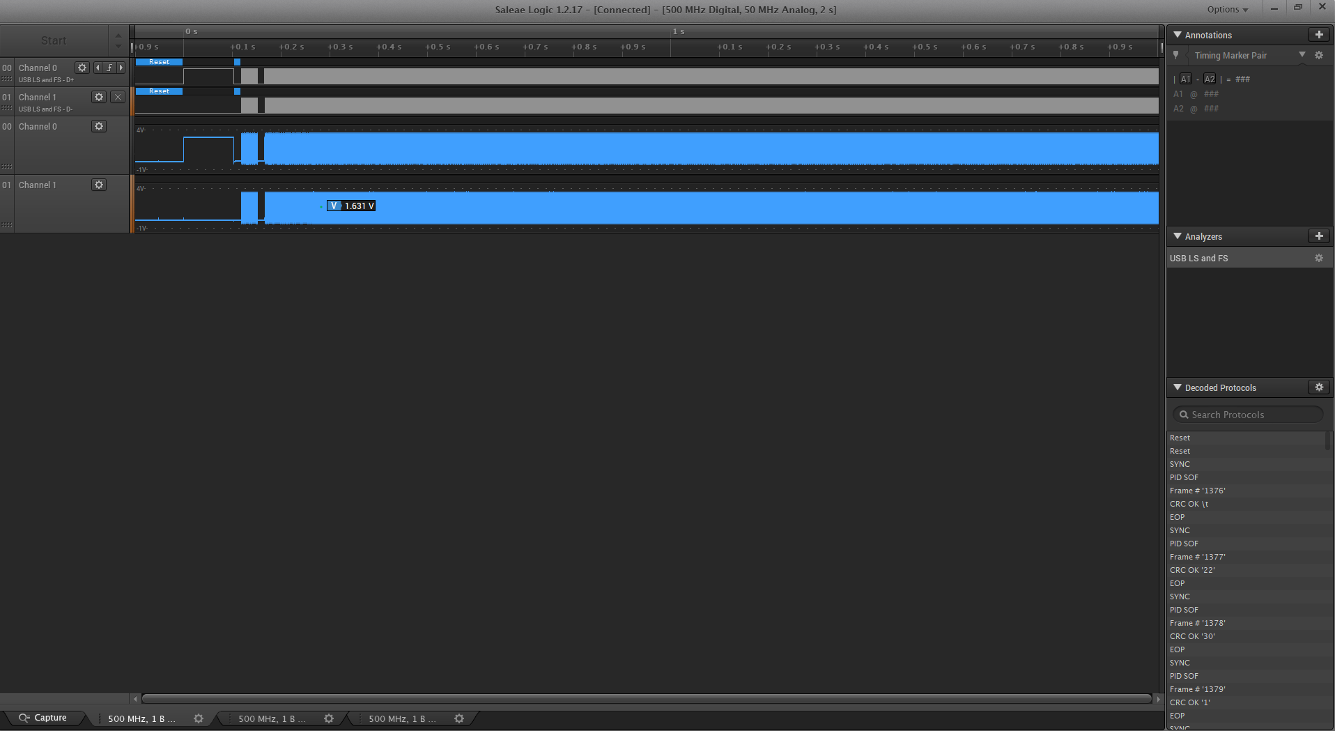
Custom Board