This thread has been locked.

If you have a related question, please click the "Ask a related question" button in the top right corner. The newly created question will be automatically linked to this question.

CCS/EK-TM4C123GXL: It does not follow the code correctly

Part Number: EK-TM4C123GXL
Other Parts Discussed in Thread: TM4C123GH6PM

Tool/software: Code Composer Studio

Hi,

I'm using ARM® Cortex®-M4F Based MCU TM4C123G LaunchPad™ Evaluation Kit, and I wrote a code to undestand better how TM4C123GH6PM and TIVA API works.

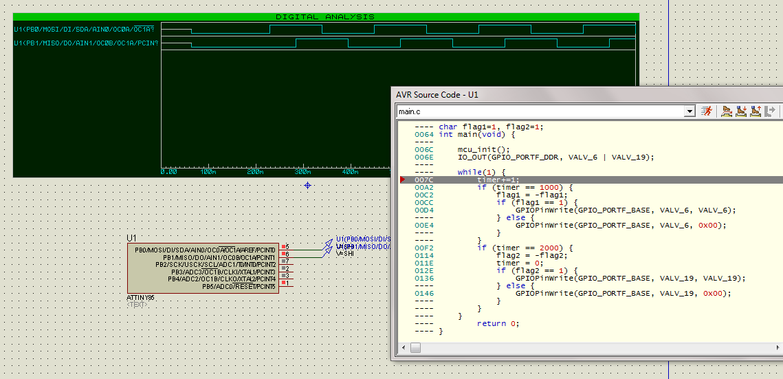
I imported the blinky code from resource explore and I modified it. When I debug the code, it doesn't work like I expected. PF_2 changes it's state every 20ms (like I was expecting), but PF_1 has a stranger behavior, it changes to high 10ms after PF_2 go to high, 20ms later it pulse to low and comeback to high and 20ms later it go to down. Same thing happens on the 'low' state of PF_2. 

I think that my code has an error, but I don't know if it's a problem on GPIO functions or something else.

The code:

/*
* PORT_A: PORT_B: PORT_C:
*
* VALV_3 PA_5 VALV_1 PB_0 VALV_11 PC_7
* VALV_4 PA_6 VALV_2 PB_1 VALV_13 PC_6
* VALV_5 PA_7 VALV_12 PB_6 VALV_15 PC_4
* VALV_7 PA_3 VALV_14 PB_7 VALV_16 PC_5
* VALV_8 PA_2 VALV_18 PB_3
* VALV_9 PA_6 VALV_20 PB_2
*
* PORT_F: PORT_D:
*
* VALV_6 PF_1 VALV_9 PD_6
* VALV_17 PF_3
* VALV_19 PF_2
*

*/

#include <stdint.h>
#include <stdbool.h>
#include "inc/hw_memmap.h"
#include "inc/hw_ints.h"
#include "driverlib/gpio.h"
#include "driverlib/sysctl.h"
#include "driverlib/timer.h"
#include "driverlib/interrupt.h"

#define VALV_1 GPIO_PIN_0
#define VALV_2 GPIO_PIN_1
#define VALV_3 GPIO_PIN_5
#define VALV_4 GPIO_PIN_6
#define VALV_5 GPIO_PIN_7
#define VALV_6 GPIO_PIN_1
#define VALV_7 GPIO_PIN_3
#define VALV_8 GPIO_PIN_2
#define VALV_9 GPIO_PIN_6
#define VALV_10 GPIO_PIN_4
#define VALV_11 GPIO_PIN_7
#define VALV_12 GPIO_PIN_6
#define VALV_13 GPIO_PIN_6
#define VALV_14 GPIO_PIN_7
#define VALV_15 GPIO_PIN_4
#define VALV_16 GPIO_PIN_5
#define VALV_17 GPIO_PIN_3
#define VALV_18 GPIO_PIN_3
#define VALV_19 GPIO_PIN_2
#define VALV_20 GPIO_PIN_2

#define VALV_A VALV_3|VALV_4|VALV_5|VALV_7|VALV_8|VALV_9
#define VALV_B VALV_1|VALV_2|VALV_12|VALV_14|VALV_18|VALV_20
#define VALV_C VALV_11|VALV_13|VALV_15|VALV_16
#define VALV_D VALV_9
#define VALV_F VALV_6|VALV_17|VALV_19

volatile int timer = 0;
volatile signed int flag1 = 1;
volatile signed int flag2 = 1;
volatile int32_t x;

void Timer0Isr(){
timer++;
TimerIntClear(TIMER0_BASE, TIMER_TIMA_TIMEOUT);
}

void TimerInit(){
SysCtlPeripheralEnable(SYSCTL_PERIPH_TIMER0);
while(!SysCtlPeripheralReady(SYSCTL_PERIPH_TIMER0)) {}

TimerConfigure (TIMER0_BASE,TIMER_CFG_PERIODIC);

TimerIntRegister(TIMER0_BASE, TIMER_A, Timer0Isr);
IntEnable (INT_TIMER0A);
TimerIntEnable(TIMER0_BASE, TIMER_TIMA_TIMEOUT);
IntPrioritySet(INT_TIMER0A, 0x00);

}

void GPIOInit(){

SysCtlPeripheralEnable(SYSCTL_PERIPH_GPIOA);
while(!SysCtlPeripheralReady(SYSCTL_PERIPH_GPIOA)){}

SysCtlPeripheralEnable(SYSCTL_PERIPH_GPIOB);
while(!SysCtlPeripheralReady(SYSCTL_PERIPH_GPIOB)){}

SysCtlPeripheralEnable(SYSCTL_PERIPH_GPIOC);
while(!SysCtlPeripheralReady(SYSCTL_PERIPH_GPIOC)){}

SysCtlPeripheralEnable(SYSCTL_PERIPH_GPIOD);
while(!SysCtlPeripheralReady(SYSCTL_PERIPH_GPIOD)){}

SysCtlPeripheralEnable(SYSCTL_PERIPH_GPIOF);
while(!SysCtlPeripheralReady(SYSCTL_PERIPH_GPIOF)){}

GPIOPinTypeGPIOOutput(GPIO_PORTA_BASE, VALV_A);
GPIOPinTypeGPIOOutput(GPIO_PORTB_BASE, VALV_B);
GPIOPinTypeGPIOOutput(GPIO_PORTC_BASE, VALV_C);
GPIOPinTypeGPIOOutput(GPIO_PORTD_BASE, VALV_D);
GPIOPinTypeGPIOOutput(GPIO_PORTF_BASE, VALV_F);

}


int main(void)
{

SysCtlClockSet(SYSCTL_SYSDIV_1 | SYSCTL_USE_OSC | SYSCTL_OSC_MAIN | SYSCTL_XTAL_16MHZ);
IntMasterEnable();

GPIOInit();
TimerInit();

TimerEnable (TIMER0_BASE, TIMER_A);
TimerLoadSet(TIMER0_BASE, TIMER_A, SysCtlClockGet() / 100000);

while(1){
if (timer == 1000){
flag1 = -flag1;
if (flag1 == 1){
GPIOPinWrite(GPIO_PORTF_BASE, VALV_6, VALV_6);}
else{
GPIOPinWrite(GPIO_PORTF_BASE, VALV_6, 0x00);}
}
if (timer == 2000){
flag2 = -flag2;
timer = 0;
if (flag2 == 1){
GPIOPinWrite(GPIO_PORTF_BASE, VALV_19, VALV_19);
}
else {
GPIOPinWrite(GPIO_PORTF_BASE, VALV_19, 0x00);}
}
}
}

  • Some recommendations:

    1. In main(), move the call to IntMasterEnable() to after all initialization, i.e., after GPIOInit(), TimerInit(), TimerEnable(), and TimerLoadSet(). This way interrupt service routines will not start being called until after everything is initialized.

    2. In Timer0Isr(), move the call to TimerIntClear() to the very beginning of the function.

    3. Conditions like "if (timer == 1000)" may be missed because timer is incremented in an interrupt asynchronously to the operation of main context. It may not occur now but if the program grows and becomes more complex, other operations happening in the main loop may cause you to miss these events. E.g., timer may be 999 when the processor executes this if statement; it may be 1001 the next time the processor executes this statement. Therefore you will not get the result you expect.

    The simplest way to handle item 3 is to check for timer == 1000 and timer == 2000 in the interrupt service routine. Because timer is incremented there, you will not miss the event. Then set a flag telling main context to do something. e.g.:

    ...
    
    
    volatile bool handle_flag1 = false;
    volatile bool handle_flag2 = false;
    
    
    void Timer0Isr(){
    	TimerIntClear(TIMER0_BASE, TIMER_TIMA_TIMEOUT);
    
    	timer++;
    	
    	switch (timer) {
    		case 1000:
    			handle_flag1 = true;
    			break;
    			
    		case 2000:
    			handle_flag2 = true;
    			timer = 0;
    			break;
    		
    		default:
    			break;
    	}
    }
    
    
    ...
    
    
    int main(void)
    {
    	SysCtlClockSet(SYSCTL_SYSDIV_1 | SYSCTL_USE_OSC | SYSCTL_OSC_MAIN | SYSCTL_XTAL_16MHZ);
    
    	GPIOInit();
    	TimerInit();
    
    	TimerEnable (TIMER0_BASE, TIMER_A);
    	TimerLoadSet(TIMER0_BASE, TIMER_A, SysCtlClockGet() / 100000);
    
    	IntMasterEnable();
    
    	while(1) {
    		if (handle_flag1) {
    			handle_flag1 = false;
    			
    			flag1 = -flag1;
    			if (flag1 == 1) {
    				GPIOPinWrite(GPIO_PORTF_BASE, VALV_6, VALV_6);
    			}
    			else {
    				GPIOPinWrite(GPIO_PORTF_BASE, VALV_6, 0x00);
    			}
    		}
    
    		if (handle_flag2) {
    			handle_flag2 = false;
    			
    			flag2 = -flag2;
    			if (flag2 == 1) {
    				GPIOPinWrite(GPIO_PORTF_BASE, VALV_19, VALV_19);
    			}
    			else {
    				GPIOPinWrite(GPIO_PORTF_BASE, VALV_19, 0x00);
    			}
    		}
    	}
    }
    

  • Your code is hard on the eyes.

    Maybe it is easier for you to state which kind of behavior you were expecting and which you are getting.

  • twelve12pm said:
    Conditions like "if (timer == 1000)" may be missed because timer is incremented in an interrupt asynchronously to the operation of main context.

    May we call, "Excellent?"      Especially as you've made the time/effort to describe, "How & Why" such (limited) a condition may be "missed."

    Another means to "Add Robustness" would be to employ,   "if (timer >= 1000)"  as this eliminates the (overly strict) "singularity of match!"           (such singularity - for what critical reason?)

  • cb1_mobile said:

    twelve12pm
    Conditions like "if (timer == 1000)" may be missed because timer is incremented in an interrupt asynchronously to the operation of main context.

    May we call, "Excellent?"      Especially as you've made the time/effort to describe, "How & Why" such (limited) a condition may be "missed."

    Another means to "Add Robustness" would be to employ,   "if (timer >= 1000)"  as this eliminates the (overly strict) "singularity of match!"           (such singularity - for what critical reason?)

    My initial thought was to use "if (timer >= 1000)" but there is a problem with that. From looking at the OP's code it appears the intended behavior is "edge-triggered" not "level-triggered." By asking "if (timer >= 1000)" one would service that condition up to 1000 times, until timer is reset back to 0.

    Timer is incremented only in the interrupt handler. It is not modified anywhere else. Therefore the interrupt handler cannot "miss" timer passing through the state of 1000 with a comparison of "==" -- UNLESS:

    Unless the programmer forgets that the correct operation of the program depends on timer never being modified anywhere else, and at some future time introduces code which makes such modification. Then, all bets are off. Therefore, to be much more certain that no other code will modify timer due to such a mistake, it can be made a static variable inside the interrupt handler function, so that no other code would have visibility to it. A comment to that effect would be helpful, too :-)

  • You've made a key/critical observation - I did not read that far into poster's code.

    That said - did he "really" require such "edge detection?" That in itself may signal, "less than thoughtful design - and as you neatly noted - opens "current & future code reviewers" - to disaster... (unless that code segment is properly - and notably - commented!)

  • cb1_mobile said:
    You've made a key/critical observation - I did not read that far into poster's code.

    That said - did he "really" require such "edge detection?" That in itself may signal, "less than thoughtful design - and as you neatly noted - opens "current & future code reviewers" - to disaster... (unless that code segmented is properly - and notably - commented!)

    I can't tell you how many times I've inadvertently caused "level triggered" behavior when I wanted to react to a transition just once.

  • twelve12pm said:
    ...many times I've inadvertently caused "level triggered" behavior when I wanted ..."edge triggered"

    You are correct, Sir.      That said - the use of the "forgiving test" (i.e. >=) may immediately, "Set some flag" - and thus accomplish the "twin goals" of (both) Code Robustness and "One Time (i.e. Edge) Execution."

    Many is the time we've encountered (and resolved) client issues - especially in "Noise Rich" environments - thru use of such "forgiving test."

    In addition - when such "forgiving test" is "hit" - cannot that event - "Clear and/or Re-Load" - the value being tested - insuring an "Edge Response?"

    Should one - for ANY reason - "miss" that "One and ONLY One" (overly critical) Test - you have "Booked First Class Passage - on the Titanic!" (water's STILL ... (very) cold/choppy - (ice infested) - we are told...)

  • cb1_mobile said:
    twelve12pm
    ...many times I've inadvertently caused "level triggered" behavior when I wanted ..."edge triggered"

    Agreed that that is more robust and I think worth the addition. That said twelve you deserve a like for your post. Quite agree with cb1 again on that aspect.

    Robert

  • as your code is poorly formatted, here is a reformatted while() loop - hopefully it will make your analysis a little bit easier:

        while(1) {
        	timer+=1;
            if (timer == 1000) {
                flag1 = -flag1;
                if (flag1 == 1) {
                    GPIOPinWrite(GPIO_PORTF_BASE, VALV_6, VALV_6);
                } else {
                    GPIOPinWrite(GPIO_PORTF_BASE, VALV_6, 0x00);
                }
            }
            if (timer == 2000) {
                flag2 = -flag2;
                timer = 0;
                if (flag2 == 1) {
                    GPIOPinWrite(GPIO_PORTF_BASE, VALV_19, VALV_19);
                } else {
                    GPIOPinWrite(GPIO_PORTF_BASE, VALV_19, 0x00);
                }
            }
        }
    

    an analysis of it is fairly easy.

    let's assume flag1=flag2=-1 at time 0/timer=0:

    time0/timer=0: flag1=-1/pin6=0, flag2=-1/pin19=0;

    time1000/timer=1000: flag1=1/pin6=1, flag2=-1/pin19=0;

    time2000/timer=0: flag1=1/pin6=1, flag2=1/pin19=1;

    time3000/timer=1000: flag1=-1/pin6=0, flag2=1/pin19=1;

    time4000/timer=0: flag1=-1/pin6=0, flag2=-1/pin19=0;

    ...

    so basically every 2000 counts on timer, pin6/19 are flipped (period = 4000 counts), except that pin6/19 are 90 degrees out (off by 1000 counts).

    a quick simulation on an avr showed the same results.

    now, I have no idea if that's what behavior you wanted - since you haven't told us. but if that's not what you observed, your problem is somewhere else.

  • Thanks guys for the replies!
    My interest is just that the pins have a period of 4000 counts and a delay one another of 1000 counts (only the state are of my interest), and that's just for me to remember how to use GPIO, interruption etc, there's really no use to it.
    Sorry for ugly code, the last time I programmed was 3 years ago and I couldn't copy the code indented.
  • Matheus Nogueira said:
    Thanks guys for the replies!
    My interest is just that the pins have a period of 4000 counts and a delay one another of 1000 counts (only the state are of my interest)

    In that case, forget about the main loop and marshalling "events" between the interrupt and main loop with volatile flags. Simplify the whole thing and do it all in the interrupt... Something like the following:

    void Timer0Isr()
    {
    	static uint32_t timer = 0;
    	static uint32_t state = 0;
    
    	TimerIntClear(TIMER0_BASE, TIMER_TIMA_TIMEOUT);
    
    	timer++;
    	if (timer >= 1000) {
    		timer = 0;
    
    		state++;
    		state &= 0x3;
    
    		switch (state) {
    			case 0:
    				GPIOPinWrite(GPIO_PORTF_BASE, VALV_6, 0x00);
    				GPIOPinWrite(GPIO_PORTF_BASE, VALV_19, 0x00);
    				break;
    
    			case 1:
    				GPIOPinWrite(GPIO_PORTF_BASE, VALV_6, VALV_6);
    				GPIOPinWrite(GPIO_PORTF_BASE, VALV_19, 0x00);
    				break;
    
    			case 2:
    				GPIOPinWrite(GPIO_PORTF_BASE, VALV_6, VALV_6);
    				GPIOPinWrite(GPIO_PORTF_BASE, VALV_19, VALV_19);
    				break;
    
    			case 3:
    				GPIOPinWrite(GPIO_PORTF_BASE, VALV_6, 0x00);
    				GPIOPinWrite(GPIO_PORTF_BASE, VALV_19, VALV_19);
    				break;
    		}
    	}
    }
    
    
    int main(void)
    {
    	SysCtlClockSet(SYSCTL_SYSDIV_1 | SYSCTL_USE_OSC | SYSCTL_OSC_MAIN | SYSCTL_XTAL_16MHZ);
    
    	GPIOInit();
    	TimerInit();
    
    	TimerEnable (TIMER0_BASE, TIMER_A);
    	TimerLoadSet(TIMER0_BASE, TIMER_A, SysCtlClockGet() / 100000);
    
    	// Start with these pins in state 0
    	GPIOPinWrite(GPIO_PORTF_BASE, VALV_6, 0x00);
    	GPIOPinWrite(GPIO_PORTF_BASE, VALV_19, 0x00);
    
    	IntMasterEnable();
    
    	while(1) {
    		// VALV_6 and VALV_19 are handled in Timer0 interrupt
    		// Possibly do other things here
    		// ...
    	}
    }
    

    Caveat: This is just an example to show what I'm talking about. I haven't actually tested this on hardware, but it will probably give something approaching the desired result. :-)

    This code incorporates the suggestions of cb1_mobile and Robert Adsett with respect to the "forgiving" ">=" test. It also makes the intent much more specific: that is, that we want to proceed through these four distinct states one after another in a circular fashion.

    Now if one wants to nitpick:

    * Strictly speaking, switch statements should have a "default" clause that performs some recovery from whatever inexplicable situation that causes the "state" variable to contain garbage. Since we are performing a bitwise AND with 0x3 in the line just before the switch, it is extremely unlikely that the default would ever be executed, because if "state" did contain garbage, it would now be garbage in the range of 0 to 3.

    * Someone will surely point out that my "timer" and "state" variables are not declared volatile. I declare them static inside the Timer0Isr() function, which means: (1) that their contents are preserved between calls and (2) that there is no visibility to these variables from outside Timer0Isr(). Because of said lack of visibility, no code should access these variables asynchronously to the interrupt. You must use volatile when there is asynchronous access from different contexts (main context, thread context, interrupt context). It tells the compiler optimizer not to get smart with that variable.

    If you really want extra credit, consider getting rid of the timer variable and test against 1000 entirely and set the timer's period to match the waveform you want. Then your interrupt would only increment "state," AND it with 0x3, and change pin states according to "state."

  • Nice job - hope our poster appreciates.    As to "extra credit" - crack staff note that such "credit" (even hallowed "extra") fails to satisfy (either) Canada's or Chicago's  "Power & Light."   (staff "expects" the pleasing, (incandescent) "over-head glow" - w/in our "back-room" - to continue...)

  • cb1_mobile said:

    Nice job - hope our poster appreciates.    As to "extra credit" - crack staff note that such "credit" (even hallowed "extra") fails to satisfy (either) Canada's or Chicago's  "Power & Light."   (staff "expects" the pleasing, (incandescent) "over-head glow" - w/in our "back-room" - to continue...)

    That's okay. In the submarine business, you get zero credit for diving. You only get points for coming back to the surface alive.

  • generating quadrature outputs can be done with timers / compare match. you can specify the phase difference and once set-up, it can be done without the cpu involvement, freeing it up to doing other things.

    here is an example: dannyelectronics.wordpress.com/.../

    the chip is different but the basic concept is the same.
  • And ... maintaining "lights on" - (even) while submerged - aids in that "surface recovery."
  • 
    

    "Something like the following:"

    you don't need that kind of complexity: you can do it in the main loop, and with timer count directly, like this:

      switch (timer) {
        case 1000: //do something with gpio
        case 2000: //do something with gpio
        case 3000: //do something with gpio
        case 4000: //do something with gpio
                   //reset timer
                   timer=0;
      }
    

    you can also put this in the isr but in my view much cleaner and a lot more readable to have it in the main loop.

  • Danny F said:


    "Something like the following:"

    you don't need that kind of complexity: you can do it in the main loop, and with timer count directly, like this:

      switch (timer) {
        case 1000: //do something with gpio
        case 2000: //do something with gpio
        case 3000: //do something with gpio
        case 4000: //do something with gpio
                   //reset timer
                   timer=0;
      }
    

    you can also put this in the isr but in my view much cleaner and a lot more readable to have it in the main loop.

    No.

    If you do that, then you will run into the problem where you might "miss" the timer equalling 1000, 2000, 3000, and 4000.

    It might not happen today. But tomorrow, additional code will be added to do other things, and that code will take longer to execute. You might execute your "switch (timer)" statement when timer is 999, then again when timer is 1001. The resulting waveform will be incorrect. This will all happen because timer changes asynchronously to execution of the main loop. If you do it in the interrupt, then it will work because timer increments synchronously to the "switch (timer)" statement.

    I agree with your earlier statement though:

    Danny F said:
    generating quadrature outputs can be done with timers / compare match. you can specify the phase difference and once set-up, it can be done without the cpu involvement, freeing it up to doing other things.

    here is an example: dannyelectronics.wordpress.com/.../

    the chip is different but the basic concept is the same.

    Waveforms should be generated by hardware peripherals if possible, because that results in a far more accurate waveform (better timing, less jitter) than one generated by software.

  • I generally resist the temptation to execute much in the isr.

    "You might execute your "switch (timer)" statement when timer is 999, then again when timer is 1001. "

    two ways to solve that:

    1) use flags in the isr and execute off the flags in the isr;
    2) increments in larger time duration. so rather than in 1ms (=1 count), as it is now, increments in 1s (=1000 count). so you lower the risk that you have a long task causing output jitter. in this case, your timer will go from 0->1->2->3->4/0->1...
  • Mes Amis,      Did we not  ALL - just hear this poor (and very) Dead Horse - "Cry for Quiet?"
    You've both done a great job - let's move onto some REAL issues.      (but not in "this" horse graveyard...)

    Note that this thread's "questionable" Subject/Title - almost guarantees that your continued efforts - will be "Little Reviewed."      And they deserve BETTER!

  • I read everything that you, guys, posted and it's realy helpful. I have never post nothing on TI's forum, so I don't know if everything that is useful for me should be marked "This resolved my issue". Well, if are you saying that the post should be closed, I agree, but I don't think that everything here will be "Little Reviewed" by me.

    Thanks!
  • As the thread's originator/author - you "are" likely to review it.

    Yet others - when "Searching for posts (somewhat) related to their (specific) needs" - are unlikely to "keyword in" anything near, "Does not follow the code correctly."     There's much of value here - yet the "Subject/Title" (as stated) dooms this thread to, "Low odds of Discovery."

    Over-Loading a thread - which is unlikely to be - "dialed up again" - seems not the best means to showcase "poster talent" - much in evidence here...

  • Nicely done twelve, the state machine is a good idea.

    Only one caveat, and I don't think we know enough here to know how to follow it in this case. Structure the state chart to follow the problem, not to follow coincidental timing. IE if you have two outputs that are notionally independent implement separate state machine for them even if the output changes coincide over some portion of the timing (even if that portion is all of it). This makes maintenance substantially easier.

    Something like Yakindu makes this kind of maintainence and documentation easier as well.

    twelve12pm said:
    Now if one wants to nitpick

    If you insist

    twelve12pm said:
    Strictly speaking, switch statements should have a "default" clause that performs some recovery from whatever inexplicable situation that causes the "state" variable to contain garbage.

    Yes and certain quality standards (such as MISRA and a number of security standards) make that mandatory. It's a good practice to get into and it costs you little. A good static analyzer will support this as well.

    twelve12pm said:
    Someone will surely point out that my "timer" and "state" variables are not declared volatile.

    Nope, there are two ways of using volatile incorrectly

    1. Not using it when it is needed
    2. Using it when it's not needed

    You don't appear to have committed either fault. Using volatile here would be a mistake, needlessly constraining the compiler.

    twelve12pm said:
    Because of said lack of visibility, no code should access these variables asynchronously to the interrupt

    That's really not the function of volatile. Its use in that situation is a byproduct of its guarantees, not a guarantee in and of itself.

     Robert