This thread has been locked.

If you have a related question, please click the "Ask a related question" button in the top right corner. The newly created question will be automatically linked to this question.

TM4C1294KCPDT: Tivaware USB0 Bulk device driver fails to transmit device descriptor packet to Windows

Guru 55913 points
Part Number: TM4C1294KCPDT
Other Parts Discussed in Thread: EK-TM4C1294XL, , TM4C1294NCPDT, TPD4S012, TPS2051B, TPS2052B, TPS2051

Same Bulk Device driver software configuration loaded on  EK-TM4C1294XL and Windows device client makes a connection with USB0 via the  OTG port .

All connections USB0 out to micro USB port (OTG) to a custom PCB ring out typical of launch pad OTG port.  Debug USB0 FIFO's are counting and toggle VBUS power CTRL REG bit when USB cable is plugged or unplugged. Yet no connection to target via any of four bulk device client addresses (typical 0x0-0x3) can be established

The only (documented) difference between each type of MCU is the flash memory is 512KB (TM4C1294KCPDT) versus 1Meg TM4C1294NCPDT.

Any idea why USB0 of KCPDT MCU is behaving differently than TM4C1294NCPDT?

  • Hello BP101,

    There aren't any differences between USB for those two devices that I can see. Are both the KCPDT and NCPDT used on the exact same hardware and using the exact same software but are demonstrating differing behavior? It sounded like you are using two different boards?

    I may be not following your post clearly but my understanding of the setup is:

    Same USK bulk software is on:
    1) EK-TM4C1294XL w/ TM4C1294NCPDT
    2) Custom PCB w/ TM4C1294KCPDT and USB layout per design guidelines

    Or am I misunderstanding the hardware setup?

    Do you have any information on what packets are being transmitted when the failure occurs? Are there any USB EVENT's being reported then?
  • Hi Ralph,

    Exactly 1 & 2 Is the same SW with different variant for custom PCB. USB0 is not detected by Windows or target is not transmitting a USB descriptor to host upon USB0 VBUS pin going high.

    Normally Windows 7 informs when the bulk device USB port is first plugged in only if there are no cached connections. Device manager does not show the USB target connection hidden or otherwise when target USB is plugged into host.
  • Everything is the same other than UART3 custom PCB was UART0, PWM0 GEN0 custom was GEN1 on EK129XL. Also ENLED-0/2 are now PK4/5 so PWM0 GEN0 can use PF1/2 pins. Seems to me some MUX issues may be happening in Tivaware!
  • Hello BP101,

    I haven't been able to come across anything which would indicate a problem based on your description thus far. Given the issue is occurring on a custom PCB, I think what needs to be checked is the hardware setup and ensure that correct packets are being sent/received with a USB analyzer. Alternatively you may be able to debug the USB communication with breakpoints to verify packets are being sent/received correctly. If so, then you should be able to track down what state the USB library is in and what packet causes the failure, and from there I would have a better chance to be able to offer advice on how to solve the issue.
  • Along w/Vendor Ralph's sage advice - would it not prove useful to, "Properly probe the USB_0's MCU pins" - to insure that MCU's USB Output does occur - AND that PC's USB Output reaches the appropriate MCU pins?     We note your claim, "ring out typical of launch pad OTG port" - yet that's sufficiently vague as to require clarification.     As always - what IS "typical?"

    As yours is a "brand new board" - is not EVERYTHING SUSPECT?      Firm/my preference would be to, "Start your check via scope-monitoring of the MCU's USB pins - and then progressing (if the signals DO appear @ MCU) to the board's USB connector.

    "LOS" (Loss of Signal) anywhere along the line - will produce the "dead communications" issue  you note...

    Most always - my group finds it more efficient to perform,  "Basic exercise of the hardware" - prior to (any) deep-dive into the software...     Of course you must properly,  "Set-Up & Config." the Peripheral - prior to any, "Test/Verify" of the hardware...

    Just as in your posted issue here yesterday (linked below) - which my group successfully diagnosed & resolved - the excitement & demands imposed by a new board - may have (again caused) a faulty parameter - or improper "Peripheral Set-Up/Config" - and those vital code bits have not been presented for "skilled" review, here...

    https://e2e.ti.com/support/microcontrollers/tiva_arm/f/908/t/669222

  • Hi Ralph,

    The TI USB VID is not being sent in the USB0 Descriptor packet makes one question does USER0/1 registers need to programmed with VID much like a MAC. Perhaps that VID is being flashed in the factory loaded firmware of the launch pad?
    Two Windows computers acknowledge USB connection as Unknown device and assigns a generic VID and the composite driver is never installed. The TXFIFO stops counting yet the proper interrupts get set.

    If you don't believe the MCU has USB port issues perhaps remove TM4C1294NCPDT from EK-TM4C1294XL and install TM4C1294KCPDT witness the results. All I know is plugging in the USB cable to a hub has twice caused MCU POR and later over temperature occurs for no good reasons. The MCU pins out to the USB port are not crossed and do not have high resistance shorts even in the pads of 4 channel ESD protector TPD4S012. Has anyone ever tested TM4C1294KCPDT MCU in a launch pad?

  • TM4C1294KCPDT MCU's are on backorder?

  • Feel your pain - sorry to learn of your issue.      And ... "Where is Peter Sellers (Inspector Clouseau) when we need him?"

    As you, "Question your chosen MCU" and "as it appears No Longer available" - does it not prove best to install the larger capacity device?       (assuming the pin-out & key power/signal pins ARE compatible.)

    Should your issue continue - the venom aimed @ the "twice failed MCU" - may be unfair.       Suggestion herein advanced seems, "shortest path to the "clear identification" of your "KCPDT" as issue's cause."

  • Hello BP101,

    Regarding the device availability, the device isn't being made unavailable because of issues or any plans to EOL it - there are no such plans for any TM4C device including the KCPDT version. The issue you are seeing is most likely that we must not have available stock to ship out currently from the eStore. Happens from time to time, especially for devices with significant demand. Digikey or Mouser may have immediate stock for samples?

    Regarding this specific MCU having USB issues, I am not sure where you are getting this idea from with your experience on our forums. You've even answered questions in the past about TM4C1294KCPDT USB functionality. Many other users have used USB without an issue with this device as well. I am more than willing to try and help give advice for debug, but I would ask you please to consider that the issue may reside within your custom PCB and not that you've discovered an MCU flaw unseen by many others who used it for USB functionality with success for years.

    Now then, regarding the VID, that is not stored/committed in Flash memory beforehand like is the case for Ethernet MAC Address. The VID is defined by USB_VID_TI_1CBE in the usb-ids.h file within our usblib. That value is then used within each of our USB examples as part of the usb_structs.c file (also named as usb_bulk_structs.c, usb_serial_structs, etc. based on example) to create the structures used for device initialization.

    BP101 said:
    Has anyone ever tested TM4C1294KCPDT MCU in a launch pad?

    Have you? Is there a problem on the LaunchPad with the swapped device? We have too many devices to just go and test them all on our LaunchPad even if this case just differs in Flash size.

  • Redacted the out of stock meme...

    Ralph Jacobi said:
    I am more than willing to try and help give advice for debug, but I would ask you please to consider that the issue may reside within your custom PCB and not that you've discovered an MCU flaw unseen by many others who used it for USB functionality with success for years

    Actually the same issue is occurring in the EK-TM4C1294XL from my investigation yesterday. However the EK's OTG port is not being totally degraded, VBUS pin (PB1) is partially shorted to ground on several that still work but the MCU temp (may) rise 60*C or higher very quickly on some. A few launch pads have been effected after plugging the OTG port into an 8 port USB hub, powered from host computers USB port VBUS power through the hub. Personally witnessed several POR events last 3 years and didn't think was an issue until several EK started to over heat MCU for no apparent reason, unaware PB1 was being degraded. A good (PB1) measures over 100k ohms to ground (unpowered), a marginal USB0 VBUS (PB1) measures 39-69 ohms. Other devices plugged into same USB hub never seem to have an issue of POR and a few are self powered which infers wall power in my book since the host does not supply +5 VBUS to the OTG device. That term (self powered / bus powered) device seems a bit confused in TM4C1294 datasheet & design guide, are not being fully qualified the host infers (target) at times is hosting OTG port.

    What if the OTG bulk device is connected to a host computer used for bulk transfers to a Windows bulk device client, is that considered a self powered device or bus powered? The USB library seems to think (self powered) device is proper in that case as debug indicates VBUS power bit toggles high to the USB cable insertion to 8 port hub at least until it has been rendered ineffective by the voltage/current surge.  

    What was occurring after plugging in USB cable to OTG port sometimes might POR the launch pad, powered via host computer ICDI (JP1). Custom PCB uses 5v switcher driving 3v3 LDO to supply the USB0 peripheral thus drawing excessive current out PB1 after an unexpected POR occurs a (few times), 3v3 LDO gets very hot. It would seem EK-TM4C1294XL USB0 OTG port ESD protection device TPD4S012 is not clamping VBUS surge voltage below 5v5. Seemingly an anomaly shorts out PB1 after few times OTG has unexpected POR, EK or custom PCB. That is what damages the USB0 peripheral and the FIFO stops transmitting the data to the device. It seems we have an engineering flaw that perhaps a Schottky diode series with PB1 can resolve or a lower voltage VBUS clamp may be better suited to correct?

    4.3.3 USB OTG:
    TM4C129x devices that support USB OTG mode include the signals for USB Device mode, signals for
    USB Host mode and an additional signal USB0ID located on pin PB0. This USB ID signal is the 5th 4th pin
    found on a USB micro-AB connector. If a micro-A cable end is plugged into this connector, the ID pin on
    the cable is tied to ground causing the TM4C129x device to operate as a USB host. If a micro-B cable end
    is plugged into the USB connector, the ID pin is left floating. In this case, the TM4C129x device's internal
    pull-up on the USB0ID signal causes the controller to operate in device mode.

    In order to limit damage from ESD events, a 100Ω resistor should be placed in series between the ID pin
    on the USB connector and USB0ID(PB0) on the microcontroller.

    To support full USB OTG negotiation using the SRP and HNP protocols, VBUS from the USB connector
    must be directly connected to USB0VBUS(PB1) of the microcontroller without a series resistor in between.
    In this case, USB0VBUS should be connected to an ESD suppressor such as a TVS diode, or ESD
    resistant VBUS switch.

  • Hello BP101,

    I have tried to re-create this issue on the EK-TM4C1294XL and have not had any success. Using the usb_dev_bulk example from TivaWare, powering the LaunchPad with ICDI, and then unplugging and replugging the cable for the Target USB connection, I have never created a POR. I tried at least 50 times at varying intervals from sudden disconnect/reconnects to delayed attempts. Not a single POR issue, which aligns with the experience I've had working with the LaunchPad daily for many months now running many many different examples... never had unexplained POR for anything, ever (I picked out my daily use LaunchPad for the above tests too by the way, the one that would have seen the most 'wear and tear' of circuitry).

    Have you ever experienced this behavior without the 8 port hub? What if a new LaunchPad is plugged directly into your PC with no hub? Same questions for the custom board which exhibited issues as well, have you ever had a new custom board (not plugged into possibly damaging hub) plugged straight into your PC? Any issues in that case?

    It's fine to know other devices don't have an issue with this particular hub, but as I am not able to replicate the behavior here, I strongly suspect your USB hub is the cause here, especially given the behavior described sounds like something (the hub) is sourcing the LaunchPad with more juice than it is meant to handle under normal circumstances.

    By the way, self-powered vs bus powered is an application specific setting. Our TivaWare example uses USB_CONF_ATTR_SELF_PWR, but you can change that how you wish.
  • cb1_mobile said:
    As you, "Question your chosen MCU" and "as it appears No Longer available" - does it not prove best to install the larger capacity device?

    Is the above - STILL - not the, "Fastest & most direct means" to discover if your "chosen MCU"  (really)  suffers such weakness?

    You've asked that Vendor implement this - yet that fails for these reasons:

    • You've reported that your MCU - for whatever reason - appears not readily available.    How then - can the vendor perform such (swap MCUs) test?
    • Your custom board is brand new - that alone makes it  "highly suspect."
    • Should the issue continue when you switch to the LPad's/Eval Board's MCU - then your "chosen MCU" likely has,  "Escaped BLAME!"

    It is hoped that the LPad's MCU proves direct:  "form/fit/function/pin-out" replacement  - for your "chosen" one!

  • Hi Ralph,

    Ralph Jacobi said:
    I have tried to re-create this issue on the EK-TM4C1294XL and have not had any success

    It is a slow degrading process on the EK-TM4C1294XL so that plug unplug method is futile at best. Testing the OTG port VBUS pin resistance on a few boards hanging around is a good way to be come aware if something is attack the 5v tolerant PB1 silicon or not. Measuring resistance PB1 under 100k is a sign the pin has been degraded, yet I have one here measures 39 ohms and is working ok MCU temp 49*C @70.8*F ambient. One MCU USB0 PB1 measured 69 ohms on the PCB (locked frame counter) the 3v3 LDO was getting burn finger tip hot but a new MCU was fine until the POR of USB port. 

    Ralph Jacobi said:
    replugging the cable for the Target USB connection

    . Agree the sub miniature USB plugged into OTG on target never seems to cause this issue or it is not driving a POR. 

    Ralph Jacobi said:
    Have you ever experienced this behavior without the 8 port hub?

    Yes the larger USB plugged into port of hub more often yet computer USB port though rare, POR events on OTG have occurred before I got the hub. The point is how damaging to (PB1) as the MCU didn't POR for no reason. Seem to recall others in this forum have mention POR issue in past. This is a fairly new hub and there is no bypass on the VBUS pin of target when a TPS4051/52 VBUS switch is not installed. There are pads for VBUS power sourced via a ferrite bead leading to bypass caps of TPS4051BD when USB0 is in OTG host mode, are now  DNP. There are no bypass caps discussed for VBUS in the TMC4129x designer guide text but do see pads just off the OTG pin 1 for a large cap to ground before the TPS power VBUS switch. The USB 8 port hub design should have a 22uf or higher on VBUS pin 1 for each port to help absorb the current spike during a plug in. Not sure why or what is going on in that connection but it shouldn't load down PB1.

    If you research the ESD device that is supposed to protect VBUS pin PB1 from ESD, overvoltage on VBUS  it is perhaps failing to do that. I have opened a post in another TI forum for the TPD4S012 having very high clamping 13.5v-15v where other VBUS TVS diodes clamp at a much lower voltage 7.5v. It could be excessive pin current on PB1 another possibility but what has caused it twice on two MCU's. 

  • BP101 said:
    more zero clean flux plus 10 seconds of hot air 245*C

    There have been reports of such,  "Hot Air" devices - generating ESD!      Would prove wise to check your device's specs for, "Notice that ESD Safeguards are "IN PLACE."    I'd call the maker as well - should the "3 prong plug" have been "converted" to 2 pin - voila!

    I would STILL ... ... Change the MCU to that used by the LPad/Eval Board - whichever you past used w/Success!

  • Hello BP101,

    So the issue is not when the plug in occurs, but rather if the LaunchPad is left sitting, it will POR? How long do you think they've been powered for? I ask because I have my own LaunchPad plugged in all the time and never have had any issues, and it's been used and abused heavily over the course of at least 6+ months. How long have those custom boards existed? It sounded like they were pretty new... if it's damaging over time, what is the time frame this stated 'damage' has taken place?

    In any case, I am not seeing any possible way for us to try and recreate this to be able to offer feedback or support based on your descriptions thus far...
  • Ralph Jacobi said:
    What if a new LaunchPad is plugged directly into your PC with no hub? Same questions for the custom board which exhibited issues as well, have you ever had a new custom board (not plugged into possibly damaging hub) plugged straight into your PC? Any issues in that case?

    The custom PCB after replacing 1st MCU was first plugged into computer USB port when a popup message stated an unknown device was plugged into the system. Was already in CCS debug via XDS100v2 and USB0 frame counter was stuck on some odd number, FIFO0 count not moving yet all others were counting.

    Later next day unplugged from computer and tired two different USB hub ports resetting MCU between each port move to get a TX packet descriptor to trigger. Actually caused POR very next day after 1st checking all micro USB plug pin connection into MCU were spot on.  

  • If you read carefully it is an ongoing issue no matter how the OTG port is being plugged in.

    You have yet to explain how the ESD suppressor clamping zener voltage for VBUS may not be proper to begin with for this MCU. I highly question the zener diode clamping voltage for (VBUS) being 20v 13v-15v can ever do any good to protect a 5 volt tolerant MCU pin.

  • If interest link below and don't for get DMM resistance test TP4 to ground on several EK OTG ports. It could be the two MCU USB0 were marginal to begin with, 4 new ones were sourced from Mouser.

    https://e2e.ti.com/support/interface/circuit-protection/f/389/p/670553/2466803#2466803

  • Station is very nice PID controlled hot air and iron have digital readouts, 3 leg plug. Will check the hot air tip to see if it is grounded too.

    Opened up USB hub, not one single electrolytic on the VBUS line yet holes near most ports existed. Plated holes for 5 caps, added 2-47uf/2-10uf/1-0.1uf on the VBUS rail & DC supply jack. Noticed all the metal jack shields connected to DC ground not a separate frame ground and jack pins were simply dog eared over bottom side, not even soldered. Soldered ears trimming extra long pins off and gave the entire hub a twice over visual inspection. So DC ground is common with shield ground inside the USB hub but not on the PCB which has a perimeter frame ground ESD static discharge path for the micro mini plug sheild.

    Computer has 2 front USB ports metal shields are at frame grounded, same way on the PCB micro mini port. Don't think that could cause issue but do have 150mohm ferrite chip on USB pin 5 into digital ground. The MPU is pulling roughly 200ma with very few peripherals enabled only after the 2nd POR event plugging into hub. Don't think USB port ground pin ferrite may be causing any issue since TI used ferrite beads on a USB hub schematic to filter ground noise on each ports ground pin 5. May reduce the ferrite resistance to 75mohm for good measure and later 50mohm.  

  • Thank you - that's quite a detailed (and valuable) write-up.     Note that I reply as firm/I  "Feel your pain" - yet as famed author Don Lancaster - long ago advised - "Blame yourself FIRST - the IC (MCU, here) ALWAYS LAST."

    I continue in the belief that  your (by FAR) best INSIGHT into your recent, "TWO infant MCU failings" - springs from your replacing your chosen MCU w/that MCU (very successfully PROVEN) on vendor's Eval/LPad boards.     Should the addition of that "Eval/LPad MCU" prove successful - then your report of  "MCU difficulty" (experienced upon your chosen/different MCU) - may gain  FAR MORE credence!

    Do accept that any new board design is - most always - HIGHLY SUSPECT.     I imagine that even (this vendor) went through (several) board spins - prior to being satisfied.

    Now consider this - in regards to your reported, "TEN SECONDS of "Hot Air Stream" - directed @ your chosen MCU - while soldering.      As there was, (likely) "NO Applied Voltage CONNECTION to your ESD chip's (TPD4S012) "V_Bus" pin - while soldering - has not the, "hoped for ESD protection" - been compromised?    (DURING that "HOT-AIR" - Soldering Bombardment!)

    A past IEEE paper (staff programmer here recalls) reported upon, "Heated & Propelled, Ionized Air" - having the potential to generate, "Electro-Static Voltages."      My firm can neither "confirm nor deny" - our "bought at auction" - then rebuilt - 20 foot - multi-stage, Reflow Oven - notes its, several, "counter-measures" - AGAINST such  ESD!

    I suggest - at least while the "MCU as suspect" lingers - that you have an "Eval/LPad MCU" installed by a proven, "Board Assembly House!"      And only then - relaunch your board test...

    As always - and especially as "banned here" - this method embodies "KISS" - which  "sensitizes one" to the,  "Requirement to LIMIT the number of (potentially) Impacting VARIABLES!"

  • To strengthen the case of your,  "Hot-Air Tool" - possibly serving as an unwanted, ESD source - I present this catalog page from "Steinel" - a "Hot-Air Tool" vendor.     Tonight's reasonable survey - reveals that, "Less than 20% of such tools" - are judged/listed as,  "ESD Safe!"      This percentage of, "Hot-Air - ESD-Safe" tools held across 2 additional vendors...

    In light of this finding - the suggestion to have an  "LPad/Eval Board MCU" (rather than the MCU you believe "flawed") soldered by a, "Skilled (well equipped) Assembly house" - makes great sense...

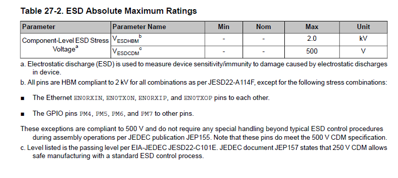
  • Does not that ESD shift simply ignore several writings stating VBUS pin was compromised during plugging it into the USB hub, not just one time but only after several plugging did it ever fail. And the TM4C1294x MCU is HBM compliant to 2Kv for ESD stresses most package pins,  note (c) standard 250v control process during assembly. That is 2Kv free air static discharges mostly for shipping & handling before MCU is placed on top of copper pads. Once the chip is mounted or even sitting on top of solder pads the chance of ESD damaging the MCU is greatly reduced.

    From our perspective it seems you have not considered the ramifications of chosen ESD devices (claimed) ability to properly protect 5 volt tolerant current path into the MCU via pin PB1, nor did the vendor. Is not that alone the most likely and obvious suspect as the only pin DMM measures very low 69 ohms, when other USB port pins do not. Could it be the potential difference between system grounds (absent any transient filters) suddenly caused current flow out pin PB1 in excess of 64ma, the absolute maximum allowed any GPIO pin. Do you not suspect 150mohm ferrite chip added on pin 5 (digital GND) may actually rise 5v level of PB1 exacerbating conditions during a voltage/current surge. The drop across the 175mohm ferrite will rise as the current through it does too (R=E/I) in an (uncontrolled) voltage overshot.

    Who even knows what the maximum 5v tolerant conditions of PB1 are being TM4C1294 datasheet makes no claims of having any robustness at all, could be 5v5 but who really knows for sure. Yet pin PB1 is freely exposed RAW to voltage overshot above 5v leaves one questioning all modes of attack upon it. Secondly the TPD4S012 TI placed on EK-XL launch pad does absolutely nothing to stop sudden voltage rise upon PB1 unless ESD caused it and only then at an DC voltage overshoot condition near 13.5v. 

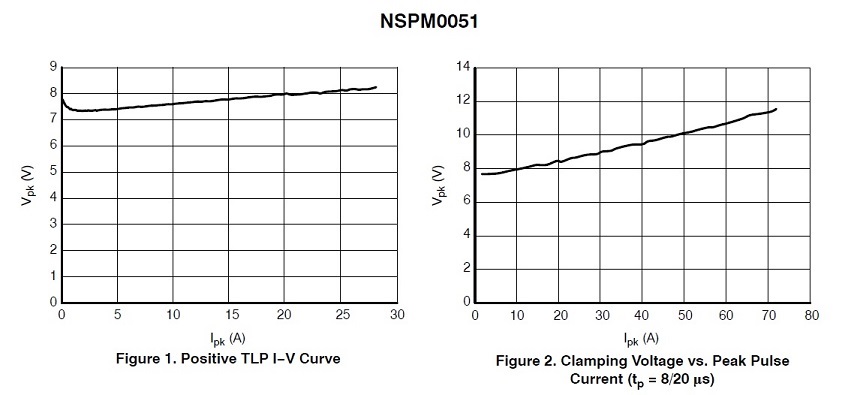
    Problem determination focus should remain on the 5v tolerant PB1 MCU pin and the circuitry around it being highly suspect for both boards (EX-XL/Custom). A lower clamping voltage zener will be placed on VBUS pin to stop undesired plugging surges. OnSemi NSPM0051 specifically designed for protecting VBUS pin from +/-30KV ESD spikes has reverse working voltage (VRWM 5v), test case data clamps voltages 7.5v @1amp 8*20us pulses (VBR 6-9v) figure 2.  

  • BP101 said:
    Problem determination focus should remain on the 5v tolerant PB1 MCU pin and the circuitry around it

    Or not!      Taking "one last whack" at this dead/dying horse - as you've "challenged" vendor's (non-Eval/LPad) MCU - your (proper, ESD Safe) replacement with a fresh "Eval/LPad MCU" INSTEAD -  will  quickly & easily,  "Remove your chosen MCU" from the "suspect list."    (while providing further insight as to your custom board's implementation success.)   

    Is it possible that you've "missed" - or under-valued - the (usual) ESD "8/20µS" pulse  "RESTRICTION" - provided by  "usual"  ESD protection components.      You reported a, TEN SECOND, "Hot-Air" Soldering interlude - directed fully at your (non-Eval/LPad) MCU  - which (somewhat) exceeded the normal/customary 8/20µS ESD impulses - reflected w/in (most all such)  "multi-vendor" - ESD resistant curves...

  • cb1_mobile said:
    Or not!      Taking "one last whack" at this dead/dying horse - as you've "challenged" vendor's (non-Eval/LPad) MCU - your (proper, ESD Safe) replacement with a fresh "Eval/LPad MCU" INSTEAD -  will  quickly & easily,  "Remove your chosen MCU" from the "suspect list.

    Yet several launch pads VBUS lines have been (slowly) degraded from plugging into a questionable hub design. Patiently wait for vendors report of DMM testing several TP4 resistance for any suggested WA to limit voltage/current surges upon VBUS signal line PB1. There are USB hub design rules (ALL) vendors must follow and clearly some imports into US attempt to skirt proper VBUS design rules for Host/Self-powered/Bus-powered Hubs. If truly interested and desire to learn proper USB device connections, basic VBUS power discussion starts page 20: TPS2051B, TPS2052B.

    cb1_mobile said:
    You reported a, TEN SECOND, "Hot-Air" Soldering interlude - directed fully at your (non-Eval/LPad) MCU  - which (somewhat) exceeded the normal/customary 8/20µS ESD impulses - reflected w/in (most all such)  "multi-vendor" - ESD resistant curves...

    That is just silly to Assume all hot air machines produce ESD events is it not? Staying below TQFP package peak temperature (260*C) is more of a concern than ESD in any hot air treatments. The hot air machine is grounded at the nozzle, perhaps that is a bit of reach to begin with.

  • The USB port design EK-TM4C1294XL must insure MCU pin PB1 is kept safe from any and all VBUS power line inflictions that could slowly or otherwise degrade GPIO PB1 (MCU 10 year reliability) when plugging cables (any USB Hub/Host computer port) into the launch pads OTG port!
  • BP101 said:
    That is just silly to Assume all hot air machines produce ESD events is it not?

    Mon ami - is it not "JUST YOU" making such a claim?      I simply noted that a "minority" of  "Hot Air Devices" are,  "Rated as ESD SAFE!"      And these are more costly.     (and the only ones firm/I would consider)

    What is "more likely" to prove "silly" - is "Your claim" - that vendor's MCU has any such, "entrenched weakness."      A (fair) case may be made that  User, "Handling/Assembly/Inter-Connect" - has proved harmful - is that not so?

  • The cost of an hot air product does not dictate it being ESD safe, that would likely be an costly assumption on your firms behalf.

    cb1_mobile said:
    What is "more likely" to prove "silly" - is "Your claim" - that vendor's MCU has any such, "entrenched weakness.


    That would be a huge NO since nothing was wrong with VDD or VBUS resistance to ground until after plugging the USB0 peripheral into USB hub several times. Roughly 48 hours MCU burn in with no issues flashing numerous times debug tracing fault issue before even debugging PWM0 GEN0. That again leaves VBUS pin PB1 being clubbed not only the KCPDT but NCPDT too, if OTG port VBUS is not protected from voltage surges above 5vdc.

    The USB hub static VBUS voltage from host computer (4.95vdc) after adding caps, the difference is (NCPDT) USB port cable into ICDI has plug frame grounded (shield) separate from DC ground, pin 5 that also powers 3v3 LDO from the same VBUS source. The custom PCB has micro mini plug metal frame tied to board perimeter frame ground via 1Rmeg 3300uf which were floating not tied to anything until plugged into USB hub, then frame ground (suddenly) became DC ground. Custom Board also has 1Rmeg/2200uf FGND into AGND that were not yet populated.

    Some kind of random surge was occurring on VBUS PB1 since the USB hub also had ZERO electrolytic capacitors and tied all jacks frame metal (shields) to DC ground. That brings us back to TPD4S012 failed to stop the sudden voltage/current surge on either (TM4C1294KCPDT or EKXL AKA TM4C1294NCPDT) VBUS pin PB1 a 5 volt tolerant input being clubbed to death by an unexpected rise in VBUS over 5vdc or output current flow in excess of 64ma. A more robust protection is required for MUC pin PB1 than the TPD4S012 since there is no control of importing devices that ignore any all compliance standards. 

  • May we point out that (as past identified by "Source Two") you (often) present "Unique" issues/problems - not well noted by the "herd."

    Such (may) indicate vendor weakness - yet the odds fall heavily upon "Your Methods/Madness" - and should you deviate (often and violently enough) from "Accepted and/or Standard Practice" - the "Man in the BP mirror" -  proves the (most likely) culprit.

    I have earlier suggested that your issue(s) may stem from:

    • improper power connections - when engaging the board's "Device" USB connector
    • general ESD handling procedures - at ALL points - w/in the MCU's propagation from unpacking thru installation & test/verify
    • use of a, Non-ESD SAFE Hot Air Tool - focused upon the MCU for TEN SECONDS (per your written report, here)
    • potential component mis-marking - failed connection - or (any other) imperfection(s) ... (normally lurking) w/in any "Rev_0" pcb design

    I hope you succeed - yet your case for "Vendor Error" would be SO STRENGTHENED - by your engaging a qualified Assembly house (i.e. one not requiring Hot-Air - or possessing an ESD-SAFE Hot Air tool) - to install the "LPad/Eval" (big brother) version of your MCU.      The fact that you have "SO STUDIOUSLY" avoided this clarifying action - while demanding that the vendor "Swap MCUs" (in your SOLE behalf) - proves most telling!      I cede this "tear-stained - lifeless MCU Ground" to others.    

    (Did not that  ground-residing - discarded/dismembered (wheel cut - you noted)  MCU - just TWITCH?)       One (more) pass w/NON ESD-SAFE Air Tool - should "still" the beast...

  • Friend our hot air tool is ESD safe so please stop with that idea being even remotely suspect. Assembly house guarantees NOTA. How many posters have ended up this forum with numbers of fallouts from said assembly house. How many posters attempt to flash firmware via ROM boot loader USB0 (?) fail and JTAG header was never installed. Some credit where credit is due my friend. Oddly with 1st MCU (no hot air) used the Run LED was barely lit and fault LED fully lit prior to flashing any firmware. Checked the ROM boot loader did not touch those pins and the second MCU had no issue with either LED being even lit before flashing any code. That last one leads me to believe 1st MCU was subjected to ESD by warehouse handling or large tray. Both were credited :-)

    The first of any new PCB should be assembled at headquarters, not by a third party who's QC may not detect each and every issue or verify the BOM is even correct. So if assembly house first tired to flash firmware via USB port and the MCU failed who pays for it then? At least by JTAG flashing firmware we get instant confirmation the MCU is operating and 25Mhz XTAL functional on next RST.

    Perhaps your fist posted assessment of split power sources is more likely to be later awarded green stamp/s. Point is how to stop PB1 current flow vendors own flagship EKXL has been a subject of similar degraded VBUS rail diode. Why no answers how that could even occur from a difference in ground potential or surges. The custom PCB ground rail ferrite separates AGND from digital GND of buck switchers is only 20mohm , less than a choke might produce. How else can the MCU draw 200ma produce 4mv drop across ferrite and maintain 3v3 LDO without shorting it out, it's cooking hot. That rail separation worked flawlessly until USB0 was plugged into another DC ground with another 175mohm ferrite on the USB ground. Perhaps will remove USB ferrite on ground this time or add same value to VBUS pin 1. Notice TPS2051 has VBUS/GND ferrites, perhaps mistake exists there.
  • cb1_mobile said:
     The fact that you have "SO STUDIOUSLY" avoided this clarifying action - while demanding that the vendor "Swap MCUs" (in your SOLE behalf) - proves most telling!  

    Agree why has the vendor not tested their own MCU in SEVERAL launch pads to confirm KCPDT production run is just as robust as the datasheet claims. Would it not be a wild assumption on the vendors behalf who has a unique PCB pre-warmer can run a real world evaluation of KCPDT in a know good similar PCB. Why would upper management even protest that is the question needing to be asked here.

    I don't think that question was unfair as seemingly you do. Perhaps a trip to HQ can get this problem resolved but the air fair is a killer right now.

  • Removed the TPD4S012 ESD device, end result USB0 now works with 3rd MCU and robust 70 amp VBUS 5v zener ESD device. It seems the HUB was partly to blame and TPD zener pad pin 6 may not have made good contact inside package. Have to press hard on the DMM probe pin 6 to get a diode drop reading (0.857v) but it is not shorted to ground pin 4 or open.

    Made USB0ID pin forced internal by configuring UCBCFG register VBUS device mode after first removing 100 ohm series ID pin PB0, made no difference. The TPD4S012 was reading diode drops both directions pins leading to USB0 DP/DM/ID pins 1,2,3. Oddly the resume interrupt was occurring but the USB would not configure the base address and no packets were transmitted yet several received. The XDS100v2 JTAG was not painting a very clear picture but the TM4C1294 ICDI produced better debug results.